1
User Manual
AV Router
High quality VGA RGBHV matrix that distributes signals directly.
Controlled via computer.
Notice:
The information contained in this document is subject to change without notice. SmartAVI
makes no warranty of any kind with regard to this material, including but not limited to,
implied warranties of merchantability and fitness for any particular purpose.
SmartAVI will not be liable for errors contained herein or for incidental or consequential
damages in connection with the furnishing, performance or use of this material.
No part of this document may be photocopied, reproduced or translated into another
language without prior written consent from SmartAVI.
Copyright 2005 SmartAVI
Page 2
AVRouter Manual Version 1.0
Table of Contents
Chapter 1: Introduction ....................................................................................................... 4
What’s in the Box .................................................................................................................... 5
Overview .................................................................................................................................... 4
Applications ............................................................................................................................... 4
Chapter 2: Installation .......................................................................................................... 5
Connecting the AVRouter (Quick Start) ......................................................................... 6
Connecting the AVRouter (Detailed Instructions) ...................................................... 7
Video and Audio Inputs ................................................................................................. 7
Connecting the Communication Cable.................................................................... 7
System Power ON ............................................................................................................. 10
Chapter 3: Software Installation and Operation ................................................... 11
The Matrix Panel...................................................................................................................... 12
The Button Panel ..................................................................................................................... 12
Macros ......................................................................................................................................... 13
Chapter 4: Additional Hardware and Operation ................................................. 14
Configuring more than one AVRouter ........................................................................... 14
Chapter 5: Technical Information ................................................................................. 16
Chapter 6: Appendices ......................................................................................................... 17
RS232 Commands ................................................................................................................... 17
IR Commands ............................................................................................................................ 18
Connection Help Sheet ......................................................................................................... 25
AVRouter Manual Version 1.0
Page 3
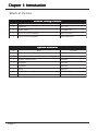
Chapter 1: Introduction
What’s in the box:
A V R ou t e r P a c k a g e C on t e n t s
Ite m
QTY
Pa rt No.
1
AVRoute r
AV * X*
1
Powe r Cord
CCPW R110V
1
RS232 to RS422 Ad a pte r
SM-R232R422
1
RS422 to RJ45 Ad a pte r
SM-RJ45RS422
O pt i on a l A c c e ssor i e s
QTY
Pa rt No.
Ite m
1
Vid e o Ca ble (XVGA) Ma le to Ma le
CC-SVGAMM-06
1
Au d io Ca ble (3.5mm to RCA Le ft a nd Right)
CC-MRAMM-06
1
Re mote Control Unit
SM-RMT
1
IR Bla ste r
SM-16B
1
IR Emitte r
SM-LED
1
IR Eye
SM-EY E
1
SLX-100 Re ce ive r Unit
SLX-RX100
1
SXL-200 Re ce ive r Unit
SLX-RX200
Page 4
AVRouter Manual Version 1.0
Chapter 1: Introduction
Overview
At times multiple AV signals need to be transferred to multiple nearby ouput monitors. The AV
Router allows multiple VGA/audio inputs to be routed to multiple outputs simultaneously, by way
of a direct connection into the router.
The AV Router is a high-quality switching matrix for VGA type signals. All signal formats are catered
for including VGA, SVGA, XGA, RGBHV and sync on green (SOG) applications. For ease of installation,
Standard VGA connectors (HD15 sockets) are used for the input as well as the output video signal.
All that is required is a standard pin-to-pin VGA cable to connect to the signal source.
Stereo audio can also be routed to multiple outputs. The audio can either be routed independently
or together with the video signal using the SmartControl software that is very easy to use.
Note: for maximum signal performance, use only high quality cable that has internal coaxial cable
for each color.
The units contain a very high bandwidth routing matrix for the Red, Green and Blue video channels.
Applications
•
•
•
•
•
•
•
•
•
•
Wall Displays
Audio Visual Presentation
Digital media
Shopping centers
Airports
Security
Dealer rooms
Point of sale
Control rooms
Hotels
AVRouter Manual Version 1.0
Page 5
Chapter 2: Installation
Connecting the AVRouter (Quick Start)
Warning: As a precaution, we recommend that you disconnect all power cords and make sure
that all devices are turned off.
1. Plug in all external audio/video sources to the back of the AVRouter. (Inputs)
2. Connect all external monitors and speakers to the back of the AVRouter. (Outputs)
3. Connect RS232/RS422 adapter to the male serial port on your computer. Then connect
4.
5.
6.
7.
the RS422/RJ45 adapter to that first adapter
Use CAT5 cable to connect the adapters (from computer) to the right (R) CAT5 terminal
on the front panel of the AVRouter unit.
Plug power cable into the AVRouter unit.
Install SmartControl software.
Power on the AVRouter.
Note: 2 adapters will be connected together. This is normal. RS232 to RS422 to RJ45.
Page 6
AVRouter Manual Version 1.0
Chapter 2: Installation
Connecting the AVRouter (Detailed Instructions)
Video and Audio Inputs
The video input for the AVRouter is a standard HD15 connection.
Connect all of the Input video sources to the back of the AVRouter unit. The inputs are
located on the right half of the rear panel.
Hint: You may want to label the input video connections so as not to lose track of where
the signal is coming from. Later on when the software is installed you will be able to give
each connection a name and the software will remember it for you. This way you can
switch the video connections without having to look at the physical connections on the
back of the unit. (You can also use the included page at the end of this manual in order
to keep track of the connections as you make them.)
The audio inputs for the AVRouter are standard 3.5 mm Stereo Miniplug connectors.
Connect all of the audio inputs to the back of the AVRouter unit. The inputs are located
on the right half of the rear panel. Many computer audio sources use this standard
connection but there is other equipment such as receivers, and VCRs where a special
adapter cable will be needed. Such as a 3.5mm miniplug to stereo RCA cable.
Make sure that the audio and video are coming from the same source and are plugged
the same input number. For example, if the audio from one computer is connected to
input 1, then the video should also be connected to input 1.
Video and Audio Outputs
The video and audio connections for the AVRouter outputs are exactly the same. The only difference is that they are located on the left side of the back panel
Connect all of the external video monitors and corresponding speakers to the output
connections located on the back of the AVRouter unit.
AVRouter Manual Version 1.0
Page 7
Chapter 2: Installation
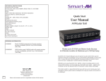
Connecting the Communication Cable: RS422
Each unit can be controlled by a RS422 port connected via a RJ45 on the front of the chassis. Two
connectors are provided for expansion, allowing a simple Cat 5 patch cable to link to additional
units. The SmartControl software will be used to control the units.
There are 2 adapters:
• RS232 to RS422 adapter (Connects to the serial port on your computer)
• RS422 to RJ45 adapter (connects to the other adapter as well as the AVRouter Unit)
1. Connect the RS232 to RS422 adapter into the control computer by connecting the
female RS232 connector into the male RS232 connector of the PC. Turn the side screws
so that it does not accidentally become disconnected
2. Connect the RS422 to RJ45 adapter to the other adapter by connecting the female end
into the male connector of the other adapter.
3. Run a single UTP CAT5 cable from this connector to the front of the AVRouter unit.
4. Connect CAT5 connector to the COMMS connector on the right.
Page 8
AVRouter Manual Version 1.0
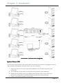
Chapter 2: Installation
AVRouter connection diagram
System Power ON
You are now ready to turn on the system. Make sure that all connections are plugged in and all
video monitors and speakers that you wish to use are connected.
1. Plug in the power cord to the back of the AVRouter unit. Connect this power cord
to the wall.
2. Turn computer on and make sure that the boot up process has completed.
3. Observe to see if LEDs are lit. The AVRouter unit has two. One of those LEDs is for
the power and the other is to indicate that the unit is functioning properly.
4. Power on all external monitors and speakers.
AVRouter Manual Version 1.0
Page 9
Chapter 3: Software Installation & Operation
Find the Installation CD that came with your AVRouter unit. This CD has the SmartControl
software that you will need in order to control the unit using a computer.
Insert the CD into your CD-ROM. On the CD you should see:
SmartControl Installer.exe
SmartControl Help File
AVRouter Manual in PDF format
Double click SmartControl.exe in order to initiate software installation. Click Install. After
installation has completed, click CLOSE.
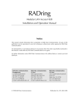
In order to use the software, click on the START button>Programs>SmartControl. There you
should see a help file, the SmartControl launcher as well as a shortcut to uninstall SmartControl.
Click on SmartControl in order to launch the software.
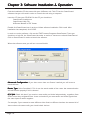
When the software starts you will see a screen like this.
Advanced Configuration: If you have more than one Router installed you will want to
check this box.
Router Type: Select SmartNet-X. This is not the actual model of the router but communication
will still function properly if this is selected.
A/V Split: Check this box if you need to route audio and video independently, regardless from
which source they originated from. Leave unchecked if you want audio and video signals from
the same input to remain together.
For example, if you wanted to route different video feeds to different locations but wanted all of
them to have the same audio, you should check the box.
Page 10
AVRouter Manual Version 1.0
Chapter 3: Software Installation & Operation
Inputs/Outputs: Enter the number of Inputs/Outputs your AVRouter has. For now we will
assume that there are 16 inputs and 16 outputs.
Com Port: Select the appropriate com port that your computer is using to access the router.
Router Timeout: By default this is 0 meaning the computer acknowledges commands almost
instantly. Sometimes a computer takes longer to respond. This setting should be left at 0. If you
need to change it, it should be no higher than 0.2.
After you have entered in the necessary information click OK.
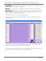
This will now take you to the Main Routing Window where you can route the different video/
audio connections.
On this screen you will notice the input buttons running down the left side while the output
buttons run across the top. They are each labeled 1 through 16.
Note: The three small colored buttons at the lower right labeled ALL, VIDEO, and AUDIO are not
available if AV Split was not checked when you configured your router.
AVRouter Manual Version 1.0
Page 11
Chapter 3: Software Installation & Operation
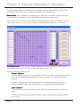
The Main Routing Window enables you to control the router(s) connections by means of the
matrix panel, the button panel, or with pre-recorded routes called macros.
Matrix Panel: This is probably the simplest way to route the connections. Simply click on the
cross point itself. The input on the left will then be routed to the output above.
Note: Inputs can be routed to several different outputs, but each output can only have a single
input at any one time. So you can have several connections horizontally but not vertically.
The Button Panel: These are the numbered buttons across the top and left sides. Click an
output button on the top, and then click an input button on the left.
Options for using the Button Panel
Output Options:
To select multiple outputs next to each other, click on one output, then hold the shift key
down and click the last output. When the input is clicked, it is routed to all selected
outputs
To select multiple outputs individually, hold the control key down and click on any
number of outputs. When the input is clicked, it is routed to all selected outputs.
Input Options:
To route an input to all the outputs at once, hold the control key down and click on an
input.
To leave the outputs selected after the route is made, hold the shift key down and click
on an input.
Page 12
AVRouter Manual Version 1.0
Chapter 3: Software Installation & Operation
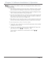
Macros: This section of the window is used to save and play back macros. Macros store a
set sequence of routes.
To record a macro:
1. . Click on the Record button (last button shown above). A blinking “recording” message
below this button will be displayed to indicate that all routes are being recorded.
2. . Select the desired cross points. (See Matrix Routing for details on making these routes.)
There is no limit on the number of routes you may record.
3. If you click a macro button while in the record mode, the macro will be executed, and
these routes will be added to the recording. This makes it possible to combine the
routes of two or more macros into one bigger macro.
4. When finished, click the “Save Macro” button. You will be instructed to then click on
one of the macro buttons. Doing this will save the recorded routes to that button.
To cancel saving the macro, click the “Cancel Save” button.
5. To play back a macro, simply click on one of the 50 macro buttons. Use the scrollbar
to bring any of these into view.
6. The macros are automatically saved in the current configuration file. They are also
saved when you select the File/Save Configuration... menu.
To save macros in a separate file for a special purpose, select the File/Save
Macros...menu.
AVRouter Manual Version 1.0
Page 13
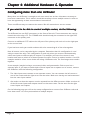
Chapter 4: Additional Hardware & Operation
Configuring more than one AVRouter
Many times one AVRouter is enough to suit ones needs, but at times it becomes necessary to
have more connections. This is when it would be necessary to have multiple routers in order to
have the opportunity to have more advanced connections.
There are different ways to connect the routers. We will assume there are two routers.
If you want to be able to control multiple routers, do the following:
The AVRouter has two RJ45 connectors on the front of the unit. These connectors are used to
control the units using a PC. The COMMS cable should already be connected to the right RJ45
connector on the primary unit.
Connect an additional CAT5 cable to the left port of the primary unit and run it to the right port
on the second unit.
If you had more units you would continue this series connecting all of the units together.
Now all routers can be controlled by the computer. Remember that this configuration is used
solely to control the units. This configuration is used only when you want to simulataneously
switch two inputs to different pairs of outputs.. For example: you have four screens in one
location and want to switch all of those inputsto four other screens in another location. A real life
example would be a four screen video wall using 4 AVRouter units. The four images must remain
together.
As an example. Imagine having a two-screend video wall presentation. Each screen has a
seperate input. If you want to switch both of these inputs into a separate set of screens, connect
the AVRouters with the following configuration:
1
The video inputs must connect to two seperate routers. You can connect the left screen to
one of the routers and the right screen into the other. Make sure that thy are both connected
into the same input number.
2
Also make sure that the outputs are also seprated into the different routers. Make sure that all
of the left screen inputs and outputs remain on the same router. Do the same for the right
screen inputs and outputs.
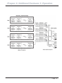
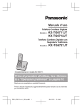
On the following page you will see the setup configuration to connect four AVRouter units and
have them route a 4 screen presentation to multiple outputs.
Page 14
AVRouter Manual Version 1.0
Chapter 4: Additional Hardware & Operation
AVRouter Manual Version 1.0
Page 15
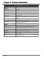
Chapter 5: Technical Information
M ATR I X S P E C I F I C ATI O N S
ITEM
Video
Ba nd wid th
Inpu t Signa l Le ve l
Ou tpu t Impe d a nc e
200MHz
1Volt pk-pk into 75R
100 Ohms
Inpu t Impe d a nc e
75R Ohms
Conne c tor
F orma t
HD15 soc ke t
VGA/SVGA/XGA/RGBHV/RGsB/CVBS/Y C/Y UV/RGBS
TTL5VDC
Horizonta l Sync u p to 85KHz
640x480, 600x800, 1024x768,
280x1024,1600x1200
S yn c s
Ba nd wid th
Re solu tion
Au d i o
Signa l
Conne c tor
F re qu e nc y Re sponse
P owe r
Volta ge
P h y si c a l
W e i ght
Dime nsion (HxW xD)
Page 16
DESCRIPTION
15KHz 0d B u nba la nc e d 10000ohms impe d a nc e
3.5mm Ste re o Ja c k (Inpu t a nd Ou tpu t)
20 Hz to 20 kHz, +/-0.5 d B
90-230V IEC 1A A/S 50/60 Hz
4kg (8.8lbs)
133x441x287mm (5.2x17
is 482mm or 19in.
AVRouter Manual Version 1.0
x11.3) *F ront of u nit
3/8
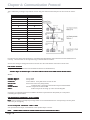
Chapter 6: Appendices
Although the following communication protocol has been specifically written for the SmartNet-X unit from SmartAVI, it
is accurate for the AVRouter and other units from SmartAVI.
1.0 Document Conventions
Any numbers preceded by ‘0x’ are hexadecimal.
All data byte string listed in examples are in hexadecimal.
(base 16)
(base 16)
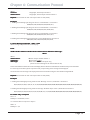
2.0 Comms Ports Settings.
The Host Controller Serial Port should be configured as detailed in the table below
B a u d Ra te
S ta r t B i ts
D a ta B i ts
P a r i ty
S t op B i t s
3.0
RS232/422
9600
1
8
N on e
1
converter.
The Frame control interface uses RS422. A full duplex 5 wire balanced communications standard that allows
communications to be multi-dropped to more than one Frame.
Since PC’s only come with RS232 ports a small converter is required to convert the RS232
signals to RS422.
If you purchased any of the SmartControl software options you will have received a suitable converter and cable.
In the event that you wish to purchase your own converter and/or make your own comms cable please see Appendix
A at the rear of this document for more information.
4.0
Conne
cti
ng
Connecti
cting
up
4.1. Plug the RS232 end of the RS232 to RS422 converter directly onto the selected comms port on the rear of your
computer.
4.2. Plug the comms cable (D9 end) onto the end of the RS422 end of the RS232/RS422
converter.
4.3. Plug the RJ45 end of the comms cable into the IN port on the front of the SmartNet-X or SmartNet-V.
5.0
SmartN
e tX
SmartNe
t-X
Frame
Switches
The communications port on the SmartNet-X allows for multiple chassis to be connected together.
AVRouter Manual Version 1.0
Page 17
Chapter 6: Communication Protocol
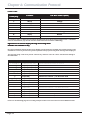
This is achieved by creating a loop between chassis using the comms IN and OUT ports on the front of the chassis.
i.e.
A d d r e ss
0
1
2
3
4
5
6
7
8
9
10
10
11
11
12
12
13
13
14
14
15
15
H e x S wi t c h S e t t i n g
0
1
2
3
4
5
6
7
8
9
A
B
C
D
E
F
In order to ensure good communications it is essential that the Hex address switch on the front of the SmartNet-X is set
correctly. The hex switch can be adjusted using a small flat blade screwdriver.
An incorrect setting or having more than one chassis set to the same address will result in comms errors.
6.0 Packet Structure
The general form of packets sent to the SmartNet-X switches are detailed below;
<Header Byte 0><Header Byte 1><Frame Address><Reserved><CMD><DATA BYTES><BCC>
Where ;
<Header Byte 0>
<Header Byte 1>
<Address>
<Reserved>
<CMD>
<DATA BYTES>
<BCC>
Always 0xBE
Always 0xEF
Frame address. Set by Hex switch on front of unit.
Reserved for future use (Always 0x00)
Command byte – Determines the number of bytes in DATA BYTES
Number of bytes for associated CMD
XOR of all bytes in the string up to but not including BCC
On receipt of a valid data packet the SmartNet-X will either respond with an ACK (0x06) or a valid packet
containing the requested data.
7.0 Implemented Commands @ 18/11/2003
Note: Commas shown in example byte strings below are not transmitted from the serial port they have only been
added only to aid legibility.
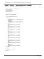
7.1 Set Crosspoint Command : CMD = 0x00
Sets specified switch output or Destination to the specified input or Source.
Send:
<0xBE><0xEF><Address><0x00><0x00><Source><Destination><BCC>
Page 18
AVRouter Manual Version 1.0
Chapter 6: Communication Protocol
Where;
<Source>
<Destination>
=Single Byte, Switch Input channel -1
=Single Byte, Switch output channel number -1
Response: If successful the unit will respond with an ACK (0x06)
Examples
1. Sending the following byte string sets Source 1 to Destination 1 on chassis 0
0xBE,0xEF,0x00,0x00,0x00,0x00,0x00,0x51,
2. Sending the following byte string sets Source 2 to Destination 1 on chassis 0
0xBE,0xEF,0x00,0x00,0x00,0x01,0x00,0x50,
3. Sending the following byte string sets Source 2 to Destination 2 on chassis 0
0xBE,0xEF,0x00,0x00,0x00,0x01,0x01,0x51,
4. Sending the following byte string sets Source 16 to Destination 16 on Frame 15
0xBE,0xEF,0x0F,0x00,0x00,0x0F,0x0F,0x5E,
7.2 Send Message Command : CMD = 0x01
Writes message to specified On Screen Display.
Send:
<0xBE><0xEF><Address><0x00><0x01><Destination><OSDLine><Message>
<BCC>
Where;
<Destination>
<OSDLine>
<Message>
=Switch output channel number –1
= Screen Line number
= This section MUST be 28 bytes long
(Please see the following text for more details on this )
Due to the limitations of both the On Screen Display and the amount of available non-volatile memory in the SmartNet
it is necessary for the Host system to perform some pre-processing of the message to be displayed.
The characters in the message to be displayed need to be translated using the rules detailed in Appendix B.
Response: If successful the unit will respond with an ACK (0x06)
Examples
1. Sending the following byte string sends the text “Message” to Line 2, destination 1 of Switch 0
BE,EF,00,00,01,00,02,18,2E,3C,3C,2A,30,2E,0B,0B,0B,0B,0B,0B,0B,0B,0B,0B,0B,0B,0B,0B,0B,0B,0B,0B,0B,0B,0B,5B,
2. Sending the following byte string sends the message “Abandon Ship!” to line 6, destination 6 of switch 5
BE,EF,04,00,01,05,06,0C,2B,2A,37,2D,38,37,0B,1E,31,32,39,0B,0B,0B,0B,0B,0B,0B,0B,0B,0B,0B,0B,0B,0B,0B,0B,60,
Set Video Only Crosspoint
Cmd = 3
Databytes = destination, source
i.e. to switch video on output 3 to input 4
CMD = 3
Databytes = 3,4
AVRouter Manual Version 1.0
Page 19
Chapter 6: Communication Protocol
Set Audio Only Crosspoint
Cmd = 4
Databytes = destination, source
i.e. to switch audio on output 3 to input 4
CMD = 3
Databytes = 3,4
Mute Video on specified output
Cmd = 5
Databytes = Destination, State (0=off, 1 = on)
i.e. to turn video off on output 3
CMD=5
Databytes = 3,0
i.e. to turn video on on output 3
Mute Audio on specified output
Cmd = 6
Databytes = Destination, State (0=off, 1 = on)
i.e. to turn audio off on output 3
CMD=6
Databytes = 3,0
i.e. to turn video on on output 3
CMD=6
Databytes = 3,1
Split Crosspoints - Video and Audio Differently
Cmd = 7
Not specified yet but will exist
Get Current Status
CMD 8 = current Status all
Databytes = Destination. (1-16 = specific output, 0xff = all)
i.e. to read the status of output 3 send;
CMD = 8
Databyte = 3
i.e. to read the status of all outputs
CMD=8
Databytes = 0xff
Unit will return Valid PSU as above where databytes is;
a single byte indicating currently selected source if specific destination was requested
or a string of 16 bytes indicating currently selected source for each destination starting with destination 1.
Page 20
AVRouter Manual Version 1.0
Chapter 6: Communication Protocol
The command to make the end of CAT5 line receiver (SLRX-RX300) switch between its local and remote sources
is as follows;
<0xBE><0xEF><Frame Address><Reserved><CMD><DATA BYTES><BCC>
Where;
<0xBE> always 0xBE
<0xEF> always 0xEF
<Frame Address> Frame address. Set by Hex switch on unit or position in Rack frame.
<RESERVED> always 0x00
<CMD> 50 (0x32)
<DATABYTES> is Two bytes <DESTINATION><SOURCE> 0L = Receiver LOCAL Video/Audio, 1 =
Receiver REMOTE Video/Audio
<BCC>
So if switching the Receiver on output 3 of Frame 2 to its local source send
<0xBE><0xEF><0x02><0x00><0x32><0x02><x00><0x63>
Get System Information
Cmd = 0xff
Databytes = NULL (none)
Unit will return a valid PSU as detailed above where Databytes are as follows
<product type>, <switch configuration> , <version>
Where Product Type =
1 Byte;
0 = SmartNet V
1 = SmartNet X
3 = SLX-TX550
4 = SLX-RX300
Where Switch configuration =
2 Bytes;
<inputs><outputs>
Where Version =
3 bytes
<Version><issue><release>
Appendix A: RS232/422 Converter and Comms Cable
RS232/RS422 Converter
A suitable RS232/RS422 product can be purchased from KK Systems in Brighton, East
AVRouter Manual Version 1.0
Page 21
Chapter 6: Communication Protocol
Comms Cable
D B 9 c a bl e
e n d e d pl u g
1
2
3
4
5
6
7
8
9
F u n c t i on
U TP W i r e C ol ou r s ( R J 4 5 )
RX - ( A)
T X+ (B)
0V
0V
0V
0V
RX+ ( B)
T X - ( A)
-
Or a n g e
W h i te & B r o w n
Blue
G reen
W h i te & Or a n g e
Brown
-
You will also require a cable that sits between the RS422 port of the K2 converter and the Frame. It should be
wired as shown below. (Tip: Cut the end off a CAT5 Patch lead and attach a DB9 Plug)
Appendix B: On Screen Display Message Processing Rules.
Available on SmartNet-V only
Due to the limitations of both the On Screen Display and the amount of available non-volatile memory in the
SmartNet it is necessary for the Host system to perform some pre-processing of the message to be displayed.
The message string needs to be parsed character by character and the values translated according to
the table below.
Ch a r a c te r s
" 0 " T hr o ugh " 9 "
Tr a n sl a t i on R u l e
C hr $ ( As c( s C ha r ) - 4 8 )
C om m e n t
S u b tr a ct 4 8 f r o m AS C II v a l u e o f ch a r a cte r
" A" T hr o ugh " Z "
C hr $ ( As c( s C ha r ) - 5 3 )
S u b tr a ct 5 3 f r o m AS C II v a l u e o f ch a r a cte r
" a " T hr o ugh " z "
C hr $ ( As c( s C ha r ) - 5 5 )
S u b tr a ct 5 5 f r o m AS C II v a l u e o f ch a r a cte r
"."
C h r $ ( &H 2 7 )
S u b s ti tu te th e ch a r a cte r " . " f o r AS C II v a l u e 0 x 2 7
" " ( s p a ce )
C h r $ ( &H 0 b )
S u b s ti tu te th e ch a r a cte r " " f o r AS C II v a l u e 0 x 0 b
":"
C h r $ ( &H 2 6 )
S u b s ti tu te th e ch a r a cte r " : " f o r AS C II v a l u e 0 x 2 6
" /"
C h r $ ( &H 2 8 )
S u b s ti tu te th e ch a r a cte r " /" f o r AS C II v a l u e 0 x 2 8
" " " ( Ap o s tr o p h e )
C h r $ ( &H 2 9 )
S u b s ti tu te th e ch a r a cte r " " " f o r AS C II v a l u e 0 x 2 9
"-"
C h r $ ( &H 0 A )
S u b s ti tu te th e ch a r a cte r " - " f o r AS C II v a l u e 0 x 0 a
"?"
C h r $ ( &H 7 0 )
S u b s ti tu te th e ch a r a cte r " ? " f o r AS C II v a l u e 0 x 7 0
"*"
C h r $ ( &H 5 F )
S u b s ti tu te th e ch a r a cte r " * " f o r AS C II v a l u e 0 x 5 f
"="
C h r $ ( &H 7 8 )
S u b s ti tu te th e ch a r a cte r " = " f o r AS C II v a l u e 0 x 7 8
">"
C h r $ ( &H 7 A )
S u b s ti tu te th e ch a r a cte r " > " f o r AS C II v a l u e 0 x 7 8
"<"
C h r $ ( &H 7 B )
S u b s ti tu te th e ch a r a cte r " < " f o r AS C II v a l u e 0 x 7 b
"("
C h r $ ( &H 6 1 )
S u b s ti tu te th e ch a r a cte r " ( " f o r AS C II v a l u e 0 x 6 1
")"
C h r $ ( &H 6 2 )
S u b s ti tu te th e ch a r a cte r " ) " f o r AS C II v a l u e 0 x 6 2
Please see the following page for a working example of these rules in the form of a Visual BASIC function.
Page 22
AVRouter Manual Version 1.0
Chapter 6: Communication Protocol
Appendix B: Continued…..
(Sample Translation routine in Visual BASIC)
Function LookUpOSDString(sTextMessage As String) As String
‘
‘ Look up chars and translate to message for OSD
‘
Dim iLoop As Integer
Dim sNewMess As String
Dim sChar As String
sNewMess = Space$(MAX_SCREEN_CHAR)
For iLoop = 1 To Len(sTextMessage)
sChar = Mid$(sTextMessage, iLoop, 1)
Select Case sChar
Case “0” To “9”
Mid$(sNewMess, iLoop, 1) = Chr$(Asc(sChar) - 48)
Case “A” To “Z”
Mid$(sNewMess, iLoop, 1) = Chr$(Asc(sChar) - 53)
Case “a” To “z”
Mid$(sNewMess, iLoop, 1) = Chr$(Asc(sChar) - 55)
Case “.”
Mid$(sNewMess, iLoop, 1) = Chr$(&H27)
Case “ “
Mid$(sNewMess, iLoop, 1) = Chr$(&HB)
Case “:”
Mid$(sNewMess, iLoop, 1) = Chr$(&H26)
Case “/”
Mid$(sNewMess, iLoop, 1) = Chr$(&H28)
Case “‘“
Mid$(sNewMess, iLoop, 1) = Chr$(&H29)
Case “-”
Mid$(sNewMess, iLoop, 1) = Chr$(&HA)
Case “?”
Mid$(sNewMess, iLoop, 1) = Chr$(&H70)
Case “*”
Mid$(sNewMess, iLoop, 1) = Chr$(&H5F)
Case “=”
Mid$(sNewMess, iLoop, 1) = Chr$(&H78)
Case “>”
Mid$(sNewMess, iLoop, 1) = Chr$(&H7A)
Case “<“
Mid$(sNewMess, iLoop, 1) = Chr$(&H7B)
Case “(“
Mid$(sNewMess, iLoop, 1) = Chr$(&H61)
Case “)”
Mid$(sNewMess, iLoop, 1) = Chr$(&H62)
Case Else
Mid$(sNewMess, iLoop, 1) = Chr$(&HB)
End Select
Next iLoop
LookUpOSDString = sNewMess
End Function
AVRouter Manual Version 1.0
Page 23
Chapter 6: Appendices
Limited Warranty Statement
A.
1.
2.
3.
4.
5.
6.
Extent of limited warranty
SmartAVI Technologies, Inc. warrants to the end-user customers that the SmartAVI product
specified above will be free from defects in materials and workmanship for the duration of 1
year, which duration begins on the date of purchase by the customer. Customer is responsible
for maintaining proof of date of purchase.
SmartAVI limited warranty covers only those defects which arise as a result of normal use of
the product, and do not apply to any:
a. Improper or inadequate maintenance or modifications
b. Operations outside product specifications
c. Mechanical abuse and exposure to severe conditions
If SmartAVI receives, during applicable warranty period, a notice of defect, SmartAVI will at
its discretion replace or repair defective product . If SmartAVI is unable to replace or repair
defective product covered by the SmartAVI warranty within reasonable period of time,
SmartAVI shall refund the cost of the product.
SmartAVI shall have no obligation to repair, replace or refund unit until customer returns
defective product to SmartAVI.
Any replacement product could be new or like new, provided that it has functionality at
least equal to that of the product being replaced.
SmartAVI limited warranty is valid in any country where the covered product is distributed
by SmartAVI.
B. Limitations of warranty
TO THE EXTENT ALLOWED BY LOCAL LAW , NEITHER SMARTAVI NOR ITS THIRD PARTY SUPPLIERS
MAKE ANY OTHER WARRANTY OR CONDITION OF ANY KIND WHETHER EXPRESSED OR IMPLIED
, WITH RESPECT TO THE SMARTAVI PRODUCT , AND SPECIFICALLY DISCLAIM IMPLIED WARRANTIES
OR CONDITIONS OF MERCHANTABILITY, SATISFACTORY QUALITY , AND FITNESS FOR A PARTICULAR
PURPOSE
C. Limitations of liability
To the extent allowed by local law the remedies provided in this warranty statement are the
customers sole and exclusive remedies
TO THE EXTENT ALLOWED BY LOCAL LAW , EXCEPT FOR THE OBLIGATIONS SPECIFICALLY SET
FORTH IN THIS WARRANTY STATEMENT , IN NO EVENT WILL SMARTAVI OR ITS THIRD PARTY
SUPPLIERS BE LIABLE FOR DIRECT, INDIRECT, SPECIAL, INCIDENTAL, OR CONSEQUENTIAL DAMAGES
WHETHER BASED ON CONTRACT , TORT OR ANY OTHER LEGAL THEORY AND WHETHER ADVISED
OF THE POSSIBILITY OF SUCH DAMAGES.
D. Local law
To the extent that this warranty statement is inconsistent with local law, this warranty statement
shall be considered modified to be consistent with such law.
Page 24
AVRouter Manual Version 1.0
Chapter 6: Appendices
Input
De scription
Output
1
1
2
2
3
3
4
4
5
5
6
6
7
7
8
8
9
9
10
10
11
11
12
12
13
13
14
14
15
15
16
16
17
17
18
18
19
19
20
20
21
21
22
22
23
23
24
24
25
25
26
26
27
27
28
28
29
29
30
30
31
31
32
32
De scription
AVRouter Manual Version 1.0
Page 25
SmartAVI, Inc.
3111 Winona Ave, Suite 101
Burbank, CA 91504
Tel (818) 565-0011 Fax (818) 565-0020
Email: [email protected]