1
Kramer Electronics, Ltd.
USER MANUAL
Model:
VS-3232Vxl
32x32 Video Matrix Switcher
Contents
Contents
1
2
2.1
3
4
4.1
5
6
6.1
6.2
Introduction
Getting Started
Quick Start
Overview
Your Video Matrix Switcher
Using the IR Transmitter
Installing the VS-3232Vxl on a Rack
Connecting the Video Matrix Switcher
Connecting the VS-3232Vxl as a Composite Video Switcher
Assembling a Multi-channel Video Switcher
1
1
1
3
4
9
10
11
11
13
6.2.1
6.2.2
6.2.3
Configuring a 32x32 Y/C Switcher (Two Units)
Configuring a 32x32 YUV/RGB Switcher (Three Units)
Configuring a 32x32 RGBS Switcher (Four Units)
14
15
16
6.3
Dipswitch Settings
16
6.3.1
6.3.2
6.3.3
6.3.4
Setting the MACHINE #
Understanding the System Mode
Understanding the Slave Mode
The System Mode versus the Master/Slave Mode
17
17
18
19
6.4
Connecting a Control Interface
19
6.4.1
6.4.2
Connecting the RS-232 Control Interface
Connecting the RS-485 Control Interface
20
22
6.5
6.6
Configuring the Sync
Controlling via the ETHERNET
25
26
6.6.1
6.6.2
6.6.3
Connecting the ETHERNET Port directly to a PC (Crossover Cable)
Connecting the ETHERNET Port via a Network Hub (Straight-Through Cable)
Control Configuration via the Ethernet Port
26
27
27
7
7.1
Operating Your Video Matrix Switcher
Startup Display
28
28
7.1.1
Viewing the Display
29
7.2
7.3
Using the Selector Buttons
Confirming Actions
29
29
7.3.1
7.3.2
Toggling between the At Once and Confirm Modes
Confirming a Switching Action
30
30
7.4
Switching Options
30
7.4.1
7.4.2
7.4.3
7.4.4
7.4.5
7.4.6
Switching one Input to one Output
Switching several Inputs to several Outputs
Switching one Input to all Outputs
Clearing an Output
Clearing several Outputs
Clearing all Outputs
31
31
32
32
32
32
7.5
Storing and Recalling Setups
33
i
Contents
7.5.1
7.5.2
Storing Setups
Recalling Setups
33
33
7.6
7.7
7.8
8
8.1
8.2
8.3
8.4
8.5
8.6
8.7
8.8
9
9.1
Using the DEFAULT SETUP Button (Unity Setting)
Choosing the FOLLOW or the BREAKAWAY Modes
Using the LOCK Button
The MENU Commands
Selecting the SYNC Configuration
Selecting the INTERFACE Configuration
Selecting the Interface REPLY Configuration
Selecting the PROTOCOL Configuration
Selecting the DEFAULT Setup Configuration
Selecting the store DEFAULT Setup Configuration
The Main Firmware Version
Selecting the TOTAL RESET Option
Flash Memory Upgrade
Switcher Flash Memory Upgrade
34
35
36
37
39
39
40
40
40
40
41
41
42
42
9.1.1
9.1.2
9.1.3
Downloading from the Internet
Connecting the PC to the RS-232 Port
Upgrading Firmware
42
42
43
9.2
Ethernet Flash Memory Upgrade
47
9.2.1
9.2.2
9.2.3
Downloading from the Internet
Connecting the PC to the RS-232 Port
Upgrading Firmware
47
47
48
10
11
11.1
11.2
Technical Specifications
Communication Protocols
The Kramer 2000 Communication Protocol
ASCII Protocol: General
49
50
50
55
11.2.1 ASCII Protocol: Description
55
Figures
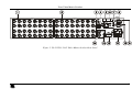
Figure 1: VS-3232Vxl 32x32 Video Matrix Switcher Front Panel
5
Figure 2: VS-3232Vxl 32x32 Video Matrix Switcher Rear Panel
7
Figure 3: Configuring the VS-3232Vxl for Composite Video
12
Figure 4: Configuring a 32x32 s-Video (YC) Switcher with two VS-3232Vxl Switchers 14
Figure 5: Configuring a 32x32 YUV (RGB) Switcher with three VS-3232Vxl Switchers 15
Figure 6: Dipswitches
16
Figure 7: Connecting a PC to Three VS-3232Vxl Units
20
Figure 8: RS-485 Connector PINOUT
22
Figure 9: Connecting the RS-485 Connectors between two VS-3232Vxl Units
23
Figure 10: RS-485 Control Interface and SYNC Connections for Component Switcher 24
Figure 11: Local Area Connection Properties Window
26
Figure 12: Internet Protocol (TCP/IP) Properties Window
27
Figure 13: Default Startup Status Display Sequence
28
Figure 14: Setting the SYNC Configuration (an example)
38
ii
KRAMER: SIMPLE CREATIVE TECHNOLOGY
Contents
Figure 15: Splash Screen
Figure 16: Atmel – Flip Window
Figure 17: Device Selection Window
Figure 18: Device Selection window
Figure 19: Loading the Hex
Figure 20: RS-232 Window
Figure 21: Atmel – Flip Window (Connected)
Figure 22: Atmel – Flip Window (Operation Completed)
Figure 23: The KFR-Programmer Window
43
43
44
44
45
45
46
46
48
Tables
Table 1: Front Panel VS-3232Vxl 32x32 Video Matrix Switcher Features
Table 2: Rear Panel VS-3232Vxl 32x32 Video Matrix Switcher Features
Table 3: Dipswitch Definitions
Table 4: Machine # Dipswitch Settings
Table 5: The System Mode versus the Slave Mode
Table 6: SYNC Configuration Menu
Table 7: INTERFACE Configuration Menu
Table 8: Interface REPLY Configuration Menu
Table 9: PROTOCOL Configuration Menu
Table 10: DEFAULT Setup Configuration Menu
Table 11: Total Reset Menu
Table 12: Technical Specifications of the VS-3232Vxl Video Matrix Switcher
Table 13: Hex Table (IN 1-32 to OUT 1-16)
Table 14: Hex Table (IN 1-32 to OUT 17-32)
6
8
16
17
19
39
39
40
40
40
41
49
51
53
iii
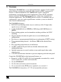
Introduction
1
Introduction
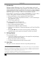
Welcome to Kramer Electronics (since 1981): a world of unique, creative and
affordable solutions to the infinite range of problems that confront the video, audio
and presentation professional on a daily basis. In recent years, we have redesigned
and upgraded most of our line, making the best even better! Our 500-plus different
models now appear in 8 Groups1, which are clearly defined by function.
Congratulations on purchasing your Kramer VS-3232Vxl 32x32 Video Matrix
Switcher. This product is ideal for the following typical applications:
Professional display systems requiring video signal routing
Broadcast, presentation and production facilities, as well as monitoring in
large duplication systems
Rental/staging applications
The package includes the following items:
VS-3232Vxl 32x32 Video Matrix Switcher
Power cord and null-modem adapter
Windows®-based Kramer control software2
Windows®-based Ethernet Configuration Manager and Virtual Serial Port
Manager
Kramer RC-IR2 Infra-red remote control transmitter (including the
required batteries and a separate user manual3) and this user manual3
2
Getting Started
We recommend that you:
Unpack the equipment carefully and save the original box and packaging
materials for possible future shipment
Review the contents of this user manual
Use Kramer high performance high resolution cables4
2.1 Quick Start
This quick start chart summarizes the basic setup and operation steps.
1 GROUP 1: Distribution Amplifiers; GROUP 2: Video and Audio Switchers, Matrix Switchers and Controllers; GROUP 3:
Video, Audio, VGA/XGA Processors; GROUP 4: Interfaces and Sync Processors; GROUP 5: Twisted Pair Interfaces;
GROUP 6: Accessories and Rack Adapters; GROUP 7: Scan Converters and Scalers; and GROUP 8: Cables and Connectors
2 Downloadable from our Web site at http://www.kramerelectronics.com
3 Download up-to-date Kramer user manuals from our Web site: http://www.kramerelectronics.com
4 The complete list of Kramer cables is on our Web site at http://www.kramerelectronics.com
1
Getting Started
2
KRAMER: SIMPLE CREATIVE TECHNOLOGY
Overview
3
Overview
The Kramer VS-3232Vxl is a very high performance, superior x32 vertical
interval matrix switcher for composite video signals on BNC connectors. It
features a video bandwidth of over 500MHz that ensures transparent
performance even in the most critical applications. Three SYNC switching
options make the VS-3232Vxl appropriate for a wide range of glitch-free
transition applications. The VS-3232Vxl can be used as a standalone unit, or
configured as a part of a multi-signal Kramer switcher system, in which all
units switch simultaneously.
The VS-3232Vxl features:
Full 32x32 non-blocking matrix array to switch any of the 32 input video
signals to any or all outputs
A video bandwidth of over 500MHz at 3dB along with 0.1dB flatness to
50MHz
Four switching options, one for immediate switching and three for SYNC
switching
59 preset memory locations for quick access to user-defined special
configurations
Fast access to a preprogrammed default preset configuration (UNITY setting)
Two communication protocols – the Kramer 2000 and the limited Sierra
ASCII
Easy upgrading of the firmware via the Internet
An 80x2 symbol LCD panel with user-friendly information and a
configuration menu
Optional connection to several switchers in one multi-signal video-audio
control system
A LOCK button/remote function to prevent tampering with the front panel
Control the VS-3232Vxl via the front panel buttons, or:
Remotely, by RS-232 or RS-485 serial commands transmitted by a touch
screen system, PC, or other serial controller
Via the ETHERNET
Via the infra-red remote control transmitter
Via an external remote IR Receiver (optional), see section 4.1
The VS-3232Vxl is housed in a 19" 2U rack mountable enclosure.
3
Your Video Matrix Switcher
To achieve the best performance:
Connect only good quality connection cables, thus avoiding interference,
deterioration in signal quality due to poor matching, and elevated noise
levels (often associated with low quality cables)
Avoid interference from neighboring electrical appliances that may
adversely influence signal quality and position your Kramer VS-3232Vxl
in a location free from moisture and away from excessive sunlight and
dust
4
Your Video Matrix Switcher
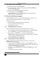
Figure 1 and Figure 2 illustrate the front and rear panels of the VS-3232Vxl,
respectively. Table 1 and Table 2 define the front and rear panels of the
VS-3232Vxl, respectively.
4
KRAMER: SIMPLE CREATIVE TECHNOLOGY
Your Video Matrix Switcher
1
2
3
4
5
6
7
8
9
0
1
2
3
4
5
6
7
8
9
0
TAKE
MENU
LOCK
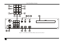
Figure 1: VS-3232Vxl 32x32 Video Matrix Switcher Front Panel
5
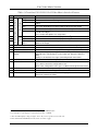
Your Video Matrix Switcher
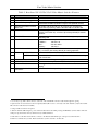
Table 1: Front Panel VS-3232Vxl 32x32 Video Matrix Switcher Features
7
8
9
Feature
ESC
1
STO
1
ALL
Button
Labels
Double-function Selector Buttons Area
4
5
6
Menu Buttons
#
1
2
3
1
OFF
RCL1
ENT
(Forward)
(Backward)
Digits from
0 to 9
10
11
12
13
FOLLOW Button
BREAKAWAY Button
DEFAULT SETUP Button
INPUTS/OUTPUTS LCD
Display
14
15
LOCK Button
MENU Button
16
17
18
TAKE Button
Power Switch
IR Receiver
Function
Press to exit the current operation
Press to store the current setting in the non-volatile memory
Press ALL followed by an input number to connect that input to all the
outputs
Press OFF followed by an output number to disconnect that output
Press to recall a setup from the non-volatile memory
Press to complete the input-output setup when using a one-digit number
2
instead of two digits .
Press to enter the options in a setup menu
3
Press to shift the content of the display to the left
3
Press to shift the content of the display to the right
Select the output to which the input is switched and select the input to
switch to the output
Press to enter the Follow mode in the multi-switcher configuration
Press to enter the Stand-Alone mode in the multi-switcher configuration
Press to recall the default setup (UNITY setting), see section 8.5
Displays the outputs (in the upper row, below the OUTPUTS label)
switched to the selected inputs (in the lower row, above the INPUTS
label).
Displays user interface messages and configuration menu items
Toggle4 to lock/unlock the front panel buttons
Press once to enable the ALL, OFF STO and RCL buttons
Press twice to enter the configuration menu
When in the configuration menu, press to browse through the menu items
Used to confirm and complete setup and switching
Illuminated switch for turning the unit ON or OFF
The red LED is illuminated when receiving signals from the Kramer Infrared remote control transmitter
1 This button is enabled and illuminated after pressing the MENU button
2 For example, to enter input 5, you can either press 0, 5 or 5, ENT
3 Since the LCD display is large enough to show only 13 cross-points out of a total of 32
4 Press and hold the LOCK button for about two seconds to toggle
6
KRAMER: SIMPLE CREATIVE TECHNOLOGY
Your Video Matrix Switcher
Figure 2: VS-3232Vxl 32x32 Video Matrix Switcher Rear Panel
7
Your Video Matrix Switcher
Table 2: Rear Panel VS-3232Vxl 32x32 Video Matrix Switcher Features
#
1
2
3
4
Feature
INPUT BNC Connectors
OUTPUT BNC Connectors
1
REMOTE IR Opening
5
RS-485 Detachable Terminal
Block Port
FLASH MAIN Button
6
ETHERNET Connector
7
FACTORY RESET Button
8
FLASH – Normal Switch
9
10
RS-232
11
12
13
Power Connector with Fuse
SETUP Dipswitches
14
GENLOCK Double BNC
Connectors
TERM 75
IN DB 9F Port
OUT DB 9M Port
Button
Function
Connect to the video sources (from 1 to 32)
Connect to the video acceptors (from 1 to 32)
2
Connects to an external IR receiver unit for controlling the machine via
an IR remote controller (instead of using the front panel IR receiver)
The SYNC and the G PINs are for vertical sync and ground
connection respectively, and the B and A PINs are for RS-485
3
Push in to upgrade the switcher microcontroller to the latest Kramer
firmware (see section 9.1), or release (the factory default) for normal
operation
Connects to the PC or other Serial Controller through computer
networking LAN
Press to reset to factory default definitions4:
IP Address:
192.168.1.39
Mask:
255.255.255.0
Gateway:
192.168.1.1
3
Push in to upgrade the ETH FLASH firmware version (see section
9.2), or release (the factory default) for normal operation
Connects to the PC or the Remote Controller5
Connects to the RS-232 IN DB 9F port of the next unit in the daisychain connection
AC connector enabling power supply to the unit
Dipswitches for setup of the unit (see section 6.2.3)
Press to terminate the GENLOCK SYNC with 75
6
looping
For GENLOCK SYNC input/loop
or release for
1 Covered by a cap. The 3.5mm connector at the end of the internal IR connection cable fits through this opening
2 Optional. Can be used instead of the front panel (built-in) IR receiver to remotely control the machine (only if the internal
IR connection cable has been installed)
3 Using a small screwdriver if required
4 Turn the machine OFF using the power switch and then turn it ON while pressing the ETH Factory Reset button. The unit
will power up and load its memory with the factory default definitions
5 If the unit is not the first unit in the line, connects to the RS-232 OUT DB 9F port of the previous unit in the line
6 Push in to terminate the sync line. Push out when the sync line extends to another unit
8
KRAMER: SIMPLE CREATIVE TECHNOLOGY
Your Video Matrix Switcher
4.1 Using the IR Transmitter
You can use the RC-IR2 IR transmitter to control the machine via the built-in
IR receiver on the front panel or, instead, via an optional external IR receiver1.
The external IR receiver can be located up to 15 meters away from the
machine. This distance can be extended to up to 60 meters when used with
three extension cables2.
Before using the external IR receiver, be sure to arrange for your Kramer
dealer to insert the internal IR connection cable3 with the 3.5mm connector
that fits into the REMOTE IR opening on the rear panel.
Connect the external IR receiver to the REMOTE IR 3.5mm connector.
1 Model: C-A35M/IRR-50
2 Model: C-A35M/A35F-50
3 P/N: 505-70434010-S
9
-3232nd
5
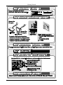
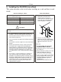
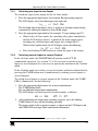
Installing the VS-3232Vxl on a Rack
This section describes what to do before installing on a rack and how to rack
mount.
Before Installing on a Rack
Before installing on a rack, be sure that the environment is
within the recommended range:
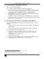
How to Rack Mount
To rack-mount a machine:
1
Attach both ear brackets to the
machine. To do so, remove the
screws from each side of the machine
(5 on each side), and replace those
screws through the ear brackets.
2
Place the ears of the machine
against the rack rails, and insert the
proper screws (not provided) through
each of the four holes in the rack
ears.
Operating temperature range +5 to +45 Deg. Centigrade
Operating humidity range
5 to 65% RHL, non-condensing
Storage temperature range
-20 to +70 Deg. Centigrade
Storage humidity range
5 to 95% RHL, non-condensing
CAUTION!!
When installing on a 19" rack, avoid hazards by taking
care that:
1 It is located within the recommended environmental
conditions, as the operating ambient temperature of a
closed or multi unit rack assembly may exceed the
room ambient temperature.
2 Once rack mounted, enough air will still flow around the
machine.
3 The machine is placed straight in the correct horizontal
position.
4 You do not overload the circuit(s). When connecting
the machine to the supply circuit, overloading the
circuits might have a detrimental effect on overcurrent
protection and supply wiring. Refer to the appropriate
nameplate ratings for information. For example, for
fuse replacement, see the value printed on the product
label.
5 The machine is earthed (grounded) in a reliable way
and is connected only to an electricity socket with
grounding. Pay particular attention to situations where
electricity is supplied indirectly (when the power cord is
not plugged directly into the socket in the wall), for
example, when using an extension cable or a power
strip, and that you use only the power cord that is
supplied with the machine.
10
Note that:
In some models, the front panel
may feature built-in rack ears
Detachable rack ears can be removed
for desktop use
Always mount the machine in the rack
before you attach any cables or
connect the machine to the power
If you are using a Kramer rack adapter
kit (for a machine that is not 19"), see
the Rack Adapters user manual for
installation instructions (you can
download it at:
http://www.kramerelectronics.com)
KRAMER: SIMPLE CREATIVE TECHNOLOGY
Connecting the Video Matrix Switcher
6
Connecting the Video Matrix Switcher
You can install the VS-3232Vxl as:
A composite video standalone switcher (see section 6.1)
An s-Video switcher, by combining two VS-3232Vxl switchers: one unit
for the Y signal and the second unit for the C signal (see section 6.2.1)
A component video (YUV/RGB) switcher, by combining three
VS-3232Vxl units: one for the Y signal, the second for the U signal and
the third for the V signal (see section 6.2.2)
An RGBS switcher, by combining four VS-3232Vxl units: one for the R
signal, the second for the G signal, the third for the B signal and the fourth
for the SYNC (see section 6.2.3)
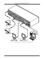
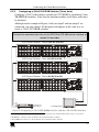
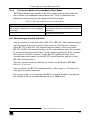
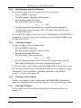
6.1 Connecting the VS-3232Vxl as a Composite Video Switcher
To install the VS-3232Vxl as illustrated in the example in Figure 3, do the
following1:
1. Connect up to 32 composite video sources (for example2, two composite
video players).
2. Connect up to 32 composite video acceptors (for example2, two displays).
3. Set the dipswitches (see section 6.2.3).
4. If required, connect a PC and/or controller to the RS-232 port (see
section 6.4.1) and/or the RS-485 port (see section 6.4.2) and/or the
ETHERNET port (see section 6.6).
5. Connect the power cord3.
6. If necessary, review and set the system variables, using the MENU function,
and the default setup (UNITY setting) as section 8 describes.
1 Switch OFF the power on each device before connecting it to your VS-3232Vxl
2 In this example only two inputs and two outputs are connected
3 We recommend that you use only the power cord that is supplied with this machine
11
Connecting the Video Matrix Switcher
Figure 3: Configuring the VS-3232Vxl for Composite Video
12
KRAMER: SIMPLE CREATIVE TECHNOLOGY
Connecting the Video Matrix Switcher
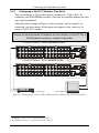
6.2 Assembling a Multi-channel Video Switcher
You can configure several VS-3232Vxl units as 32x32 multi-channel video
switchers for:
s-Video (Y/C) by combining two VS-3232Vxl units (see section 6.2.1)
YUV (RGB) by combining three VS-3232Vxl units (see section 6.2.2)
RGBS by combining four VS-3232Vxl units (see section 6.2.3)
In a multi-channel video switcher configuration, only one unit can be the
Master (with DIP 6 OFF). The other units must be Slaves (with DIP 6 ON).
The front panel of each Slave unit is always locked and its LCD display does
not illuminate, although it displays the current cross-point status of those
switchers. The Slave units always follow the Master. The Master unit operates
in the regular way1, leading the Slaves in the background.
To activate a multi-channel video switcher so that each unit is in the same
state from the outset, first turn ON the master unit and only after it completes
the initial setup, turn ON the slave units one by one.
1 The front panel is not locked and the LCD display illuminates
13
Connecting the Video Matrix Switcher
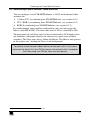
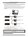
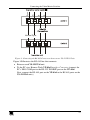
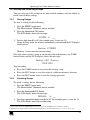
6.2.1
Configuring a 32x32 Y/C Switcher (Two Units)
You can configure a 32x32 video matrix switcher for s-Video (Y/C), by
combining two VS-3232Vxl switchers. Note that the machine number on both
units must be identical.
Although in the example in Figure 4 only one input1 and one output2 are
connected, you can connect all the inputs and outputs in the same way to
create a 32x32 Y/C switcher.
Connect the communication line between the two switchers via the RS-232 or
RS-485 control interface as section 6.4 describes.
Y Channel Switcher - Master (Set DIP 6 to OFF)
C Channel Switcher - Slave (set DIP 6 to ON)
C
Y
Y
C
s-Video Player
s-Video Display
Figure 4: Configuring a 32x32 s-Video (YC) Switcher with two VS-3232Vxl Switchers
1 The INPUT 1 connectors on the Y switcher and the C switcher
2 The OUTPUT 32 connectors on the Y switcher and the C switcher
14
KRAMER: SIMPLE CREATIVE TECHNOLOGY
Connecting the Video Matrix Switcher
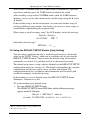
6.2.2
Configuring a 32x32 YUV/RGB Switcher (Three Units)
Configure a 32x32 video matrix switcher for YUV/RGB by combining1 three
VS-3232Vxl switchers. Note that the machine number on all three units must
be identical.
Although in the example in Figure 5 only one input2 and one output3 are
connected, you can connect all the inputs and outputs in the same way to
create a 32x32 YUV/RGB switcher.
Connect the communication line via the RS-232 or RS-485 control interface as
section 6.4 describes.
Y/G Channel Switcher - Master (Set DIP 6 to OFF)
U/B Channel Switcher - Slave (Set DIP 6 to ON)
V/R Channel Switcher - Slave (Set DIP 6 to ON)
V/R
V/R
U/B
Y/G
U/B
Component
Video Player
Y/G
YUV/RGB Display
Figure 5: Configuring a 32x32 YUV (RGB) Switcher with three VS-3232Vxl Switchers
1 For a description of how to connect the RS-485 connectors between the VS-3232Vxl switchers, refer to section 6.4.2
2 The INPUT 1 connectors on the Y switcher, the U switcher and the V switcher
3 The OUTPUT 32 connectors on the Y switcher, the U switcher and the V switcher
15
Connecting the Video Matrix Switcher
6.2.3
Configuring a 32x32 RGBS Switcher (Four Units)
Configure four VS-3232Vxl switchers as a 32x32 video matrix switcher for
RGBS1, in a similar way to how Figure 5 in section 6.2.2 illustrates combining
three VS-3232Vxl switchers for YUV (RGB).
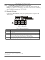
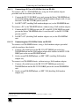
6.3 Dipswitch Settings
Configure the VS-3232Vxl by setting the eight dipswitches as Figure 6 and
Table 3 define:
SYSTEM MODE SLAVE MODE
RS-232 NULL-MODEM
MACHINE #
RS-485 TERMINATION
Figure 6: Dipswitches
Table 3: Dipswitch Definitions
Dipswitch #
1-4
5
6
7
8
Function:
Set the MACHINE # (see Table 4 in section 6.3.1)
Enables (ON) or disables (OFF) the FOLLOW SYSTEM MODE in a multi-switcher
configuration
Enables (ON) or disables (OFF) the SLAVE mode in a multi-channel configuration
Disables the use of a null modem adapter2 with RS-232 as follows:
Set OFF for RS-232 input connection via a null modem adapter
Set ON for RS-232 input connection without a null modem adapter
Set ON for RS-485 termination for the first and the last machine (RS-485 line
terminates with 110 ); for others set OFF (RS-485 line is open)
1 The S signal must be composite video SYNC (analog), not TTL
2 See section 6.4.1
16
KRAMER: SIMPLE CREATIVE TECHNOLOGY
Connecting the Video Matrix Switcher
6.3.1
Setting the MACHINE #
To control a unit remotely via RS-232, RS-485, IR or the Ethernet, each unit
has to be identified via its unique Machine #. Set the Machine #1 on a
VS-3232Vxl unit according to Table 4.
Table 4: Machine # Dipswitch Settings
Mach. #
1
2
3
4
5
6
7
8
6.3.2
DIP 1
ON
OFF
ON
OFF
ON
OFF
ON
OFF
DIP 2
OFF
ON
ON
OFF
OFF
ON
ON
OFF
DIP 3
OFF
OFF
OFF
ON
ON
ON
ON
OFF
DIP 4
OFF
OFF
OFF
OFF
OFF
OFF
OFF
ON
Mach. #
9
10
11
12
13
14
15
DIP 1
ON
OFF
ON
OFF
ON
OFF
ON
DIP 2
OFF
ON
ON
OFF
OFF
ON
ON
DIP 3
OFF
OFF
OFF
ON
ON
ON
ON
DIP 4
ON
ON
ON
ON
ON
ON
ON
Understanding the System Mode
Though the terms audio-follow-video2 and audio breakaway3 are well known,
there may be signals other than audio signals that need to be switched
simultaneously and at other times, need to be switched independently.
For example:
Non-linear editing systems that combine video with analog audio or with
digital audio
Duplication systems, that produce Master tapes from programs with
different formats such as composite analog, component analog and
component digital
The term FOLLOW-SYSTEM4 indicates the most common case where
any type of signal can follow one or more other signals.
DIP 5 defines whether the VS-3232Vxl unit can communicate with other
switchers via a common control line.
You can set DIP 5 OFF to disable the FOLLOW-SYSTEM mode when
setting a standalone switcher5 application, including standalone multichannel video switcher applications6.
1 When using a single unit, set the unit to MACHINE # 1
2 Video and the audio channels switch simultaneously in the same way
3 Audio channels switch independently from the video channels
4 Instead of Audio-Follow-Video
5 See section 6.1
6 See section 6.2
17
Connecting the Video Matrix Switcher
You must set DIP 5 ON to enable the FOLLOW-SYSTEM mode in an
interconnected varied-format switcher application.
You must set the machine number on each machine to a different value.
Refer to section 7.7 for a description of the FOLLOW-SYSTEM and
BREAKAWAY-FROM- SYSTEM modes MENUs.
6.3.3
Understanding the Slave Mode
The SLAVE mode is only used for the multi-channel video switcher
configuration, for example, when using three VS-3232Vxl units to form a
YUV or an RGB switcher, as Figure 5 illustrates. One unit is used as the
Master, and the other two units are Slaves. The Slaves always follow the
Master. In the example illustrated in Figure 5, the first VS-3232Vxl unit is the
Master (with DIP 6 set OFF enabling the Master mode) and the second and
third VS-3232Vxl units are Slaves (with DIP 6 set ON enabling the Slave
mode).
On all three machines the machine number must be set to the same value.
On both Slave VS-3232Vxl units, the LCD display1, shows the following
message:
However, the display on each Slave VS-3232Vxl unit dynamically shows2 all
the changes that were made in the Master VS-3232Vxl unit.
The front panel control is managed via the Master VS-3232Vxl unit, on which
the front panel buttons are unlocked and the LCD display illuminates.
1 At the time of powering the machines ON
2 Albeit with an LCD Display that does not illuminate
18
KRAMER: SIMPLE CREATIVE TECHNOLOGY
Connecting the Video Matrix Switcher
6.3.4
The System Mode versus the Master/Slave Mode
The Follow mode seems similar to the Slave mode since in both modes the
unit switches via commands from another unit. Table 5 summarizes the
differences between the System mode and the Slave mode:
Table 5: The System Mode versus the Slave Mode
System Mode
The unit can be switched in the Follow or Breakaway
mode at any time, depending on the current application
requirements.
Any unit can be turned on or off at any time.
Slave Mode
The unit always follows the Master. It cannot be set in
the breakaway (stand-alone) mode without turning off
and rewiring.
The Slave unit can be turned ON only after full
initialization of the Master unit.
6.4 Connecting a Control Interface
You can connect a control interface (RS-232 or RS-485). The control interface
must be identical on each switcher in the series of 32x32 matrix switchers;
either RS-232 or RS-485. One control interface suffices. Do not use both
RS-232 and RS-485 control interfaces in the same configuration. For example,
in an interconnected varied-format 32x32 switcher application, if the switcher
that connects to the PC connects via the RS-232 control interface, each
switcher must interconnect via the RS-232 control interface and not via the
RS-485 control interface.
You may transfer from one interface to another via the Kramer VP-43xl
Interface Converter1.
You can choose the RS-232 control interface, if the range is < 25 meters for
each point-to-point connection.
For greater ranges, you can choose the RS-485 control interface, and operate
the switcher from an extended distance of up to 1000 meters.
1 For more information on the VP-43xl, go to our Web site at http://www.kramerelectronics.com
19
Connecting the Video Matrix Switcher
6.4.1
Connecting the RS-232 Control Interface
You can connect several switchers (from the series of 32x32 or 16x16 matrix
switchers) and the control unit in an RS-232 daisy chain arrangement, with or
without using a Null-modem adapter, as Figure 7 illustrates.
The RS-232 daisy chain switcher arrangement is transparent. This lets you arrange
the switchers (from the series of 32x32 or 16x16 matrix switchers) according to
your requirements, and not according to a fixed sequence dependent on the
Machine #.
With a Null-modem adapter
Set DIP 7 OFF
With a Null-modem adapter
Set DIP 7 OFF
Without a Null-modem adapter
Set DIP 7 ON
Figure 7: Connecting a PC to Three VS-3232Vxl Units
You can connect any of the following:
The PC’s DB9 COM port to a VS-3232Vxl unit1 (see section 6.4.1.1)
Two VS-3232Vxl units1, (see section 6.4.1.2)
Important: powering OFF a unit inside the daisy-chain will destroy the daisychain connection.
1 With or without the Null-modem adapter
20
KRAMER: SIMPLE CREATIVE TECHNOLOGY
Connecting the Video Matrix Switcher
6.4.1.1
Connecting a PC to a VS-3232Vxl Unit via RS-232
To connect a PC to a VS-3232Vxl unit, using the Null-modem adapter
provided with the machine (the default):
1. Connect the RS-232 IN DB9F rear panel port on the Master VS-3232Vxl unit
to the Null-modem adapter and connect the Null-modem adapter with a 9-wire
flat cable1 to the RS-232 DB9 port on your PC.
2. Set DIP 7 OFF2 (enabling Null-modem adapter use) on the VS-3232Vxl unit.
To connect a PC to the VS-3232Vxl unit, without using a Null-modem adapter:
1. Connect the RS-232 DB9 port on your PC to the RS-232 IN DB9F rear panel
port on the Master VS-3232Vxl with a 9-wire flat cable1 to the RS-232 DB9
port on your PC.
2. Set DIP 7 ON2 (disabling Null-modem adapter use) on the VS-3232Vxl
unit.
6.4.1.2
Connecting two VS-3232Vxl Units via RS-232
To connect two VS-3232Vxl units, using a Null-modem adapter provided
with the machine (the default):
1. Connect a flat cable between the RS-232 OUT DB9M port on the first
VS-3232Vxl unit and the Null-modem adapter that attaches to the RS-232 IN
DB9F port on the second VS-3232Vxl unit.
2. On the second VS-3232Vxl unit, set DIP 7 OFF2 (enabling Null-modem
adapter use).
To connect two VS-3232Vxl units, without using a Null-modem adapter:
1. Connect a flat cable between the RS-232 OUT DB9M port on the first
VS-3232Vxl unit and the RS-232 IN DB9F port on the second VS-3232Vxl
unit.
2. On the second VS-3232Vxl unit, set DIP 7 ON (disabling Null-modem
adapter use).
1 The flat cable should consist of at least three straight-through wires for PINs 2, 3 and 5
2 See section 6.2.3
21
Connecting the Video Matrix Switcher
6.4.2
Connecting the RS-485 Control Interface
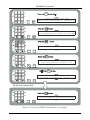
Figure 8 defines the RS-485 connector PINOUT for external RS-485 control.
The RS-485 connector is also used (if required) for vertical sync:
Figure 8: RS-485 Connector PINOUT
To connect an RS-485 connector on one VS-3232Vxl unit to an RS-485
connector on one or more other switchers (from the series of 32x32 or 16x16
matrix switchers), as Figure 9 illustrates:
1. Connect the “A” PIN on the first VS-3232Vxl unit to the “A” PIN on the
second VS-3232Vxl unit and all the other units.
2. Connect the “B” PIN on the first VS-3232Vxl unit to the “B” PIN on the
second VS-3232Vxl unit and all the other units.
3. If shielded cable is used for an RS-485 connection, you may connect the shield
to the “G” (ground) PIN.
For details about how to configure the vertical sync (if required), refer to
section 6.5 and section 8.1.
22
KRAMER: SIMPLE CREATIVE TECHNOLOGY
A
B
G
Sync
Connecting the Video Matrix Switcher
Vertical Sync
Figure 9: Connecting the RS-485 Connectors between two VS-3232Vxl Units
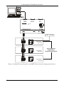
Figure 10 illustrates the RS-485 line that connects:
Between each VS-3232Vxl unit
To the PC via a Kramer Tools VP-43xl Interface Converter (connect the
PC’s DB 9 COM port to the RS-232 IN DB9F port on the VP-43xl.
Next, connect the RS-485 port on the VP-43xl to the RS-485 ports on the
VS-3232Vxl units)
23
Connecting the Video Matrix Switcher
EXT SYNC
MACHINE # 1
DIP 8 OFF
MACHINE # 1
DIP 8 OFF
32x32 Component
Video Switcher
(Three VS-3232Vxl Units)
MACHINE # 1
DIP 8 ON
Figure 10: RS-485 Control Interface and SYNC Connections for Component Switcher
24
KRAMER: SIMPLE CREATIVE TECHNOLOGY
Connecting the Video Matrix Switcher
6.5 Configuring the Sync
You can configure the method of the switching between the video sources in
the VS-3232Vxl. The switching (transition) is done according to the selection
of the SYNC input:
An EXTERNAL Sync (the GENLOCK BNC connector)
The INPUT # 1 BNC connector, or
An EXT-SYS SYNC1 (a sync derived from another 32 or 16 series
switcher) via the RS-485 sync Terminal Block connector2
You can also set the machine to the immediate switching mode, in which
switching is executed immediately after receiving the command. This mode is
not a glitch-free transition
Configure the sync via the SYNC Configuration Menu command setting3.
When setting up for example, a 32x32 YUV switcher, linking a common sync
to all the machines may be necessary to facilitate simultaneous vertical
interval switching.
Usually, the easiest method is to choose the sync source from the first
machine (for example, the Y unit in a 32x32 YUV switcher configuration, as
section 6.2.2 describes) and then connect all the terminal block connectors4, as
Figure 10 illustrates.
In this case, set the first machine to select the sync source from the external
sync connector or from the INPUT # 1 connector. This sync is now available
to the other machines via the RS-485 terminal block connector, as Figure 8,
Figure 9 and Figure 10 illustrate. Select the EXT-SYS SYNC5 on the other
machines that receive that sync.
1 External system sync
2 When using multiple machines in one system
3 Refer to section 8.1
4 Alternatively, you can use the GENLOCK BNC connectors on the rear panel
5 You can also select the immediate switching mode, in which the switching operation is executed immediately after
receiving the command. This mode is not a glitch free transition
25
Connecting the Video Matrix Switcher
6.6 Controlling via the ETHERNET
You can connect the VS-3232Vxl via the Ethernet, using a crossover cable
(see section 6.6.1) for direct connection to the PC or a straight through cable
(see section 6.6.2) for connection via a network hub or network router1.
6.6.1
Connecting the ETHERNET Port directly to a PC (Crossover Cable)
You can connect the Ethernet port of the VS-3232Vxl to the Ethernet port on
your PC, via a crossover cable with RJ-45 connectors.
This type of connection is recommended for identification of the factory default
IP Address of the VS-3232Vxl during the initial configuration
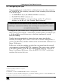
After connecting the Ethernet port, configure your PC as follows:
1. Right-click the My Network Places icon on your desktop.
2. Select Properties.
3. Right-click Local Area Connection Properties.
4. Select Properties.
The Local Area Connection Properties window appears.
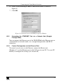
5. Select the Internet Protocol (TCP/IP) and click the Properties Button (see
Figure 11).
Figure 11: Local Area Connection Properties Window
1 After connecting the Ethernet port, you have to install and configure your Ethernet Port. For detailed instructions, see the
“Ethernet Configuration (FC-11) guide.pdf” file in the technical support section on our Web site:
http://www.kramerelectronics.com
26
KRAMER: SIMPLE CREATIVE TECHNOLOGY
Connecting the Video Matrix Switcher
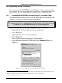
6. Select Use the following IP Address, and fill in the details as shown in
Figure 12.
7. Click OK.
Figure 12: Internet Protocol (TCP/IP) Properties Window
6.6.2
Connecting the ETHERNET Port via a Network Hub (StraightThrough Cable)
You can connect the Ethernet port of the VS-3232Vxl to the Ethernet port on
a network hub or network router, via a straight-through cable with RJ-45
connectors.
6.6.3
Control Configuration via the Ethernet Port
To control several units via the Ethernet, connect the Master unit
(Machine # 1) via the Ethernet port to the LAN port of your PC. Use your PC
initially to configure the settings (see section 6.6).
27
Operating Your Video Matrix Switcher
7
Operating Your Video Matrix Switcher
This section describes:
The startup display (see section 7.1)
How to use the selector buttons (see section 7.2)
How to confirm actions (see section 7.3)
The switching options (see section 7.4)
How to store and recall setups (see section 7.5)
The DEFAULT SETUP button (see section 7.6)
How to Choose the FOLLOW or the BREAKAWAY modes (see
section 7.7)
How to Lock and unlock the front panel (see section 7.8)
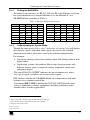
7.1 Startup Display
After switching on the power, the LCD display1 shows the following screens
in sequence:
!
"# $ "#
%
$
&&&
'(
'(
'#
'#
'"
'"
')
')
'*
'*
'+
'+
',
',
''-
'.
'.
('
('
((
((
(#
(#
("
("
Figure 13: Default Startup Status Display Sequence
The VS-3232Vxl does not have separate output and input pushbuttons.
Instead, the front panel includes a numerical keyboard within the Selector
Buttons area2. This keyboard that includes the numbers from 0 to 9, lets you
enter both the output and input numbers.
1 The text in the LCD Display may vary (according to machine settings)
2 See Table 1
28
KRAMER: SIMPLE CREATIVE TECHNOLOGY
Operating Your Video Matrix Switcher
7.1.1
Viewing the Display
Figure 13 shows the output-input cross-points on the LCD display. The LCD
display can show only 13 input/output combinations at a time from the
available 32.
By shifting the contents of the display to the right or to the left, via the or
the buttons on the front panel, respectively, you can view the full contents
of the display.
This function is enabled when:
The switcher is in between operations1
Recalling a setup using the or buttons
When entering an OUT IN combination, the contents of the LCD display
automatically shift to indicate the current status of the selected output.
7.2 Using the Selector Buttons
Since the VS-3232Vxl has 32 inputs and outputs (and up to 59 setups that can
be recalled), it can handle two digit numbers as well as one digit numbers (for
numbers under 10). When entering a one-digit number (for example 5), you
can either press 0 followed by 5 or 5 followed by ENT.
The number 00 (or 0, ENT) is relevant for the input only and is used to
disconnect the currently entered output number from the input.
The ESC button is used to cancel an operation without affecting the current
status of the switcher. For example, if a wrong number is entered, press the
ESC button to cancel the operation. The ESC button can also be used for
cancelling a store/recall operation or to exit the setup menu at any stage.
7.3 Confirming Actions
You can choose to work in the At Once (the default2) or the Confirm mode.
In the At Once mode (the TAKE button is not illuminated):
Pressing an OUT-IN combination implements the switch immediately
You save time as execution is immediate and actions require no user
confirmation
No protection is offered to correct an erroneous action
1 Waiting for its next operation while all previous operations are complete or cancelled
2 For all actions except storing/recalling
29
Operating Your Video Matrix Switcher
In the Confirm mode (the TAKE button illuminates):
You can key-in an action and then confirm it by pressing the TAKE
button
Every action requires user confirmation, protecting against erroneous
switching
Execution is delayed until the user confirms the action1
7.3.1
Toggling between the At Once and Confirm Modes
To toggle between the At Once and Confirm modes, do the following:
1. Press the TAKE button to toggle between the At Once mode (in which the
TAKE button does not illuminate) and the Confirm mode (in which the
TAKE button illuminates).
Actions now require user confirmation and the TAKE button illuminates.
2. Press the illuminated TAKE button to toggle from the Confirm mode back to
the At Once mode.
Actions no longer require user confirmation and the TAKE button no longer
illuminates.
You can toggle between the At Once and Confirm modes at any time, unless
the TAKE button blinks.
7.3.2
Confirming a Switching Action
To confirm a switching action (in the Confirm mode), do the following:
1. Press an OUT-IN combination.
The TAKE button blinks.
2. Press the blinking TAKE button to confirm the action.
Once the action is executed, the TAKE button illuminates once again.
7.4 Switching Options
You can switch:
One input to one output (see section 7.4.1)
Several inputs to several outputs (see section 7.4.2)
One input to all outputs (see section 7.4.3)
1 Failure to press the TAKE button within half minute (the Timeout) will abort the action
30
KRAMER: SIMPLE CREATIVE TECHNOLOGY
Operating Your Video Matrix Switcher
7.4.1
Switching one Input to one Output
To switch one input to one output (in the At Once mode):
1. Press the appropriate digit buttons (for example, 06 representing output 6).
The LCD display shows the following on the right side:
/ / 01
'+
The left-hand side of the display shows a segment of the input-output display,
automatically shifting the content to show the 06 output.
2. Press the appropriate input number (for example, 27 representing input 27):
When in the At Once mode, the switching takes place immediately
and the LCD display shows a segment of the input-output status,
including the switched input and output (for example 06-27)
When in the Confirm mode, the LCD display shows the following:
#, 01
'+
Press the blinking TAKE button to switch the input to the output
7.4.2
Switching several Inputs to several Outputs
In the At Once mode, the VS-3232Vxl will execute each OUT-IN
combination separately (see section 7.4.1). If you want to switch several
inputs to several outputs it is necessary to operate the machine in the Confirm
mode.
In the Confirm mode you can key-in several actions and then confirm them by
pressing the TAKE button once (simultaneously switching several inputs to
several outputs).
To switch several inputs to several outputs in the Confirm mode (the TAKE
LED is illuminated), do the following:
1. Press the appropriate digit buttons for an out-in combination.
The TAKE button blinks.
Key-in additional output-input combinations.
The LCD display can show up to five keyed-in actions, as follows1:
'. 01 '+
'* 01 ',
2. After completing the output-input switching sequence, press the blinking
TAKE button to carry out the switching operation.
The inputs switch to the respective outputs, as shown on the LCD display and
the TAKE LED no longer blinks and remains illuminated.
1 In this example, input 9 is set to switch to output 06 and input 5 is set to switch to output 7
31
Operating Your Video Matrix Switcher
7.4.3
Switching one Input to all Outputs
To switch one input to all the outputs (in the At Once mode):
1. Press the MENU button once.
The Menu buttons1 illuminate and are enabled.
2. Press the illuminated ALL button.
The LCD display shows the message:
// 01
3. Press the appropriate digit buttons (for example, 09 representing input 9).
All the outputs switch to this input. The LCD display shows all the outputs
switched to the input 9.
To switch all the outputs to one input in the Confirm mode (the TAKE LED is
illuminated), repeat the steps above and then press the blinking TAKE button
to confirm the action.
7.4.4
Clearing an Output
To clear an output (in the At Once mode):
1. Press the MENU button once.
The Menu buttons1 illuminate and are enabled.
2. Press the illuminated OFF button.
The LCD display shows the message:
// 01
3. Press the appropriate digit buttons (for example, 25 representing output 25).
This output is cleared (there is no input switched to this output).
To clear an output in the Confirm mode (the TAKE LED is illuminated), repeat
the steps above and then press the blinking TAKE button to confirm the action.
Alternatively, you can perform a switching operation as described in
section7.4.1 and set the input to 00.
7.4.5
Clearing several Outputs
To clear several outputs in the Confirm mode (the TAKE LED is illuminated),
repeat the switching actions described in section 7.4.2 but set all the inputs to 00:
7.4.6
Clearing all Outputs
All the outputs can be cleared only through the configuration menu (see
section 8.8).
1 The ALL, OFF, STO and RCl buttons
32
KRAMER: SIMPLE CREATIVE TECHNOLOGY
Operating Your Video Matrix Switcher
7.5 Storing and Recalling Setups
You can store up to 59 settings in the non-volatile memory with the ability to
recall each of those settings.
7.5.1
Storing Setups
To store a setting, do the following:
1. Press the MENU button once.
The Menu buttons1 illuminate and are enabled.
2. Press the illuminated STO button.
The LCD display shows the message:
01 //
3. Insert a digit from 01 to 59 (for example, press 1 twice for 11).
In the At Once mode, the action is immediately executed and the LCD display
briefly shows1:
Memory 11 now stores the current setting.
Note that when saving a setup to an already allocated memory, the TAKE
button blinks and the LCD display shows the message:
You can either:
Press the TAKE button to overwrite the existing setup
Press the ESC button to save the setup to a different memory location
Press the ESC button twice to exit the storing operation
7.5.2
Recalling Setups
To recall a setting, do the following:
1. Press the MENU button once.
The Menu buttons1 illuminate and are enabled.
2. Press the illuminated RCL button.
The LCD display shows the message:
20 //
3. Insert the appropriate digits from 01 to 592 (for example, press 1 twice for 11).
The LCD display shows the recalled setup.
1 In the confirm mode, the TAKE blinks and you have to press the TAKE button to confirm the operation
2 When trying to recall a setup beyond 59, the LCD display shows the following message:
*.
33
Operating Your Video Matrix Switcher
When in the CONFIRM mode (the TAKE button is illuminated), repeat the
steps above and then press the TAKE button to confirm the action.
After recalling a setup in the CONFIRM mode, while the TAKE button is
blinking, you can review the content of the recalled setup using the or the
buttons.
If the recalled setup is not the desired one, you can recall another setup by
entering a different setup number, thus letting you review as many setups as
needed before implementing the required setup.
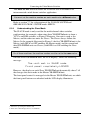
When trying to recall an empty setup1, the LCD display shows the message:
33 4
2
followed by the message :
20 //
7.6 Using the DEFAULT SETUP Button (Unity Setting)
You can select a configuration that is used often and store it as the default
setup (or the UNITY setting), which can be recalled easily by pressing the
DEFAULT SETUP button. You can enter the default setup via the menu
commands (see section 8.5) and then recall it by the touch of a button.
The default setup stores a setup, which is defined via the DEFAULT SETUP
configuration menu (see section 8.5). The default setup includes the switcher
configuration and the cross-points status, or either one of them. The
configuration menu lets you choose what information will be stored (and
recalled accordingly) in the default setup.
If the machine is set to its default setup, the DEFAULT SETUP button
illuminates. Otherwise it is off.
To set the machine to its default setup:
1. Press the DEFAULT SETUP button.
The DEFAULT SETUP button LED blinks and the following message
appears on the LCD display:
5
6
7 8
9
1 That is, a setup # for which no setup is actually stored
2 The same as in step 2 above
34
KRAMER: SIMPLE CREATIVE TECHNOLOGY
Operating Your Video Matrix Switcher
2. Press the DEFAULT SETUP button a second time to recall the default setup.
The DEFAULT SETUP button stops blinking and no longer illuminates, the
TAKE button blinks and the following message appears on the LCD display:
:
9
3. Press the TAKE button to confirm the action or press the ESC button to cancel
the operation.
If the DEFAULT SETUP was recalled, the DEFAULT SETUP button
illuminates.
7.7 Choosing the FOLLOW or the BREAKAWAY Modes
When the VS-3232Vxl functions in the:
FOLLOW-System mode, the VS-3232Vxl switches with other 32x32 or
16x16 matrix switchers, implementing the same action simultaneously
BREAKAWAY-from-System mode, the VS-3232Vxl functions
independently, implementing an action as a stand alone unit that is
independent of the other units connected
The VS-3232Vxl unit will function in the FOLLOW-System mode if at least
one other VS-3232Vxl unit is set to the FOLLOW-System mode and these
units interconnect via an RS-232 and/or RS-485 communication line.
To set the VS-3232Vxl unit to function in the FOLLOW-System mode:
1. Press the FOLLOW button.
The FOLLOW button blinks and the LCD display shows the following
message:
6
;
7 8
<
9
2. Press the FOLLOW button once again.
If there are no switchers online in the FOLLOW-System mode or if one or
more switchers that are in the FOLLOW-System mode are online but their
cross-points status is exactly the same as that of the VS-3232Vxl, the
VS-3232Vxl immediately moves to the FOLLOW System mode.
The FOLLOW stops blinking and then illuminates, the BREAKAWAY
button no longer illuminates and the LCD display restores its last content.
35
Operating Your Video Matrix Switcher
If the cross-points status of the VS-3232Vxl is different from the other online
switchers in the FOLLOW-System mode, the FOLLOW button stops blinking
and the TAKE button blinks, and the LCD display shows the following
message:
9
8
:
:
$
:
=
3. Press the TAKE button.
The VS-3232Vxl moves to the FOLLOW-System mode. The FOLLOW
button illuminates, the BREAKAWAY button no longer illuminates, the
cross-points change according to the status in the system, and the LCD display
shows the new cross point settings.
To set the VS-3232Vxl unit to function in the BREAKAWAY-from-System
mode:
1. Press the BREAKAWAY button.
The BREAKAWAY button blinks and the LCD display shows the following
message:
6
7 8
9
2. Press the BREAKAWAY button once again.
The switcher moves to the BREAKAWAY mode. The BREAKAWAY
button illuminates, the FOLLOW button no longer illuminates and LCD
display restores it last content
7.8 Using the LOCK Button
To prevent changing the settings accidentally or tampering with the unit via
the front panel buttons, lock1 your VS-3232Vxl. Unlocking releases the
protection mechanism.
To toggle the status of the machine, press and hold the LOCK button.
1 Nevertheless, even though the front panel is locked you can still operate via RS-232 or RS-485 serial (remote controller or PC)
36
KRAMER: SIMPLE CREATIVE TECHNOLOGY
The MENU Commands
8
The MENU Commands
The menu lets you configure the VS-3232Vxl to best suit your needs.
To enter the configuration menu, press the menu button twice. The MENU
button illuminates. And the following message appears on the LCD display:
9 :
5
%
>
:
When browsing through the configuration menu, the enabled buttons are
illuminated.
The ESC button is not illuminated, but is always enabled.
Use the configuration menu as follows:
1. Press the MENU button to scroll through the menu items1.
2. Press the ENT button to enter the options in a desired setup.
3. After entering a setup, you can select between several options.
Select a setup option by pressing one of the illuminated buttons in the Selector
Buttons area.
After selecting the desired option, a description of the desired change appears
on the LCD display and the TAKE button blinks.
4. Press the blinking TAKE button to execute the change.
A description of the current state appears on the LCD display for about a
second and then the unit automatically switches to the next item in the menu.
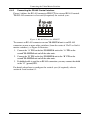
In the example, illustrated in Figure 14, the SYNC configuration is changed
through the configuration menu. You can scroll through the menu items by
pressing the menu button, until you reach the desired item.
1 The LCD display shows the current status of the selected menu item
37
The MENU Commands
1
2
3
4
5
6
7
8
9
MENU
9 :
5
0
TAKE
1
2
3
4
5
6
7
8
9
%
>
:
MENU
MENU
0
<
TAKE
1
2
3
4
5
6
7
8
9
0
2
3
4
5
6
7
8
9
#?
3( "? @ =A
@ =A
)? @ = <
/
MENU
4
9
0
9
MENU
(?
TAKE
1
9 :
=
<
?7
<
TAKE
7
%
>
:
9
/
MENU
Button blinks
1
2
3
4
5
6
7
8
9
TAKE
7
0
%
TAKE
<
%
9
MENU
To the next menu item
1
2
3
4
5
6
7
8
9
MENU
0
?
TAKE
)-*=
9 :
=
=
MENU
Figure 14: Setting the SYNC Configuration (an example)
38
KRAMER: SIMPLE CREATIVE TECHNOLOGY
The MENU Commands
The configuration menu includes the following items:
SYNC configuration (see section 8.1)
INTERFACE configuration (see section 8.2)
Interface REPLY configuration (see section 8.3)
PROTOCOL configuration (see section 8.4)
DEFAULT setup configuration (see section 8.5)
Store DEFAULT setup (see section 8.6)
Indication of the current Firmware version (see section 8.7)
TOTAL RESET options (see section 8.8)
8.1 Selecting the SYNC Configuration
Table 6 summarizes the SYNC configuration options:
Table 6: SYNC Configuration Menu
Press:
To select:
NoVIS, for immediate switching
1
INT#1, SYNC extracted from input #1
2
After the change, the LCD displays:
The unit is set for immediate switching
Active SYNC set from input #01
EXT-BNC, SYNC extracted from
Active SYNC set from GENLOCK input
GENLOCK input
EXT-SYS, SYNC received from another unit Active SYNC set from another unit
3
4
8.2 Selecting the INTERFACE Configuration
The INTERFACE configuration menu is a two step menu:
1. Select the type of interface.
2. Turn the interface ON or OFF.
Note that the RS-232 interface is always ON.
Table 7 summarizes the INTERFACE configuration options.
Table 7: INTERFACE Configuration Menu
Press:
To select:
RS485
1
IRremote
2
3
Ethernet
After the change, the LCD displays:
Interface RS-485 now active or, interface RS-485 now off
IR remote now active or, IR remote now off
Network connection now active or network connection now off
39
The MENU Commands
8.3 Selecting the Interface REPLY Configuration
Table 8 summarizes the interface REPLY configuration options:
Table 8: Interface REPLY Configuration Menu
Press:
To select:
Turn reply ON
1
Never REPLY
2
After the change:
All the interfaces that are set to ON accept and execute commands and also reply
All the interfaces that are set to ON accept and execute commands but do not reply
8.4 Selecting the PROTOCOL Configuration
Table 9 summarizes the PROTOCOL configuration options:
Table 9: PROTOCOL Configuration Menu
Press:
To select:
After the change, the LCD displays:
1
HEXadecimal, for setting the protocol to Communication protocol set to HEX KRAMER-2000
1
HEX KRAMER-2000
ASCII, for setting the protocol1 to ASCII – Communication protocol set to ASCII – SIERRA
2
SIERRA
8.5 Selecting the DEFAULT Setup Configuration
Table 10 summarizes the DEFAULT setup configuration options:
Table 10: DEFAULT Setup Configuration Menu
Press:
1
2
3
To select:
Setup+crosspoints
After the change, the LCD Displays:
Store/recall DEFAULT MATRIX setup and cross-points
crosspnts
setups
Store/recall DEFAULT ONLY cross-points
Store/recall DEFAULT only MATRIX setup
8.6 Selecting the store DEFAULT Setup Configuration
This option in the configuration menu lets you store the current setup to the
default setup, so that by pressing the DEFAULT SETUP button on the front
panel you can recall the default setup (so called UNITY setting).
After pressing the ENT button, the TAKE button blinks and the following
message appears on the display:
$
:
<4
9
After pressing the blinking TAKE button, the display shows:
$
:
5
1 See section 11 for a description of the protocols
40
KRAMER: SIMPLE CREATIVE TECHNOLOGY
The MENU Commands
8.7 The Main Firmware Version
The main firmware version menu shows information regarding the latest main
and Ethernet firmware versions, for example:
>
? (&''
? 5
9 :&
:
This information lets you decide whether a firmware upgrade is required.
It is recommended to upgrade the firmware only after consulting with the
Kramer technical support staff
8.8 Selecting the TOTAL RESET Option
The TOTAL RESET options requires you to press the blinking TAKE button
twice for double confirmation. Table 11 summarizes the TOTAL RESET
menu options:
Table 11: Total Reset Menu
Press:
To select:
All outputs OFF, to
1
disconnect all the outputs
Factory default, to the
2
factory default state
After the change, the LCD displays:
MATRIX erased
The Machine resets as follows:
OUT 1 is connected to IN 1, OUT 2 is connected to IN 2 … OUT 31
is connected to IN 31 and OUT 32 is connected to IN 32
The SYNC is extracted from the BNC-Genlock Input
All the interfaces are set to ON
The interface Reply is set to Reply
The interface protocol is set to Hex Kramer-2000
The DEFAULT SETUP is set to Matrix setup and cross-points
41
Flash Memory Upgrade
9
Flash Memory Upgrade
The VS-3232Vxl lets you upgrade both the:
Switcher Microcontroller (see section 9.1)
Ethernet Microcontroller (see section 9.2)
9.1 Switcher Flash Memory Upgrade
The VS-3232Vxl firmware is located in FLASH memory, which can be
upgraded to the latest Kramer firmware version in minutes! The process
involves:
Downloading from the Internet (see section 9.1.1)
Connecting the PC to the RS-232 port (see section 9.1.2)
Upgrading Firmware (see section 9.1.3)
9.1.1
Downloading from the Internet
You can download the up-to-date file1 from the Internet. To do so:
1. Go to our Web site at www.kramerelectronics.com and download the file:
“FLIP_VS3232Vxl.zip” from the Technical Support section.
2. Extract the file: “FLIP_VS3232Vxl.zip” to a folder (for example, C:\Program
Files\Kramer Flash).
3. Create a shortcut on your desktop to the file: “FLIP.EXE”.
9.1.2
Connecting the PC to the RS-232 Port
Before installing the latest Kramer firmware version on a VS-3232Vxl unit,
do the following:
1. Turn the unit OFF.
2. Connect the RS-232 DB9 rear panel port according to section 6.4.1.
3. Push the rear panel FLASH MAIN button through the hole using a small
screwdriver.
4. Switch the unit ON.
Note: this sequence is critical – first push the FLASH MAIN button and then
turn on the unit
1 The files indicated in this section are given as an example only. File names are liable to change from time to time
42
KRAMER: SIMPLE CREATIVE TECHNOLOGY
Flash Memory Upgrade
9.1.3
Upgrading Firmware
Follow these steps to upgrade the firmware:
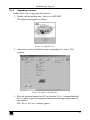
1. Double click the desktop icon: “Shortcut to FLIP.EXE”.
The Splash screen appears as follows:
Figure 15: Splash Screen
2. After a few seconds, the Splash screen is replaced by the “Atmel – Flip”
window:
Figure 16: Atmel – Flip Window
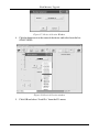
3. Press the keyboard shortcut key F2 (or select the “Select” command from the
Device menu, or press the integrated circuit icon in the upper right corner of
the window).
The “Device Selection” window appears:
43
Flash Memory Upgrade
Figure 17: Device Selection Window
4. Click the button next to the name of the device and select from the list:
AT89C51ED2:
AT89C51ED2
T89C51RD2
Figure 18: Device Selection window
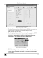
5. Click OK and select “Load Hex” from the File menu.
44
KRAMER: SIMPLE CREATIVE TECHNOLOGY
Flash Memory Upgrade
Figure 19: Loading the Hex
6. The Open File window opens. Select the correct HEX file that contains the
updated version of the firmware for VS-3232Vxl (for example
32M_V1p2.hex) and click Open.
7. Press the keyboard shortcut key F3 (or select the “Communication / RS232”
command from the Settings menu, or press the keys: Alt SCR).
The “RS232” window appears. Change the COM port according to the
configuration of your computer and select the 9600 baud rate:
Figure 20: RS-232 Window
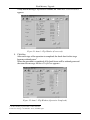
8. Click Connect.
In the “Atmel – Flip” window, in the Operations Flow column, the Run button
is active, and the name of the chip appears as the name of the third column:
AT89C51RD2.
45
Flash Memory Upgrade
Verify that in the Buffer Information column, the “HEX File: VS3232Vxl.hex”
appears.
VS3232Vxl.hex
Figure 21: Atmel – Flip Window (Connected)
9. Click Run.
After each stage of the operation is completed, the check-box for that stage
becomes colored green1.
When the operation is completed, all 4 check-boxes will be colored green and
the status bar message: Memory Verify Pass appears2:
VS3232Vxl.hex
Figure 22: Atmel – Flip Window (Operation Completed)
1 See also the blue progress indicator on the status bar
2 If an error message: “ Not Finished” shows, click Run again
46
KRAMER: SIMPLE CREATIVE TECHNOLOGY
Flash Memory Upgrade
10. Close the “ Atmel –Flip” window.
11. Disconnect the power on the VS-3232Vxl.
12. If required, disconnect the RS-232 rear panel port on the VS-3232Vxl unit
from the Null-modem adapter.
13. Release the FLASH MAIN button on the rear panel.
14. Connect the power to the VS-3232Vxl.
Upon initialization, the new VS-3232Vxl software version shows in the
INPUT STATUS 7-segment Display.
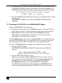
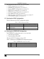
9.2 Ethernet Flash Memory Upgrade
The VS-3232Vxl firmware is located in FLASH memory, which lets you
upgrade to the latest Kramer firmware version in minutes!
The process involves:
Downloading the upgrade package from the Internet
Connecting the PC to the RS-232 port
Upgrading the firmware
9.2.1
Downloading from the Internet
You can download the up-to-date file1 from the Internet. To do so:
1. Go to our Web site at http://www.Kramerelectronics.com and download the
file: “ SetKFRETH11-xx.zip” from the technical support section.
2. Extract the file “ SetKFRETH11-xx.zip” package, which includes the
KFR-Programmer application setup and the .s19 firmware file, to a folder (for
example, C:\Program Files\KFR Upgrade).
3. Install the KFR-Programmer Application.
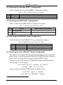
9.2.2
Connecting the PC to the RS-232 Port
Before installing the latest Kramer Ethernet firmware version on the
VS-3232Vxl, do the following:
1. Connect the RS-232 IN DB9 port (COM 1) on the VS-3232Vxl to a Nullmodem adapter and connect the Null-modem adapter with a 9-wire flat cable
to the RS-232 DB9 COM port on your PC.
2. Push the rear panel ETHERNET FLASH button to Program using a small
screwdriver.
3. Connect the power on your machine.
1 File names are liable to change from time to time
47
Flash Memory Upgrade
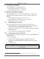
9.2.3
Upgrading Firmware
Follow these steps to upgrade the firmware:
1. Double click the KFR-Programmer desktop icon.
The KFR-Programmer window appears (see Figure 23).
Figure 23: The KFR-Programmer Window
2. Select the required COM Port1.
3. Press the File button to select the .s19 firmware file included in the package.
4. Press the Send button to download the file. The Send button lights red.
5. Wait until downloading is completed and the red Send button turns off.
6. Disconnect the power on the VS-3232Vxl.
7. Release the ETHERNET FLASH button on the rear panel.
8. Connect the power on your machine.
1 To which the VS-3232Vxl is connected on your PC
48
KRAMER: SIMPLE CREATIVE TECHNOLOGY
Technical Specifications
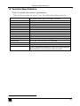
10 Technical Specifications
Table 12 includes the technical specifications:
1
Table 12: Technical Specifications of the VS-3232Vxl Video Matrix Switcher
INPUTS:
32 composite video, 1Vpp / 75
OUTPUTS:
32 composite video, 1Vpp / 75 on BNC connectors
500MHz, -3dB / >50MHz, 0.1dB
<-49dB @5MHz
<0.1%
63dB unweighted / 70dB @5MHz weighted
<0.05% / 0.8Vpp
<0.03 Deg.
<0.05%
19 pushbutton switches; RS-232, RS-485, IR remote, Ethernet
DC
3 modes for Vertical interval switching and Immediate switching
19-inch (W), 7-inch (D) 2U (H) rack-mountable
230 VAC, 50/60Hz, (115VAC, U.S.A.) 10VA
3.5kg (7.8 lbs.) approx
Power cord, Null modem adapter, Windows®-based Kramer control
software, Windows®-based Ethernet Configuration Manager and Virtual
Serial Port Manager, Infra-red remote control transmitter
VIDEO BANDWIDTH:
ALL HOSTILE CROSSTALK:
NON LINEARITY
VIDEO S/N:
DIFF. GAIN:
DIFF. PHASE:
K-FACTOR:
CONTROL:
COUPLING:
SWITCHING:
DIMENSIONS:
POWER SOURCE:
WEIGHT:
ACCESSORIES:
on BNC connectors
1 Specifications are subject to change without notice
49
Communication Protocols
11 Communication Protocols
Using the menu, you can select between the:
Kramer 2000 communication protocol (see section 11.1), or
ASCII Protocol (see section 11.2)
11.1
The Kramer 2000 Communication Protocol
Table 13 and Table 14 include the Protocol 20001 hexadecimal codes2. The
communication parameters are: 9600 baud, with no parity, 8 data bits and 1
stop bit.
1 Full details are available on our Web site: www.kramerelectronics.com
2 This example assumes MACHINE # 1, and node 0
50
KRAMER: SIMPLE CREATIVE TECHNOLOGY
Communication Protocols
Table 13: Hex Table (IN 1-32 to OUT 1-16)
IN
1
OUT
1
OUT
2
OUT
3
OUT
4
OUT
5
OUT
6
OUT
7
OUT
8
OUT
9
IN
2
IN
3
IN
4
IN
5
IN
6
OUT
10
OUT
11
OUT
12
OUT
13
OUT
14
OUT
15
A
B
C
D
E
F
A
B
C
D
E
F
A
B
C
D
E
F
A
B
C
D
E
F
A
B
C
D
E
F
A
B
C
D
E
F
A
B
C
D
E
F
A
B
C
D
E
F
A
B
C
D
E
F
OUT
16
IN
IN
8
IN
IN
10
A
A
A
A
A
A
A
A
A
A
A
A
B
A
C
A
D
A
E
A
F
A
IN
11
B
B
B
B
B
B
B
7
B
B
B
A
B
B
B
C
B
D
B
E
B
F
B
IN
12
C
C
C
C
4
C
C
C
C
C
C
A
C
B
C
C
C
D
C
E
C
F
C
IN
13
D
D
D
D
D
D
D
D
D
D
A
D
B
D
C
D
D
D
E
D
F
D
IN
14
E
E
E
E
E
E
6
E
E
E
E
A
E
B
E
C
E
D
E
E
E
F
E
IN
15
F
F
F
F
F
F
F
F
F
F
A
F
B
F
C
F
D
F
E
F
F
F
A
B
C
D
E
F
9
A
9
B
9
C
9
D
9
E
9
F
IN
16
IN
17
9
9
9
9
9
9
9
9
9
9
51
Communication Protocols
OUT
1
OUT
2
OUT
3
OUT
4
OUT
5
OUT
6
OUT
7
OUT
8
OUT
9
OUT
10
OUT
11
OUT
12
OUT
13
OUT
14
OUT
15
OUT
16
9
9
9
9
9
9
9
9
9
9
A
9
B
9
C
9
D
9
E
9
F
9
IN
19
9
9
9
9
9
9
9
9
9
9
A
9
B
9
C
9
D
9
E
9
F
9
IN
20
9
9
9
9
9
9
9
9
9
9
A
9
B
9
C
9
D
9
E
9
F
9
IN
21
9
9
9
9
9
9
9
9
9
9
A
9
B
9
C
9
D
9
E
9
F
9
IN
22
9
9
9
9
9
9
9
9
9
9
A
9
B
9
C
9
D
9
E
9
F
9
9
9
9
9
9
9
9
9
9
9
A
9
B
9
C
9
D
9
E
9
F
9
9
9
9
9
9
9
9
9
9
9
A
9
B
9
C
9
D
9
E
9
F
9
9
9
9
9
9
9
9
9
9
9
A
9
B
9
C
9
D
9
E
9
F
9
IN
26
9A
9A
9A
9A
9A
9A
9A
9A
9A
9A
A
9A
B
9A
C
9A
D
9A
E
9A
F
9A
IN
27
9B
9B
9B
9B
9B
9B
9B
7
9B
9B
9B
A
9B
B
9B
C
9B
D
9B
E
9B
F
9B
IN
28
9C
9C
9C
9C
4
9C
9C
9C
9C
9C
9C
A
9C
B
9C
C
9C
D
9C
E
9C
F
9C
IN
29
9D
9D
9D
9D
9D
9D
9D
9D
9D
9D
A
9D
B
9D
C
9D
D
9D
E
9D
F
9D
IN
30
9E
9E
9E
9E
9E
9E
6
9E
9E
9E
9E
A
9E
B
9E
C
9E
D
9E
E
9E
F
9E
IN
31
9F
9F
9F
9F
9F
9F
9F
9F
9F
9F
A
9F
B
9F
C
9F
D
9F
E
9F
F
9F
IN
32
A
A
A
A
A
A
A
A
A
A
A
A
B
A
C
A
D
A
E
A
F
A
IN
18
IN
IN
24
IN
52
KRAMER: SIMPLE CREATIVE TECHNOLOGY
Communication Protocols
Table 14: Hex Table (IN 1-32 to OUT 17-32)
IN
1
IN
2
IN
3
IN
4
IN
5
IN
6
OUT
17
OUT
18
OUT
19
OUT
20
OUT
21
OUT
22
OUT
23
OUT
24
OUT
25
OUT
26
OUT
27
OUT
28
OUT
29
OUT
30
OUT
31
OUT
32
9
9
9
9
9
9
9
9
9
9A
9B
9C
9D
9E
9F
A
9
9
9
9
9
9
9
9
9
9A
9B
9C
9D
9E
9F
A
9
9
9
9
9
9
9
9
9
9A
9B
9C
9D
9E
9F
A
9
9
9
9
9
9
9
9
9
9A
9B
9C
9D
9E
9F
A
9
9
9
9
9
9
9
9
9
9A
9B
9C
9D
9E
9F
A
9
9
9
9
9
9
9
9
9
9A
9B
9C
9D
9E
9F
A
9
9
9
9
9
9
9
9
9
9A
9B
9C
9D
9E
9F
A
9
9
9
9
9
9
9
9
9
9A
9B
9C
9D
9E
9F
A
9
9
9
9
9
9
9
9
9
9A
9B
9C
9D
9E
9F
A
A
9
A
9
A
9
A
9
A
9
A
9
A
9
A
9
A
9
A
9A
A
9B
A
9C
A
9D
A
9E
A
9F
A
A
B
9
B
9
B
9
B
9
B
9
B
9
B
97
B
9
B
9
B
9A
B
9B
B
9C
B
9D
B
9E
B
9F
B
A
C
9
C
9
C
9
C
94
C
9
C
9
C
9
C
9
C
9
C
9A
C
9B
C
9C
C
9D
C
9E
C
9F
C
A
D
9
D
9
D
9
D
9
D
9
D
9
D
9
D
9
D
9
D
9A
D
9B
D
9C
D
9D
D
9E
D
9F
D
A
E
9
E
9
E
9
E
9
E
9
E
96
E
9
E
9
E
9
E
9A
E
9B
E
9C
E
9D
E
9E
E
9F
E
A
F
9
F
9
F
9
F
9
F
9
F
9
F
9
F
9
F
9
F
9A
F
9B
F
9C
F
9D
F
9E
F
9F
F
A
9
9
9
9
9
9
9
9
9
9A
9B
9C
9D
9E
9F
A
9
9
9
9
9
9
9
9
9
9
9
9
9
9
9
9
9
9
9
9A
9
9B
9
9C
9
9D
9
9E
9
9F
9
A
IN
IN
8
IN
IN
10
IN
11
IN
12
IN
13
IN
14
IN
15
IN
16
IN
17
53
Communication Protocols
IN
18
IN
19
IN
20
IN
21
IN
22
IN
IN
24
IN
IN
26
IN
27
IN
28
IN
29
IN
30
IN
31
IN
32
54
OUT
17
OUT
18
OUT
19
OUT
20
OUT
21
OUT
22
OUT
23
OUT
24
OUT
25
OUT
26
OUT
27
OUT
28
OUT
29
OUT
30
OUT
31
OUT
32
9
9
9
9
9
9
9
9
9
9
9
9
9
9
9
9
9
9
9
9A
9
9B
9
9C
9
9D
9
9E
9
9F
9
A
9
9
9
9
9
9
9
9
9
9
9
9
9
9
9
9
9
9
9
9A
9
9B
9
9C
9
9D
9
9E
9
9F
9
A
9
9
9
9
9
9
9
9
9
9
9
9
9
9
9
9
9
9
9
9A
9
9B
9
9C
9
9D
9
9E
9
9F
9
A
9
9
9
9
9
9
9
9
9
9
9
9
9
9
9
9
9
9
9
9A
9
9B
9
9C
9
9D
9
9E
9
9F
9
A
9
9
9
9
9
9
9
9
9
9
9
9
9
9
9
9
9
9
9
9A
9
9B
9
9C
9
9D
9
9E
9
9F
9
A
9
9
9
9
9
9
9
9
9
9
9
9
9
9
9
9
9
9
9
9A
9
9B
9
9C
9
9D
9
9E
9
9F
9
A
9
9
9
9
9
9
9
9
9
9
9
9
9
9
9
9
9
9
9
9A
9
9B
9
9C
9
9D
9
9E
9
9F
9
A
9
9
9
9
9
9
9
9
9
9
9
9
9
9
9
9
9
9
9
9A
9
9B
9
9C
9
9D
9
9E
9
9F
9
A
9A
9
9A
9
9A
9
9A
9
9A
9
9A
9
9A
9
9A
9
9A
9
9A
9A
9A
9B
9A
9C
9A
9D
9A
9E
9A
9F
9A
A
9B
9
9B
9
9B
9
9B
9
9B
9
9B
9
9B
97
9B
9
9B
9
9B
9A
9B
9B
9B
9C
9B
9D
9B
9E
9B
9F
9B
A
9C
9
9C
9
9C
9
9C
94
9C
9
9C
9
9C
9
9C
9
9C
9
9C
9A
9C
9B
9C
9C
9C
9D
9C
9E
9C
9F
9C
A
9D
9
9D
9
9D
9
9D
9
9D
9
9D
9
9D
9
9D
9
9D
9
9D
9A
9D
9B
9D
9C
9D
9D
9D
9E
9D
9F
9D
A
9E
9
9E
9
9E
9
9E
9
9E
9
9E
96
9E
9
9E
9
9E
9
9E
9A
9E
9B
9E
9C
9E
9D
9E
9E
9E
9F
9E
A
9F
9
9F
9
9F
9
9F
9
9F
9
9F
9
9F
9
9F
9
9F
9
9F
9A
9F
9B
9F
9C
9F
9D
9F
9E
9F
9F
9F
A
A
9
A
9
A
9
A
9
A
9
A
9
A
9
A
9
A
9
A
9A
A
9B
A
9C
A
9D
A
9E
A
9F
A
A
KRAMER: SIMPLE CREATIVE TECHNOLOGY
Communication Protocols
11.2
ASCII Protocol: General
The ASCII protocol has three basic commands: Y for connect, T for recall, P
for store. Before using the ASCII protocol, you need to select it from the
machine’ s front panel. Press the MENU button until you get to “ set
communication protocol” and then choose the ASCII protocol. This is saved
in the non-volatile memory, so the machine will remain as ASCII even after
cycling power. To check that the protocol has been selected, and to confirm
that the communication is OK, send the string **!! to the VS-3232Vxl. It
should reply by sending the string OK!!
11.2.1
ASCII Protocol: Description
The three basic commands are Y, T, and P.
“Y” command: MAKE A CROSSPOINT CONNECTION.
The format is:
** Y o#, i# !! where i# is the input number, and o# is the output number.
Note: The string does not need a space (spaces are used here just to add clarity
to the explanation).
For example:
**Y3,4!! would connect input 4 to output 3
**Y9,6!! would connect input 6 to output 9
**Y2,17,Y25,12,Y7,6!! would connect input 17 to output 2, input 12 to output
25, and input 6 to output 7.
The buffer allows up to 63 characters. Thus you could place up to about 10
crosspoint connections in a single string.
Also:
**Y0,5!! would connect input 5 to all outputs
**Y3,0!! would disconnect output 3
“T” command: RECALL A SETUP.
The format is:
** T s# !! where s# is the setup number (1 to 59) which is to be recalled.
For example:
**T13!! would recall setup number 13
“P” command: STORE A SETUP.
The format is:
** P s# !! where s# is the setup number (up to 59) where the machine’ s
present status is to be stored.
For example:
**P13!! would store in setup number 13
The reply for all commands could be:
OK!!
or ERROR!!
55
LIMITED WARRANTY
Kramer Electronics (hereafter Kramer) warrants this product free from defects in material and workmanship under the
following terms.
HOW LONG IS THE WARRANTY
Labor and parts are warranted for seven years from the date of the first customer purchase.
WHO IS PROTECTED?
Only the first purchase customer may enforce this warranty.
WHAT IS COVERED AND WHAT IS NOT COVERED
Except as below, this warranty covers all defects in material or workmanship in this product. The following are not covered
by the warranty:
1. Any product which is not distributed by Kramer, or which is not purchased from an authorized Kramer dealer. If you are
uncertain as to whether a dealer is authorized, please contact Kramer at one of the agents listed in the Web site
www.kramerelectronics.com.
2. Any product, on which the serial number has been defaced, modified or removed.
3. Damage, deterioration or malfunction resulting from:
i) Accident, misuse, abuse, neglect, fire, water, lightning or other acts of nature
ii) Product modification, or failure to follow instructions supplied with the product
iii) Repair or attempted repair by anyone not authorized by Kramer
iv) Any shipment of the product (claims must be presented to the carrier)
v) Removal or installation of the product
vi) Any other cause, which does not relate to a product defect
vii) Cartons, equipment enclosures, cables or accessories used in conjunction with the product
WHAT WE WILL PAY FOR AND WHAT WE WILL NOT PAY FOR
We will pay labor and material expenses for covered items. We will not pay for the following:
1. Removal or installations charges.
2. Costs of initial technical adjustments (set-up), including adjustment of user controls or programming. These costs are the
responsibility of the Kramer dealer from whom the product was purchased.
3. Shipping charges.
HOW YOU CAN GET WARRANTY SERVICE
1. To obtain service on you product, you must take or ship it prepaid to any authorized Kramer service center.
2. Whenever warranty service is required, the original dated invoice (or a copy) must be presented as proof of warranty
coverage, and should be included in any shipment of the product. Please also include in any mailing a contact name,
company, address, and a description of the problem(s).
3. For the name of the nearest Kramer authorized service center, consult your authorized dealer.
LIMITATION OF IMPLIED WARRANTIES
All implied warranties, including warranties of merchantability and fitness for a particular purpose, are limited in duration to
the length of this warranty.
EXCLUSION OF DAMAGES
The liability of Kramer for any effective products is limited to the repair or replacement of the product at our option. Kramer shall
not be liable for:
1. Damage to other property caused by defects in this product, damages based upon inconvenience, loss of use of the product, loss
of time, commercial loss; or:
2. Any other damages, whether incidental, consequential or otherwise. Some countries may not allow limitations on how long an
implied warranty lasts and/or do not allow the exclusion or limitation of incidental or consequential damages, so the above
limitations and exclusions may not apply to you.
This warranty gives you specific legal rights, and you may also have other rights, which vary from place to place.
NOTE: All products returned to Kramer for service must have prior approval. This may be obtained from your dealer.
This equipment has been tested to determine compliance with the requirements of:
EN-50081:
EN-50082:
CFR-47:
"Electromagnetic compatibility (EMC);
generic emission standard.
Part 1: Residential, commercial and light industry"
"Electromagnetic compatibility (EMC) generic immunity standard.
Part 1: Residential, commercial and light industry environment".
FCC Rules and Regulations:
Part 15: “ Radio frequency devices
Subpart B Unintentional radiators”
CAUTION!
Servicing the machines can only be done by an authorized Kramer technician. Any user who makes changes or
modifications to the unit without the expressed approval of the manufacturer will void user authority to operate the
equipment.
Use the supplied DC power supply to feed power to the machine.
Please use recommended interconnection cables to connect the machine to other components.
56
.
KRAMER: SIMPLE CREATIVE TECHNOLOGY
For the latest information on our products and a list of Kramer
distributors, visit our Web site: www.kramerelectronics.com,
where updates to this user manual may be found.
We welcome your questions, comments and feedback.
Safety Warning:
Disconnect the unit from the power supply before
opening/servicing.
Caution
Kramer Electronics, Ltd.
Web site: www.kramerelectronics.com
E-mail: [email protected]
P/N: 2900-000325 REV 2