1
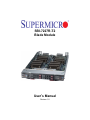
SBI-7227R-T2
Blade Module
User’s Manual
Revison 1.0
SBI-7227R-T2 Blade Module User’s Manual
The information in this User’s Manual has been carefully reviewed and is believed to be accurate. The
vendor assumes no responsibility for any inaccuracies that may be contained in this document, makes no
commitment to update or to keep current the information in this manual, or to notify any person or
organization of the updates. Please Note: For the most up-to-date version of this manual, please see
our web site at www.supermicro.com.
Super Micro Computer, Inc. ("Supermicro") reserves the right to make changes to the product described
in this manual at any time and without notice. This product, including software and documentation, is the
property of Supermicro and/or its licensors, and is supplied only under a license. Any use or reproduction
of this product is not allowed, except as expressly permitted by the terms of said license.
IN NO EVENT WILL SUPERMICRO BE LIABLE FOR DIRECT, INDIRECT, SPECIAL, INCIDENTAL,
SPECULATIVE OR CONSEQUENTIAL DAMAGES ARISING FROM THE USE OR INABILITY TO USE
THIS PRODUCT OR DOCUMENTATION, EVEN IF ADVISED OF THE POSSIBILITY OF SUCH
DAMAGES. IN PARTICULAR, SUPERMICRO SHALL NOT HAVE LIABILITY FOR ANY HARDWARE,
SOFTWARE, OR DATA STORED OR USED WITH THE PRODUCT, INCLUDING THE COSTS OF
REPAIRING, REPLACING, INTEGRATING, INSTALLING OR RECOVERING SUCH HARDWARE,
SOFTWARE, OR DATA.
Any disputes arising between manufacturer and customer shall be governed by the laws of Santa Clara
County in the State of California, USA. The State of California, County of Santa Clara shall be the
exclusive venue for the resolution of any such disputes. Super Micro's total liability for all claims will not
exceed the price paid for the hardware product.
FCC Statement: This equipment has been tested and found to comply with the limits for a Class A digital
device pursuant to Part 15 of the FCC Rules. These limits are designed to provide reasonable protection
against harmful interference when the equipment is operated in a commercial environment. This
equipment generates, uses, and can radiate radio frequency energy and, if not installed and used in
accordance with the manufacturer’s instruction manual, may cause harmful interference with radio
communications. Operation of this equipment in a residential area is likely to cause harmful interference,
in which case you will be required to correct the interference at your own expense.
California Best Management Practices Regulations for Perchlorate Materials: This Perchlorate warning
applies only to products containing CR (Manganese Dioxide) Lithium coin cells. Perchlorate
Material-special handling may apply. See www.dtsc.ca.gov/hazardouswaste/perchlorate for further
details.
WARNING: HANDLING OF LEAD SOLDER MATERIALS USED IN THIS
PRODUCT MAY EXPOSE YOU TO LEAD, A CHEMICAL KNOWN TO THE
STATE OF CALIFORNIA TO CAUSE BIRTH DEFECTS AND OTHER
REPRODUCTIVE HARM.
Manual Revison 1.0
Release Date: July 26, 2012
Unless you request and receive written permission from Super Micro Computer, Inc., you may not copy
any part of this document.
Information in this document is subject to change without notice. Other products and companies referred
to herein are trademarks or registered trademarks of their respective companies or mark holders.
Copyright © 2012 by Super Micro Computer, Inc.
All rights reserved.
Printed in the United States of America
ii
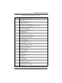
Table of Contents
Chapter 1 Introduction....................................................................... 1-1
1-1 Overview ............................................................................................. 1-1
1-2 Product Checklist of Typical Components..................................... 1-1
1-3 Blade Module Features .................................................................... 1-2
Processors .............................................................................................. 1-2
Memory ................................................................................................... 1-2
Storage.................................................................................................... 1-3
Density .................................................................................................... 1-3
1-4 Contacting Supermicro ..................................................................... 1-4
Chapter 2 System Safety .................................................................. 2-1
2-1 Electrical Safety Precautions........................................................... 2-1
2-2 General Safety Precautions............................................................. 2-2
2-3 Electrostatic Discharge Precautions .............................................. 2-2
2-4 Operating Precautions ...................................................................... 2-2
Chapter 3 Setup and Installation ................................................. 3-1
3-1 Overview ............................................................................................. 3-1
3-2 Installing Blade Modules .................................................................. 3-1
Powering Up a Blade Unit....................................................................... 3-1
Powering Down a Blade Unit .................................................................. 3-1
Removing a Blade Unit from the Enclosure ............................................ 3-2
Removing/Replacing the Blade Cover .................................................... 3-2
Installing a Blade Unit into the Enclosure ............................................... 3-2
3-3 Processor Installation ....................................................................... 3-4
3-4 Onboard Battery Installation ............................................................ 3-9
3-5 Memory Installation ........................................................................... 3-9
Populating Memory Slots ........................................................................ 3-9
DIMM Installation .................................................................................. 3-11
3-6 Hard Disk Drive Installation ........................................................... 3-12
3-7 Installing the Operating System .................................................... 3-13
Installing with an External USB CD-ROM Drive.................................... 3-14
Installing via PXE Boot.......................................................................... 3-14
Installing via Virtual Media (Drive Redirection) ..................................... 3-14
3-8 Management Software ................................................................... 3-15
iii
SBI-7227R-T2 Blade Module User’s Manual
3-9 Configuring and Setting up RAID ................................................. 3-15
Chapter 4 Blade Module Features .............................................. 4-1
4-1 Control Panel ..................................................................................... 4-2
Power Button .......................................................................................... 4-3
KVM Button............................................................................................. 4-3
LED Indicators ........................................................................................ 4-3
KVM Connector....................................................................................... 4-3
4-2 Mainboard........................................................................................... 4-4
Jumpers .................................................................................................. 4-6
CMOS Clear............................................................................................ 4-6
4-3 Blade Unit Components ................................................................... 4-7
Memory Support ..................................................................................... 4-8
Hard Disk Drives ..................................................................................... 4-8
Chapter 5 RAID Setup Procedure ............................................... 5-1
5-1 RAID Configurations ......................................................................... 5-1
5-2 Preparing for Setup ........................................................................... 5-1
5-3 RAID Setup Procedure ..................................................................... 5-2
Enabling SATA RAID in the BIOS ........................................................... 5-2
Using the Intel RAID Utility...................................................................... 5-3
Chapter 6 BIOS ....................................................................................... 6-1
6-1 Introduction......................................................................................... 6-1
System BIOS .......................................................................................... 6-1
How To Change the Configuration Data ................................................. 6-1
Starting the Setup Utility.......................................................................... 6-1
6-2 BIOS Updates .................................................................................... 6-2
Flashing BIOS......................................................................................... 6-2
6-3 Running Setup ................................................................................... 6-3
6-4 Main BIOS Setup............................................................................... 6-4
6-5 Advanced Setup ................................................................................ 6-5
6-6 Event Logs Setup ............................................................................ 6-14
6-7 IPMI Setup ........................................................................................ 6-15
6-8 Boot ................................................................................................... 6-16
6-9 Security ............................................................................................. 6-16
6-10 Save & Exit..................................................................................... 6-17
iv
Table of Contents
Appendix A BIOS POST Codes ....................................................A-1
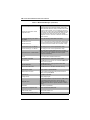
A-1 BIOS POST Messages ....................................................................A-1
A-2 BIOS POST Codes ...........................................................................A-3
Recoverable POST Errors ......................................................................A-4
Terminal POST Errors.............................................................................A-4
v
SBI-7227R-T2 Blade Module User’s Manual
Notes
vi
Preface
About this Manual
This manual is written for professional system integrators, Information Technology
professionals, service personnel and technicians. It provides information for the
installation and use of Supermicro's SBI-7227R-T2 blade module. Installation and
maintenance should be performed by experienced professionals only.
Manual Organization
Chapter 1: Introduction
The first chapter provides a checklist of the main components included with
SBI-7227R-T2 blade module and describes their main features.
Chapter 2: System Safety
You should familiarize yourself with this chapter for a general overview of safety
precautions that should be followed when installing and servicing SBI-7227R-T2 blade
module.
Chapter 3: Setup and Installation
Refer to this chapter for details on installing the SBI-7227R-T2 blade module into the
SuperBlade® chassis. Other sections cover the installation and placement of memory
modules and the installation of hard disk drives into the blade module.
Chapter 4: Blade Module Features
This chapter coves features and component information about SBI-7227R-T2 blade
module. Included here are descriptions and information for mainboard components,
connectors, LEDs and other features of the blade module.
Chapter 5: RAID Setup Procedure
RAID setup and operations for SBI-7227R-T2 blade module are covered in this chapter.
Chapter 6: BIOS
BIOS setup is covered in this chapter for SBI-7227R-T2 blade module.
Appendix A: BIOS POST Codes
BIOS POST Codes for SBI-7227R-T2 blade module are explained in this appendix.
vii
SBI-7427R-T3 Blade Module User’s Manual
Notes
viii
Chapter 1
Introduction
1-1
Overview
This user’s manual covers the SBI-7227R-T2 blade module. This blade module is a
compact self-contained two-node server that connects into a pre-cabled enclosure that
provides power, cooling, management and networking functions. One enclosure for the
SBI-7227R-T2 blade module can hold ten blade units (twenty nodes).
In this manual, “blade system” refers to the entire system (including the enclosure and
blades units), “blade” or “blade unit” refers to a single blade module and “blade
enclosure” is the chassis that the blades, power supplies and modules are housed
within.
Please refer to our web site for information on operating systems that have been
certified for use with the SuperBlade (www.supermicro.com/products/superblade/).
1-2
Product Checklist of Typical Components
Your blade module ships with its B9DRT mainboard already installed in its chassis.
Memory, hard disk drives and the CPU must all be installed by the user after shipment.
See Chapter 3: " Setup and Installation" on page 3-1 for details on installation of these
components.
Aside from the blade module unit itself, the following optional Mezzanine add-on cards
(with InfiniBand Switch) may be ordered for your blade module:
•
AOC-XEH-iN2
•
AOC-IBH-XDD
•
AOC-IBH-XQD
•
AOC-IBH-XQS
•
AOC-IBH-XDS
See the Supermicro website and the SuperBlade Network Modules User’s Manual on
your SuperBlade system’s CD-ROM for more details on these add-on cards.
1-1
SBI-7227R-T2 Blade Module User’s Manual
1-3
Blade Module Features
Table 1-1 lists the main features of the SBI-7227R-T2 blade module. See the
proceeding section for components typically included in a blade system and other
optional components. Specific details for the SBI-7227R-T2 blade module are found in
Chapter 4: " Blade Module Features" on page 4-1.
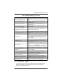
Table 1-1. SBI-7227R-T2 Blade Module Specification Features
Mainboard
B9DRT (proprietary form factor)
Chassis Dimensions (HxWxD): 11.32” x 1.19” x 18.9”
Processors
Supports up to two Intel™ Xeon® E5-2600 series 2011-pin processors per
node. Please refer to our web site for a complete listing of supported
processors.
QPI Speed
QPI up to 8 GT/s
Chipset
Intel C602
Graphics Controller
Integrated Matrox G200eW Graphics
BIOS
128 MB SPI Flash EEPROM with AMI® BIOS each node for each node
Memory Capacity
Each node supports up to 256 GB of RDIMM and 64 GB of UDIMM DDR3
1600/1333/1066 MHz speed SDRAM in eight (8) 240-pin DIMM sockets
SATA Controller
Intel C602 on-chip controller for two Serial ATA drives for each node
Hard Drive Bays
Each node supports two hot-swap drive bays for 2.5" SATA disk/SSD
drives
Processors
Each of the SBI-7227R-T2 blade module’s node supports dual 2011-pin (LGA 2011
Socket R) Intel Xeon E5-2600 series processors.
Refer to the Supermicro web site for a complete listing of supported processors (http://
www.supermicro.com/products/superblade). Please note that you will need to check the
detailed specifications of a particular blade module for a list of the CPUs it supports.
Details on installation of the processor into the SBI-7227R-T2 blade module are found in
Chapter 3: " Setup and Installation" on page 3-1.
Memory
Each of the SBI-7227R-T2 blade module nodes has eight (8) 240-pin DIMM sockets that
can support up to 256 GB RDIMM or 64 GB UDIMM of DDR3 1600/1333/1066 MHz
speed SDRAM. Memory is interleaved, which requires modules of the same size and
speed to be installed in groups (of two or three).
Please refer to the Supermicro web site for a list of supported memory
(www.supermicro.com/products/superblade). The detailed specifications for a blade
module will contain a link to a list of recommended memory sizes and manufacturers.
1-2
Chapter 1: Introduction
Details on installation of memory modules into the SBI-7227R-T2 blade module are
found in Chapter 3: " Setup and Installation" on page 3-1.
Storage
The SBI-7227R-T2 blade module node can have up to two 2.5" SATA (Serial ATA)/SSD
hard disk drives in front-mounted easy removable carriers for a total of four for the whole
module. See Chapter 3: " Setup and Installation" on page 3-1 for storage installation
details.
Density
A maximum of ten blade modules (twenty nodes) may be installed into a single blade
enclosure. Each blade enclosure is a 7U form factor, so a standard 42U rack may
accommodate up to six enclosures with 60 blade modules (120 nodes), or the
equivalent of 120 1U servers. With the inclusion of six CMM modules, twelve Gigabit
Ethernet switches and six InfiniBand switches, this would occupy up to 144U space in a
conventional 1U server configuration.
1-3
SBI-7227R-T2 Blade Module User’s Manual
1-4
Contacting Supermicro
Headquarters
Address:
Super Micro Computer, Inc.
980 Rock Ave.
San Jose, CA 95131 U.S.A.
Tel:
Fax:
+1 (408) 503-8000
+1 (408) 503-8008
[email protected] (General Information)
Email:
[email protected] (Technical Support)
Web Site:
www.supermicro.com
Europe
Address:
Super Micro Computer B.V.
Het Sterrenbeeld 28, 5215 ML
‘s-Hertogenbosch, The Netherlands
Tel:
+31 (0) 73-6400390
Fax:
+31 (0) 73-6416525
[email protected] (General Information)
Email:
[email protected] (Technical Support)
[email protected] (Customer Support)
Asia-Pacific
Address:
Super Micro Computer, Inc.
4F, No. 232-1, Liancheng Rd.
Chung-Ho 235, Taipei County
Taiwan, R.O.C.
Tel:
+886-(2) 8226-3990
Fax:
+886-(2) 8226-3991
Web Site:
www.supermicro.com.tw
Technical Support:
Email:
[email protected]
Tel:
+886-(2) 8226-5990
1-4
Chapter 2
System Safety
2-1
Electrical Safety Precautions
Basic electrical safety precautions should be followed to protect yourself from harm and
the SuperBlade from damage:
•
Be aware of how to power on/off the enclosure power supplies and the individual
blades as well as the room's emergency power-off switch, disconnection switch or
electrical outlet. If an electrical accident occurs, you can then quickly remove power
from the system.
•
Do not work alone when working with high voltage components.
•
Power should always be disconnected from the blade module when removing or
installing such system components as the mainboard, memory modules and
processors.
•
When working around exposed electrical circuits, another person who is familiar
with the power-off controls should be nearby to switch off the power if necessary.
•
Use only one hand when working with powered-on electrical equipment. This is to
avoid making a complete circuit, which will cause electrical shock. Use extreme
caution when using metal tools, which can easily damage any electrical components
or circuit boards they come into contact with.
•
Do not use mats designed to decrease electrostatic discharge as protection from
electrical shock. Instead, use rubber mats that have been specifically designed as
electrical insulators.
•
The power supply power cords must include a grounding plug and must be plugged
into grounded electrical outlets. Power input requires 110-240 VAC, depending upon
your power supply module.
•
Mainboard Battery: This battery must be replaced only with the same or an
equivalent type recommended by the manufacturer (CR2032 Lithium 3V battery).
Dispose of used batteries according to the manufacturer's instructions.
WARNING: There is a danger of explosion if the onboard battery is installed
upside down, which will reverse its polarities.
•
Mainboard replaceable soldered-in fuses: Self-resetting PTC (Positive Temperature
Coefficient) fuses on the mainboard must be replaced by trained service technicians
only. The new fuse must be the same or equivalent as the one replaced. Contact
technical support for details and support.
2-1
SBI-7227R-T2 Blade Module User’s Manual
2-2
General Safety Precautions
Follow these rules to ensure general safety:
•
Keep the area around the SuperBlade clean and free of clutter.
•
Place the blade module cover and any system components that have been removed
away from the system or on a table so that they won't accidentally be stepped on.
•
While working on the system, do not wear loose clothing such as neckties and
unbuttoned shirt sleeves, which can come into contact with electrical circuits or be
pulled into a cooling fan.
•
Remove any jewelry or metal objects from your body, which are excellent metal
conductors that can create short circuits and harm you if they come into contact with
printed circuit boards or areas where power is present.
•
After accessing the inside of the system, replace the blade module's cover before
installing it back into the blade enclosure.
2-3
Electrostatic Discharge Precautions
Electrostatic discharge (ESD) is generated by two objects with different electrical
charges coming into contact with each other. An electrical discharge is created to
neutralize this difference, which can damage electronic components and printed circuit
boards.
The following measures are generally sufficient to neutralize this difference before
contact is made to protect your equipment from ESD:
•
Use a grounded wrist strap designed to prevent static discharge.
•
Keep all components and printed circuit boards (PCBs) in their antistatic bags until
ready for use.
•
Touch a grounded metal object before removing the board from the antistatic bag.
•
Do not let components or PCBs come into contact with your clothing, which may
retain a charge even if you are wearing a wrist strap.
•
Handle a board by its edges only; do not touch its components, peripheral chips,
memory modules or contacts.
•
When handling chips or modules, avoid touching their pins.
•
Put the mainboard and peripherals back into their antistatic bags when not in use.
•
For grounding purposes, make sure the blade enclosure provides excellent
conductivity between the power supplies, the blade modules and the mainboard.
2-4
Operating Precautions
Care must be taken to assure that the cover of the blade unit is in place when the blade
is operating to assure proper cooling. Out of warranty damage to the blade can occur if
this practice is not strictly followed.
Any drive carrier without a hard drive installed must remain fully installed in the drive bay
when the blade module is operating to ensure proper airflow.
2-2
Chapter 3
Setup and Installation
3-1
Overview
This chapter covers the setup and installation of the blade module and its components.
3-2
Installing Blade Modules
Up to ten SBI-7227R-T2 blade modules may be installed into a single blade enclosure.
Blade modules with Windows and Linux operating systems may be mixed together in
the same blade enclosure.
Powering Up a Blade Unit
Each blade unit may be powered on and off independently from the rest of the blades
installed in the same enclosure. A blade unit may be powered up in two ways:
•
Press the power button on the blade unit.
•
Use IPMIView or the web-browser based management utility to apply power using
the CMM module.
Powering Down a Blade Unit
A blade unit may be powered down in either of the following ways:
•
Press the power button on the blade unit.
•
Use IPMIView or the web-browser based management utility to power down (if you
have Operator or Admin privileges on the CMM).
•
Use IPMItool when connected to the CMM to power down (if you have Operator or
Admin privileges on the CMM).
3-1
SBI-7227R-T2 Blade Module User’s Manual
Removing a Blade Unit from the Enclosure
Although the blade system may continue to run, individual blades should always be
powered down before removing them from the enclosure.
Removing a Blade Unit from the Enclosure
1. Power down the blade unit (see "Powering Down a Blade Unit" above).
2. Squeeze both handles to depress the red sections then pull out both handles
completely and use them to pull the blade unit from the enclosure.
NOTE: Blade Modules can be Hot-Plugged from the enclosure.
Removing/Replacing the Blade Cover
The blade cover must be removed to access the mainboard when you need to install or
remove processors, memory units, the onboard battery and so on.
Removing/Replacing the Blade Cover
1. Remove the blade unit from the enclosure (see "Removing a Blade Unit from the
Enclosure" above).
2. Depress the two buttons on the cover while pushing the cover toward the rear of the
blade unit. When it stops, lift the cover off the blade unit.
3. To replace the cover, fit the six grooves in the cover into the studs in the sides of the
blade, then slide the cover toward the front of the blade to lock it into place.
Installing a Blade Unit into the Enclosure
Make sure the cover of the blade unit has been replaced first before installing a blade
unit in the enclosure.
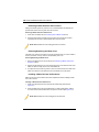
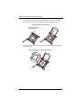
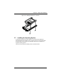
Installing a Blade Unit into the Enclosure
1. Slowly push the blade unit into its bay with the handles fully pulled out (see
Figure 3-1).
2. When the blade stops, push the handles back in to their locked position, making
sure the notches in both handles catch the lip of the enclosure (see Figure 3-2).
NOTE: Blade Modules can be Hot-Plugged into the enclosure.
3-2
Chapter 3: Setup and Installation
WARNING: Use extreme caution when inserting a blade module into the
enclosure. If the blade's power connector becomes damaged, it can damage
pins on other blade bays that it is inserted into.
Figure 3-1. Inserting a Blade into the Enclosure
Figure 3-2. Locking the Blade into Position
3-3
SBI-7227R-T2 Blade Module User’s Manual
3-3
Processor Installation
One or two processors may be installed to the mainboard of each blade unit. See
Chapter 1 for general information on the features of the blade unit and the Supermicro
web site for further details including processor, memory and operating system support.
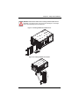
WARNING: This action should only be performed by a trained service
technician. Allow the processor heatsink to cool before removing it.
Removing a Processor
1. Power down and remove the blade unit from the enclosure (see Section 3-2:
Installing Blade Modules on page 3-1 for details).
2. Remove the cover of the blade unit (see "Removing/Replacing the Blade Cover" on
page 3-2).
3. Loosen the four screws that secure the heatsink to the mainboard.
4. Remove the heatsink by gently rotating it back-and-forth sideways with your fingers
to release it from the processor. Set the heatsink aside and upside-down so that
nothing comes into contact with the thermal grease on its underside.
5. Raise the lever of the processor socket up until the processor is released from the
socket, then lift the silver cover plate and remove the processor.
6. Reapply plastic socket covers to the LGA2011 sockets to prevent pin damage.
WARNING: This action should only be performed by a trained service
technician.
3-4
Chapter 3: Setup and Installation
Installing a Processor
WARNING: Warning! When handling the processor package, avoid placing
direct pressure on the label area.
Always connect the power cord last, and always remove it before adding,
removing or changing any hardware components. Make sure that you install the
processor into the CPU socket before you install the CPU heatsink.
Important! If you buy a CPU separately, make sure that you use an
Intel-certified multi-directional heatsink only.
Make sure to install the system board into the chassis before you install the CPU
heatsink.
When receiving a server board without a processor pre-installed, make sure that
the plastic CPU socket cap is in place and none of the socket pins are bent;
otherwise, contact your retailer immediately.
Refer to the Supermicro website for updates on CPU support.
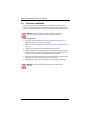
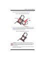
1. There are two load levers on the LGA2011 socket. To open the socket cover, first
press and release the load lever labeled 'Open 1st' (Figure 3-3).
Figure 3-3. Open First Load Lever
WA
R
WA
R
NI
NI
NG
!
OP
OP
NG
!
EN
1
EN
1st
st
Press down on Load
Lever labeled 'Open 1st'.
2. Press the second load lever labeled 'Close 1st' to release the load plate that covers
the CPU socket from its locking position (Figure 3-4).
Figure 3-4. Close First Load Lever
Press down on
Load the Lever
labeled 'Close 1st'
WA
R
NI
OP
WA
RN
IN
G!
NG
!
OP
EN
1
EN
1
st
st
Pull lever away from the socket
3-5
SBI-7227R-T2 Blade Module User’s Manual
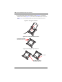
3. With the lever labeled 'Close 1st' fully retracted, gently push down on the 'Open 1st'
lever to open the load plate. Lift the load plate to open it completely (Figure 3-5).
Figure 3-5. Opening the Load Plate
Gently push down to pop
the load plate open.
WA
RN
IN
G!
WA
RN
IN
G!
OP
EN
1st
4. Using your thumb and the index finger, remove the 'WARNING' plastic cap from the
socket (Figure 3-6).
Figure 3-6. Removing the Warning Plastic Cap
WA
R
NIN
G!
3-6
Chapter 3: Setup and Installation
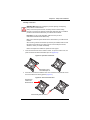
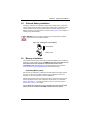
5. Use your thumb and index finger to hold the CPU on its edges. Align the CPU keys,
which are semi-circle cutouts, against the socket keys (Figure 3-7).
Figure 3-7. Aligning CPU Keys with Socket Keys
Socket Keys
CPU Keys
6. Once the keys are aligned, carefully lower the CPU straight down into the socket
(Figure 3-8). Do not drop the CPU on the socket. Do not move the CPU horizontally
or vertically. Do not rub the CPU against the surface or against any pins of the
socket to avoid damaging the CPU or the socket.
Figure 3-8. Lowering the CPU into the Socket
WARNING: You can only install the CPU inside the socket in one direction.
Make sure that the CPU is properly inserted into the CPU socket before closing
the load plate. If it doesn't close properly, do not force it as it may damage your
CPU. Instead, open the load plate again and double-check that the CPU is
aligned properly.
7. With the CPU inside the socket, inspect the four corners of the CPU to make sure
that the CPU is properly installed.
3-7
SBI-7227R-T2 Blade Module User’s Manual
8. Close the load plate with the CPU inside the socket (Figure 3-9). Lock the lever
labeled 'Close 1st' first (Figure 3-10), then lock the lever labeled 'Open 1st' second
(Figure 3-11). Use your thumb to gently push the load levers down to the lever
locks.
Figure 3-9. Closing the Load Plate
Figure 3-10. Locking the Close First Lever
Push down and lock the
level labeled 'Close 1st'.
OP
EN
1st
Figure 3-11. Locking the Open 1st Lever
Lever Lock
OP
EN
1st
OP
EN
1
st
Push down and lock the
lever labeled 'Open 1st'
3-8
Chapter 3: Setup and Installation
3-4
Onboard Battery Installation
A battery is included on the mainboard to supply certain volatile memory components
with power when power has been removed from the blade module. If this battery dies, it
must be replaced with an equivalent CR2032 Lithium 3V battery. Dispose of used
batteries according to the manufacturer's instructions. See Figure 3-12 for a diagram of
installing a new onboard battery.
WARNING: There is a danger of explosion if the onboard battery is installed
upside down, which reverses its polarities.
Figure 3-12. Installing the Onboard Battery
Lithium Battery
Battery Holder
3-5
Memory Installation
The mainboard of each blade unit must be populated with DIMMs (Dual In-line Memory
Modules) to provide system memory. The DIMMs should all be of the same size and
speed and from the same Super Micro authorized manufacturer due to
compatibility issues. See details below on supported memory and our web site
(www.supermicro.com/products/superblade for recommended memory.
Populating Memory Slots
Each node on the mainboard of a SBI-7227R-T2 blade module has eight (8) memory
slots, four for each processor. Both interleaved and non-interleaved memory are
supported, so you may populate any number of DIMM slots.
Populating all slots with memory modules of the same size and of the same type will
result in interleaved memory, which is faster than single-channel, non-interleaved
memory. See Table 3-1: "Populating Eight Memory Slots for Interleaved Operation
(Each Node)" on page 3-10 for details.
For an interleaved configuration, memory modules of the same size and speed
must be used. You should not mix DIMMs of different sizes and speeds.
3-9
SBI-7227R-T2 Blade Module User’s Manual
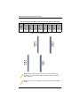
Table 3-1. Populating Eight Memory Slots for Interleaved Operation (Each Node)
CPU1
CPU2
# of
Channel Channel Channel Channel Channel Channel Channel Channel
DIMMs
A
B
C
D
E
F
G
H
A1
B1
C1
D1
E1
F1
G1
H1
X
X
X
X
X
X
X
X
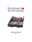
P1-DIMMH D1
P1-DIMMH C1
P1-DIMMH A1
P1-DIMMH B1
Figure 3-13. 8-slot DIMM Numbering
P2-DIMM F1
P2-DIMM E1
P2-DIMM G1
P2-DIMM H1
8
NOTE: Though multiple DIMM memory module types and speeds may be
supported, you need to use DIMM memory modules of the same speed and
type for each slot.
NOTE: An “X” in Table 3-1 indicates the memory slot is populated by a DIMM
module.
3-10
Chapter 3: Setup and Installation
NOTE: For an optimized memory bandwidth, it is recommended that you
populate the memory modules in sets of four (4) DIMMs for the CPU’s.
DIMM Installation
WARNING: Exercise extreme care when installing or removing DIMM modules
to prevent any possible damage.
Installing DIMM Memory Modules
1. Power down the blade module (see "Powering Down a Blade Unit" on page 3-1).
2. Remove the blade from the enclosure and the cover from the blade (see
"Removing/Replacing the Blade Cover" on page 3-2).
3. Remove the air shroud that covers the DIMM slots.
4. Insert each DIMM vertically into its slot, starting with slots 1A and 2A. Pay attention
to the notch along the bottom of the module to prevent inserting the DIMM
incorrectly (see Figure 3-14).
Figure 3-14. Installing a DIMM into a Memory Slot
To Install: Insert module vertically
and press down until it snaps into
place. Pay attention to the bottom
notch.
Notch
To Remove: Use your thumbs to
gently push each release tab
outward to free the DIMM from the
slot.
Side View
Release Tabs
Note: The notch should align with
the receptive key point on the slot.
Top View
5. Gently press down on the DIMM until it snaps into place in the slot. Repeat for all
modules (see Table 3-1 for installing DIMMs into the slots in the correct order).
6. Replace the air shroud and the blade cover and install the blade module back into
the enclosure.
7. Power up the blade unit (see "Powering Up a Blade Unit" on page 3-1).
3-11
SBI-7227R-T2 Blade Module User’s Manual
3-6
Hard Disk Drive Installation
Hard disk drives are installed in “carriers” which are hot-swappable and can be removed
or replaced without powering down the blade unit they reside in. A blade module needs
a hard disk drive with an operating system installed to operate.
WARNING: To maintain proper airflow, both hard drive bays must have drive
carriers inserted during operation whether or not a drive is installed in the carrier.
To remove a hard drive carrier, do the following:
Removing a Hard Drive Carrier
1. Locate the colored “Open” button at the bottom of the drive carrier and press it with
your thumb. This action releases the drive carrier from the drive bay.
2. Pull the release handle out about 45-degrees, then use it to pull the drive carrier out.
To Install a hard drive, use the following procedure:
Installing a Hard Drive
1. Remove a blank drive carrier from the blade (see removal procedure above).
2. Insert a drive into the carrier with the PCB side facing down and the connector end
toward the rear of the carrier.
3. Align the drive in the carrier so that the screw holes of both line up. Note that there
are holes in the carrier marked “SATA” to aid in correct installation.
4. Secure the drive to the carrier with six screws as shown in Figure 3-15.
5. Insert the drive carrier into its slot keeping the Open button at the bottom. When the
carrier reaches the rear of the bay the release handle will retract.
6. Push the handle in until you hear the carrier click into its locked position.
3-12
Chapter 3: Setup and Installation
Figure 3-15. Installing a Hard Drive in a Carrier
3-7
Installing the Operating System
An operating system (OS) must be installed on each blade module. Blades with
Microsoft Windows OS and blades with Linux OS can both occupy and operate within
the same blade enclosure. Refer to the SuperMicro web site for a complete list of
supported operating systems.
There are several methods of installing an OS to the blade modules.
3-13
SBI-7227R-T2 Blade Module User’s Manual
Installing with an External USB CD-ROM Drive
The most common method of installing the OS is with an external USB CD-ROM drive.
Take the following steps to install the OS to a blade module:
WARNING: Installing the OS from an external CD-ROM drive may take several
hours to complete.
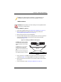
1. Connect an SUV cable (Serial port/USB port/Video port cable) to the KVM
connector on the front of the blade module. You will then need to attach a USB hub
to the USB port on this cable to provide multiple USB ports.
2. Connect the external CD-ROM drive, a USB keyboard and a mouse to the USB hub.
You will also need to connect a monitor to the video connector on the SUV cable.
Turn on the blade module.
3. Insert the CD containing the OS into the CD-ROM drive.
4. Follow the prompts to begin the installation.
Installing via PXE Boot
PXE (Preboot Execution Environment) is used to boot a computer over a network. To
install the OS via PXE, the following conditions must be met:
1. The PXE BOOT option in BIOS must be enabled.
2. A PXE server has been configured (this can be another blade in the system).
3. The PXE server must be connected over a network to the blade to be booted.
4. The blade has only non-partitioned/unformatted hard drives installed and no
bootable devices attached to it.
Once these conditions are met, make sure the PXE server is running. Then turn on the
blade on which you wish to boot and/or install the OS. The BIOS in the blade will look at
all bootable devices and finding none will connect to the PXE server to begin the boot/
install.
Installing via Virtual Media (Drive Redirection)
You can install the OS via Virtual Media through either the IPMIview (Java based client
utility), IPMItool or the Web-based Management Utility. With this method, the OS is
installed from an ISO image that resides on another system/blade.
Refer to the manuals on your SuperBlade CD-ROM for further details on the Virtual
Media (CD-ROM or Drive Redirection) sections of these two utility programs.
3-14
Chapter 3: Setup and Installation
3-8
Management Software
System management may be performed with either of three software packages:
IPMIview, IPMItool or a Web-based Management Utility. These are designed to provide
an administrator with a comprehensive set of functions and monitored data to keep tabs
on the system and perform management activities.
Refer to the manuals on our website for further details on the various functions provided
by these management programs.
3-9
Configuring and Setting up RAID
Each blade module that supports two or more hard drives may be used to create a RAID
array. The procedures for doing this vary depending upon the blade model chosen for
your SuperBlade system.
See Chapter 5 for details on how to configure and set up RAID on your blade module.
3-15
SBI-7227R-T2 Blade Module User’s Manual
Notes
3-16
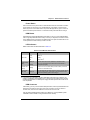
Chapter 4
Blade Module Features
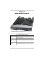
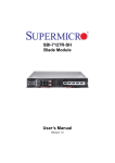
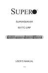
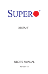
Figure 4-1. SBI-7227R-T2 Blade Unit Front View
This chapter describes the SBI-7227R-T2 blade unit. Installation and maintenance
should be performed by experienced technicians only.
See Figure 4-1 for a front view of the blade unit and Table 4-1 for its features.
Table 4-1. SBI-7227R-T2 Blade Unit Features
Feature
Description
Processors
Supports up to two 2011-pin (LGA2011 Socket R) Intel Xeon E5-2600
series processors per node
Memory
Supports up to 256 GB of RDIMM and 64 GB of UDIMM DDR3 1600/1333/
1066 MHz speed SDRAM in eight (8) 240-pin DIMM sockets per node
Storage
Up to two hot-plug 2.5" hot pluggable 2.5" enterprise SATA/SSD drives per
node
Ports
KVM ports (1) per node (two total)
Features
Each node has an onboard Integrated Matrox G200eW Graphics chip,
IPMI 2.0, ATA/100, Plug and Play, APM 1.2, DMI 2.3, PCI 2.2, ACPI 1.0/
2.0, SMBIOS 2.3, Real Time Clock and Watch Dog
4-1
SBI-7227R-T2 Blade Module User’s Manual
4-1
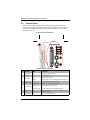
Control Panel
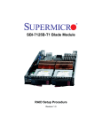
Each of the two nodes for the SBI-7227R-T2 blade has an identical control panel
(Figure 4-2) with power on/off button, a KVM connector, a KVM button and four LEDs on
both the top and bottom front of the unit. The numbers mentioned in Figure 4-2are
described in Table 4-2.
Figure 4-2. Blade Control Panel
7
3
4
5
6
1
2
Table 4-2. Blade Control Panel
Item Function
State
Description
1
Power Button
N/A
Turns blade module on and off
2
KVM Button
N/A
Initiates KVM function
3
Power LED
4
5
Green
Indicates power status “On”
Orange
Indicates power status “Off” (with power cables plugged in)
Blue
Indicates KVM being utilized on blade unit
Flashing Blue
Indicates UID activated on blade module
Flashing Green
Indicates network activity over LAN
KVM/UID LED
Network/IB LED
Flashing Orange Indicates network activity over InfiniBand module
6
System Fault
LED
7
KVM Connector N/A
Red
Indicates a memory error, overheat, VGA error or any error
that prevents booting
Connector for SUV/KVM cable
4-2
Chapter 4: Blade Module Features
Power Button
Each node has its own power button so that individual nodes for each blade unit within
the enclosure may be turned on or off independently of the others. Press the power
button (#1) to turn on the blade server. The power LED (#3) will turn green. To turn off,
press and hold the power button for >4 seconds and the power LED will turn orange.
KVM Button
KVM stands for Keyboard/Video/Mouse. With KVM, a user can control multiple blades
with a single keyboard/video/mouse setup. Connect your keyboard, mouse and monitor
to the USB and VGA connectors on the CMM module, then push the KVM button on the
control panel of the blade module you wish to access.
LED Indicators
Blade module LEDs are described below in Table 4-3.
Table 4-3. Blade Module LED Indicators
LED
State
Description
Green
Power On
Amber
Standby
Red
Power Failurea
Steady On
Indicates that KVM has been initialized on this blade module
Flashing
Serves as a UID indicator (the UID function is activated with a
management program)
Network LED
(Green)
Flashing
Flashes on and off to indicate traffic (Tx and Rx data) on the LAN
connection to this blade module.
System Fault
LED (Red)
Steady On
This LED illuminates red when a fatal error occurs. This may be the
result of a memory error, a VGA error or any other fatal error that
prevents the operating system from booting up.
Power LED
KVM/UID LED
(Blue)
a. In the event of a power failure, the N+1 Redundant Power Supply (if included in your
system's configuration) automatically turns on and picks up the system load to provide
uninterrupted operation. The failed power supply should be replaced with a new one as
soon as possible.
KVM Connector
Alternatively, you may connect a KVM cable (CBL-0218L, with a keyboard/video/mouse
attached) to the KVM connector (#7) of the node you wish to access. To switch to
another node, disconnect the cable then reconnect it to the new node.
See the Web-based Management Utility User’s Manual on your SuperBlade system
CD-ROM for further details on using the KVM function remotely.
4-3
SBI-7227R-T2 Blade Module User’s Manual
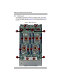
4-2
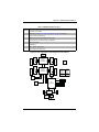
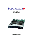
Mainboard
The mainboard of the SBI-7227R-T2 blade unit is a proprietary design, which is based
on the Intel C602 chipset. See Figure 4-4 for a block diagram of this chipset, Figure 4-3
for a view of the B9DRT mainboard and Figure 4-5 for an exploded view diagram of the
blade unit.
Figure 4-3. B9DRT Mainboard
5
5
4
6
4
6
9
8
1
2
2
2
1
2
2
2
1
1
2
2
7
7
3
3
4-4
Chapter 4: Blade Module Features
Table 4-4. B9DRT Mainboard Layout
Item
Description
1
LGA 2011 CPU Sockets
2
DIMM Slots (see Figure 3-5: "Memory Installation" on page 3-9 for details)
3
two 2.5" SATA Hard Drive Bays
4
InfiniBand Connectors (for InfiniBand or 10G card)
5
Gbx Connectors (for power and logic to backplane)
6
Intel C602 Chipset
7
KVM Module
8
JBT1 Left Node CMOS Clear
9
JKBT1 Right Node CMOS Clear
Figure 4-4. Intel C602 Chipset: Block Diagram (For Each Node)
DDR3 DIMM
DDR3 DIMM
G
CLOCK
CK420
B
A
DDR3 DIMM
CPU Rear
Socket 0
Processor
Sandybridge
D
DDR3 DIMM
DDR3 DIMM
SPI
CPU 1
PX3897
SMB:48
Vcore/Vsa
CPU2
PX3897
SMB:68
Vcore/Vsa
IR3541
SMB:54/ 2A
VDDQAB/CD
IR3541
SMB:5C/ 2E
VDDQEF/GH
x8
IB
DMI
SAS/SATA
LAN
I350
x4
USB-0
SSB
PATSBURG
USB-3/4/5
Powerville
SAS/SATA #1
SAS/SATA #0
CMM-USB
PANEL-USB
USB-12/13
BMC-USB
PCI
WPCM450
VGA BMC
VGA Front
CMM (Top)
CMM (Bot)
PHY
RTL8201
CMM Top & Bot
4-5
LPC
TPM HDR
DDR II
DDR3 DIMM
C
H
QPI
CPU Front
Socket 1
Processor
Sandybridge
F
QPI
E
DDR3 DIMM
DDR3 DIMM
VR12
5 PHASE
95W
SBI-7227R-T2 Blade Module User’s Manual
Jumpers
The jumpers present on the mainboard are used by the manufacturer only; there are no
jumpers used to configure the operation of the mainboard.
CMOS Clear
JBT1 and JKBT1 are each used to clear CMOS for each respective node on the
mainboard and will also clear any passwords. Each consists of two contact pads located
on the board underneath the chipset heatsinks.
Clearing CMOS
1. First power down the blade and remove it from the enclosure.
2. Remove the blade cover to access the mainboard (see Section : Removing/
Replacing the Blade Cover on page 3-2 for further details). Short the CMOS pads
with a metal object such as a small screwdriver.
3. Replace the cover, install the blade back into the enclosure and power it on.
4-6
Chapter 4: Blade Module Features
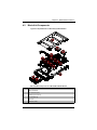
4-3
Blade Unit Components
Figure 4-5. Exploded View of a SBI-7227R-T2 Blade Module
5
6
6
3
4
3
3
4
4
3
3
4
3
1
2
2
Table 4-5. Main Components of a SBI-7227R-T2 Blade Module
Item
Description
1
Blade Unit/Module
2
2.5" Hard Drives (two)
3
DIMMs (system memory)
4
CPU Heatsinks (2)
5
Top Cover
6
Mezzanine Cards
4-7
SBI-7227R-T2 Blade Module User’s Manual
Memory Support
Each node of the SBI-7227R-T2 blade module supports up to 256 GB of RDIMM and 64
GB of UDIMM DDR3 1600/1333/1066 MHz speed SDRAM in eight (8) 240-pin DIMM
sockets. See Section 3-5: Memory Installation on page 3-9 for further details on
mainboard memory installation.
Hard Disk Drives
Each node of the SBI-7227R-T2 blade unit supports up to two 2.5" SATA hard disk
drives, which are mounted in drive “trays”. The drives can be hot-swapped and removed
or replaced without powering down the blade unit they reside in. The two drives for each
node can be used to set up a RAID array (RAID 0, 1, 5 and 10 Windows; RAID 0, 1 and
10 Linux) or JBOD. These drives use a yellow color for the Blade HDD active LED. See
Chapter 5: "RAID Setup Procedure" on page 5-1 for further details on RAID Setup.
WARNING: To maintain proper airflow, both hard drive bays must have drive
carriers inserted during operation whether or not a drive is installed in the tray.
4-8
Chapter 5
RAID Setup Procedure
Each SBI-7227R-T2 blade module supports up to three hard drives, which may be used
to create a RAID 0, 1, 5 and 10 (Windows) or RAID 0, 1 and 10 (Linux) array. For RAID
setup use the procedure below. This blade’s BIOS has a RAID utility available in its
setup.
5-1
RAID Configurations
With two or hard drives per blade, the following RAID configurations are supported:
•
RAID 0 (Data Striping): this writes data in parallel, interleaved (“striped”) sections on
two hard drives. Data transfer rate is doubled over using a single disk.
•
RAID1 (Data Mirroring): an identical data image from one drive is copied to another
drive. The second drive must be the same size or larger than the first drive.
•
Enhanced RAID 5 or RAID 10 (Data Mirroring): as RAID1 with data mirrored from
one or more disks to one or more disks of a second, larger size. You can couple the
disks from the source to create a virtual volume and use one or more disks of a
second, larger size to provide a single larger volume (or multiple larger volumes)
that serve as the mirroring drive or drives for the array.
5-2
Preparing for Setup
Before you begin the installation, verify the following:
1. The SBI-7227R-T2 blade module has two or more hard drives installed.
2. These drives must not have an OS installed and must be non-partitioned (formatted
is ok).
3. The installation procedure is done via KVM, so have a KVM cable (CBL-0218L)
connected to the KVM connector on the blade module with a keyboard, mouse and
monitor attached.
NOTE: You may also instead use IPMI or the Web-based Management utility to
access the blade.
5-1
SBI-7227R-T2 Blade Module User’s Manual
5-3
RAID Setup Procedure
This section provides instructions for configuring arrays and logical drives with the RAID
BIOS Configuration Utility.
It is recommended that you use drives with the same capacity when you create a
storage configurations. If you use drives with different capacities in one array, the
configuration utility limits each drive to the capacity of the smallest drive.
The number of physical drives in a specific array determines the possible RAID levels
that you can implement with the array.
Enabling SATA RAID in the BIOS
Before installing the Windows Operating System, you must change some settings in
BIOS. Boot up the system and hit the <Del> key to enter the BIOS Setup Utlility. After
the Setup Utility loads,
1. Use the arrow keys to move to the EXIT menu. Scroll down with the arrow keys to
the LOAD OPTIMAL DEFAULTS setting and press <ENTER>. Select OK to confirm, then
<ENTER> to load the default settings.
2. Use the arrow keys to move to the ADVANCED menu, then scroll down to SATA
CONFIGURATION. Once in this submenu, scroll down to SATA MODE and choose the
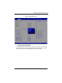
RAID MODE option (see Figure 5-1).
3. Hit the <ESC> key twice and scroll to the EXIT menu. Select SAVE CHANGES AND EXIT
and hit <ENTER>, then hit <ENTER> again to verify.
4. After exiting the BIOS Setup Utility, the system will reboot. When prompted during
the startup, press the <CTRL+A> key when prompted to run the Intel RAID Utility
program (see "Using the Intel RAID Utility" on page 5-3).
5-2
Chapter 5: RAID Setup Procedure
Figure 5-1. BIOS Setup Screen
Using the Intel RAID Utility
The Intel® RAID Utility program is where you can define the drives you want to include
in the RAID array and the mode and type of RAID. In the INTEL RAID UTILITY PROGRAM
screen you can create an array, add hotspares and configure your drives.
5-3
SBI-7227R-T2 Blade Module User’s Manual
Notes
5-4
Chapter 6
BIOS
6-1
Introduction
This chapter describes the BIOS for Intel SuperBlade modules. The Intel Blade modules
use a 128 MB SPI Flash EEPROM with AMI® BIOS each node™ that is stored in a flash
chip. This BIOS can be easily upgraded using a floppy disk-based program. Each node
in the SBI-7227R-T2 blade module has its own BIOS system.
NOTE: Due to periodic changes to the BIOS, some settings may have been
added or deleted and might not yet be recorded in this manual. Please refer to
the http://www.supermicro.com/products/SuperBlade/module/ web site for
further details on BIOS setup and the BIOS menus for your SuperBlade blade
module.
System BIOS
BIOS stands for Basic Input Output System. The 128 MB SPI Flash EEPROM with
AMI® BIOS each node BIOS flash chip stores the system parameters, types of disk
drives, video displays, in the CMOS. The CMOS memory requires very little electrical
power. When the blade unit is turned off, a backup battery provides power to the BIOS
flash chip, enabling it to retain system parameters. Each time the blade is powered on it
is configured with the values stored in the BIOS ROM by the system BIOS, which gains
control at boot up.
How To Change the Configuration Data
The CMOS information that determines the system parameters may be changed by
entering the BIOS Setup utility. This Setup utility can be accessed by pressing the
<DELETE> key at the appropriate time during system boot. (See "Starting the Setup
Utility" below.)
Starting the Setup Utility
Normally, the only visible POST (Power-On Self-Test) routine is the memory test. As the
memory is being tested, press the <DELETE> key to enter the main menu of the BIOS
Setup utility. From the main menu, you can access the other setup screens, such as the
Security and Power menus.
WARNING: To prevent possible boot failure, do not shut down or reset the
system while updating the BIOS.
6-1
SBI-7227R-T2 Blade Module User’s Manual
6-2
BIOS Updates
It may be necessary to update the BIOS used in the blade modules on occasion.
However, it is recommended that you not update BIOS if you are not experiencing
problems with a blade module.
Updated BIOS files are located on our web site(www.supermicro.com/products/
superblade/). Please check the current BIOS revision and make sure it is newer than
your current BIOS before downloading.
There are several methods you may use to upgrade (flash) your BIOS. After
downloading the appropriate BIOS file (in a zip file format), follow one of the methods
described below to flash the new BIOS.
Flashing BIOS
Use the procedures below to “Flash” your BIOS with a new update using the KVM
dongle, USB ports on the CMM module or by use of a Floppy disk.
Flashing a BIOS using the KVM Dongle:
For this method, you must use a KVM “dongle” cable (CBL-0218L, included with the
system).
1. Copy the contents of the zip file to a bootable USB pen drive.
2. Connect the KVM dongle (CBL-0218L) to the KVM connector at the front of the
blade you will be flashing the BIOS to.
3. Connect your bootable USB pen drive to one of the two USB slots on the KVM
dongle.
4. Boot to the USB pen drive and go to the directory where you saved the contents of
the zip file.
5. Type flash filename.rom (replace filename.rom by the actual ROM file name).
Flashing a BIOS using the USB Ports on the CMM:
1. Copy the contents of the zip file to a bootable USB pen drive.
2. Connect your bootable USB pen drive to one of the two USB slots on the CMM
(located on the back side of the enclosure).
3. Boot to the USB pen drive and go to the directory where you saved the contents of
the zip file.
4. Type flash filename.rom (replace filename.rom by the actual ROM file name).
Flashing a BIOS using a Floppy Image File
This method must be performed remotely.
1. Copy the image file from the zip file to your desktop.
2. Use the web browser or IPMIView to access your CMM remotely using its IP
Address.
6-2
Chapter 6: BIOS
3. Go to the VIRTUAL MEDIA menu and select FLOPPY IMAGE UPLOAD.
4. BROWSE or OPEN to locate the *.img file on your desktop and select it.
5. Press the UPLOAD button and wait a few seconds for the image to upload to the
CMM.
6. Once the upload finishes, turn on the blade module and press <DEL> to enter the
BIOS setup utility.
7. In the BOOT MENU, bring USB LS120: PEPPCMM VIRTUAL DISC 1 to the top of
the boot priority list.
8. Exit while saving the changes. The blade module will boot to the virtual media
(floppy image) A:\>.
9. Type flash filename.rom.
NOTE: Replace filename.rom by the actual ROM file name (such as
B8DTE142.rom for example) in the command.
6-3
Running Setup
NOTE: Default settings are in bold text unless otherwise noted.
The BIOS setup options described in this section are selected by choosing the
appropriate text from the MAIN BIOS SETUP screen. All displayed text is described in this
section, although the screen display is often all you need to understand how to set the
options.
When you first power on the computer, the BIOS is immediately activated.
While the BIOS is in control, the Setup program can be activated in one of two ways:
1. By pressing <DELETE> immediately after turning the system on, or
2. When the message Press the <Delete> key to enter Setup appears briefly at the
bottom of the screen during the POST, press the <DELETE> key to activate the main
SETUP menu:
6-3
SBI-7227R-T2 Blade Module User’s Manual
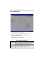
6-4
Main BIOS Setup
Figure 6-1. BIOS Setup Screen
All Main Setup options are described in this section.
Use the UP/DOWN arrow keys to move among the different settings in each menu. Use
the LEFT/RIGHT arrow keys to change the options for each setting.
Press the <ESC> key to exit the CMOS SETUP menu. The next section describes in
detail how to navigate through the menus.
Items that use sub-menus are indicated with the icon. With the item highlighted,
press the <ENTER> key to access the submenu.
Menu options found in the MAIN BIOS SETUP menu are described in Table 6-1.
Table 6-1. Main BIOS Setup Menu Options
Menu Option
Description
System Date
Using the arrow keys, highlight the month, day and year fields, and enter the
correct data for the system date. Press the <Enter> key to save the data.
System Time
To set the system date and time, key in the correct information in the appropriate
fields. Then press the <Enter> key to save the data.
BIOS Information
BIOS static display information including the motherboard number, SMC version,
SMC Build Date and Total Memory is also shown on the screen.
6-4
Chapter 6: BIOS
6-5
Advanced Setup
Choose Advanced from the BIOS Setup Utility main menu with the arrow keys to
display the ADVANCED SETUP menu. The items with a triangle beside them are
sub-menus that can be accessed by highlighting the item and pressing <ENTER>.
Options for PIR settings are displayed by highlighting the setting option using the arrow
keys and pressing <ENTER>.
Table 6-2 describes all sub-menus found in the ADVANCED SETUP menu.
Table 6-2. Advanced Setup Menu Options
Sub-menu
Description
Boot Feature
See Table 6-3 for a description of BIOS setup menu options in this sub-menu.
CPU Configuration
See Table 6-4 for a description of BIOS setup menu options in this sub-menu.
Chipset
Configuration
See Table 6-5 for a description of BIOS setup menu options in this sub-menu.
SATA Configuration See Table 6-6 for a description of BIOS setup menu options in this sub-menu.
PCIe/PII/PnP
Configuration
See Table 6-7 for a description of BIOS setup menu options in this sub-menu.
SuperIO
Configuration
(WPCM450)
See Table 6-8 for a description of BIOS setup menu options in this sub-menu.
Serial Port Console
See Table 6-9 for a description of BIOS setup menu options in this sub-menu.
Redirection
ACPI Configuration See Table 6-10 for a description of BIOS setup menu options in this sub-menu.
ME Subsystem
See Table 6-11 for a description of BIOS setup menu options in this sub-menu.
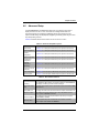
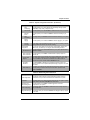
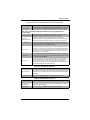
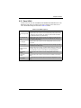
Table 6-3. Boot Feature Submenu
Menu Option
Description
Quiet Boot
When Disabled the BIOS displays normal POST messages. When Enabled the
BIOS displays an OEM Logo instead of POST messages.
AddOn ROM Display
Mode
This setting sets the display mode for Option ROM. Options include Force BIOS
or Keep Current.
Bootup NUM-Lock
This setting selects the Power-On state for Numlock. Options include On or Off.
Wait for ‘F1’ If Error
When enabled, the system will wait for the F1 key to be pressed if an error
occurs. Options are Enabled or Disabled.
Interrupt 19 Capture
When enabled this setting allows option ROMs to trap Interrup 19. Options
include Enabled or Disabled.
Watch Dog Timer
This setting allows the system to restart when it is not active more than 5
minutes. Option include Enabled and Disabled.
6-5
SBI-7227R-T2 Blade Module User’s Manual
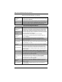
Table 6-3. Boot Feature Submenu (Continued)
Menu Option
Description
Power Button
Function
This setting specifies the power button’s function when pressed. Option include 4
Seconds Override or Instant Off.
This setting specifies what the system will do when power is restored after an AC
Restore on AC Power power loss to the system. Options include Stay Off (system power remains off
Loss
after power loss), Power-On (system power turns on after power loss) or Last
State (allows the system to resume its last state before the power loss).
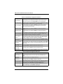
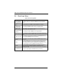
Table 6-4. CPU Configuration Submenu
Menu Option
Description
Socket 1 CPU
Information
These submenus, when selected, shows information on the Socket 1/Socket 2
processors and other information including CPU Signature, Microcode Patch,
CPU Stepping, Max CPU Speed, Min CPU Speed, Processor Cores, Intel HT
Technology, Intel VT-x Technology, L1 Data Cache, L1 Code Cache, L2 Cache
and L3 Cache. Additionally, the CPU Configuration submenu shows information
about the CPU Speed and 64-bit support.
The information shown is only readable and cannot be changed.
Socket 2 CPU
Information
Clock Spread
Spectrum
This setting enables or disables spread spectrum modulation. Options are
Enabled and Disabled.
Hyper-threading
This setting is Enabled for Windows XP and Linux (OS optimized for
Hyper-threading technology), and Disabled for other OSes (any OS not
optimized for Hyper-threading techology). When Disabled, only one thread per
enabled core is enabled.
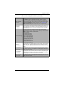
Active Processor
Cores
This setting selects the number of cores to enable in each processor package.
Options include All, 1, 2, 4 and 6.
Limit CPUID
Maximum
This setting is disabled for Windows XP. Options include Enabled or Disabled.
Execute Disable Bit
XD can prevent certain classes of malicious buffer overflow attacks when
combined with a supporting OS such as Windows Server 2003 SP1, Windows
XP SP2, SuSE Linux 9.2 or RedHat Enterprise 3 Update 3. Options include
Enabled or Disabled.
Hardware Prefetcher
If set to Enabled, the hardware prefetcher will prefetch streams of data and
instructions from the main memory to the L2 cache in the forward or backward
manner to improve CPU performance. Options are Enabled and Disabled.
For UP platforms leave it enabled. for DP/MP servers, this setting may be used
to tune performance to the specific application.
Adjacent Cache Line
Prefetch
The CPU fetches the cache line for 64-bytes if this option is set to Disabled. The
CPU fetches both cache lines for 128-bytes as comprised if Enabled.
For UP platforms leave it enabled. for DP/MP servers, this setting may be used
to tune performance to the specific application.
DCU Streamer
Prefetcher
For UP platforms, leave this option Enabled. For DP/MP servers, this option
may be used to tune performance to the specific application. Options are
Enabled or Disabled.
DCU IP Prefetcher
This setting Enables or Disables prefetch of the next L1 line based upon
sequential load history.
6-6
Chapter 6: BIOS
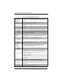
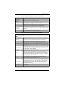
Table 6-4. CPU Configuration Submenu (Continued)
Menu Option
Description
Intel® Virtualization
Technology
Select Enabled to use this Virtualization Technology feature to allow one
platform to run multiple operating systems and applications in independent
partitions, creating multiple “virtual” systems in one physical computer system.
The options are Enabled and Disabled. Please refer to the Intel website for
further detailed information.
NOTE: A full reset of the system is required when you change this setting.
CPU Power
Management
Configuration
Power management options and information is displayed on this submenu. In
addition to the options in this submenu, information is displayed for Factory Long
Duration Power Limit, Factory Long Duration Maintained and Recommended
Short Duration Power.
This option enables power managment features. Options include Disable,
Energy Efficient and Custom. Selecting “Custom” allows you to either Enable or
Disable the following features and their defaults:
• EIST (Enabled)
• Turbot Mode (Enabled)
• C1E Support (Enabled)
• CPU C3 Report (Disabled)
Power Technology
• CPU C6 Report (Enabled)
• CPU C7 Report (Enabled)
• Package C-state Limit (C6)
• Energy Performance
• Long Duration Power Limit
• Long Duration Maintained
Energy
Performance
This option allows you to optimize between power and energy savings. Windows
2008 and later OSes overides this value according to its power plan. Options
include Performance, Balanced Performance, Balanced Energy and Energy
Efficient.
Long Duration
Power Limit
This option allows you to set the long duration power limit in Watts. To set the
value, enter a number from your keyboard in the field highlighted. To reset the
number, enter a new number.
Long Duration
Maintained
This option allows you to set the time window for which the long duration power
limit is maintained. To set the time value, enter a number from your keyboard in
the field highlighted. To reset the number, enter a new number.
Short Duration
Power Limit
This option allows you to set the short duration power limit in Watts. To set the
value, enter a number from your keyboard in the field highlighted. To reset the
number, enter a new number.
6-7
SBI-7227R-T2 Blade Module User’s Manual
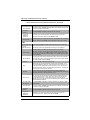
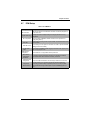
Table 6-5. Chipset Configuration Sub-menu
Menu Option
Description
North Bridge
Configuration
This sub-menu configures North Bridge features and shows configuration
information.
IOH
Configuration
This submenu configures Intel VT-d and Intel I/OAT in your system and
configures IOU PCIe port bifurcation controls.
Intel VT-d
This setting allows you to Enable or Disable Intel Virtualization Technology for in
your system.
Intel I/OAT
This setting allows you to Enable or Disable Intel I/O Acceleration Technology in
your system.
DCA Support
This setting allows you to Enable or Disable DCA support in your system.
IOH 0/1
PCIe Port
Bifurcation
Controls
Both IOH 0 and IOH 1 PCIe port bifurcation controls are available to set IOU Link
Speed and PCIe Port settings. Options include Gen 1, Gen 2 or Gen 3 link speed
settings or various port PCIe settings for x4x4, x8, x4x4x4, x4x4x8, x8x4x4, x8x8
or x16 (default depends upon setting).
QPI
Configuration
This submenu statically displays Current QPI Link Speed and Current QPI Link
Freq as well as providing options for Isoc, QPI Link Speed Mode and QPI Link
Frequency Select.
Isoc
This setting allows you to Enable or Disable Isoc in your system.
QPI Link
Speed Mode
This setting allows you to select QPI Link Speed as being either Fast or Slow
mode.
QPI Link
Frequency
Select
This setting allows you to select the QPI link frequency. Options include Auto,
6.4 GT/s, 7.2 GT/s or 8.0 GT/s.
DIMM
Configuration
DIMM
Information
This submenu displays static Memory Configuration information (Current
Memory Mode, Current Memory Speed, Mirroring and Sparing), DIMM
Information and other option settings.
DIMM presence and size information is shown in this submenu when selected.
This setting sets the system memory mode. Options include the following:
• Independent (default) – All DIMMs are available to the operating system.
• Mirroring – The mainboard maintains two identical copies of all data in
memory for redundancy.
Memory Mode
• Lock Step – The mainboard uses two areas of memory to run the same set
of operations in parallel.
• Sparing – A preset threshold of correctable errors is used to trigger fail-over.
The spare memory is put online and used as active memory in place of the
failed memory.
DRAM RAPL
Mode
This setting allows you to select DRAM RAPL Mode for your system. Options
include Disabled, DRAM RAPL Mode0 and DRAM RAPL MODE1.
DDR Speed
This setting allows you to force DDR speed for your system. Options include
Auto, Force DDR3 800, Force DDR 1066, Force DDR 1333, Force DDR 1600
and Force SPD.
Channel
Interleaving
This setting allows you to select different channel interleaving settings. Options
include Auto, 1 Way, 2 Way, 3 Way and 4 Way.
6-8
Chapter 6: BIOS
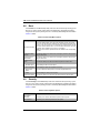
Table 6-5. Chipset Configuration Sub-menu (Continued)
Menu Option
Description
Rank
Interleaving
This setting allows you to select different rank interleaving settings. Options
include Auto, 1 Way, 2 Way, 4 Way and 8 Way.
Patrol Scrub
This setting allows you to either Enable or Disable Patrol Scrub for your system.
Demand
Scrub
This setting allows you to Enable or Disable the Demand Scrubbing in your
system.
Data
Scrambling
This setting allows you to Enable or Disable the Data Scrambling in your system.
Device
Tagging
This setting allows you to Enable or Disable the Device Tagging in your system.
Thermal
Throttling
For this setting, selecting Disabled sets Open Loop Thermal Throttling, whereas
selecting CLTT sets Closed Loop Thermal Throttling.
South Bridge
Configuration
All USB Devices
This sub-menu static displays PCH Information (chipset Name, Stepping and
USB Devices), and allows you to configure other South Bridge features.
This setting allows you to enable USB devices in your system. Options include
Enabled or Disabled.
EHCI Controller 1/ This setting allows you to Enable or Disabled USB 2.0 (EHCI) support for
EHCI Controller 2 Controller 1/2.
Legacy USB
Support
This setting allows you to enable the use of Legacy USB devices. If this option is
set to Auto, legacy USB support will be automatically enabled if a legacy USB
device is installed on the mainboard, and disabled if no USB devices are
connected. The options include Disabled, Enabled and Auto.
Port 60/64
Emulation
This setting Enables or Disables I/O port 60h/64h emulation support. This
should be enabled for the complete USB keyboard legacy support for non-USB
aware OSes.
EHCI Hand-off
This setting is a workaround for OSes without EHCI hand-off support. The EHCI
ownership change should be claimed by the EHCI driver. Options include
Enabled or Disabled.
Table 6-6. SATA Configuration Sub-menu
Menu Option
Description
SATA Configuration
This submenu contains settings for SATA configuration options as well as
information at the top on what hard disk drives are installed on the system.
SATA Mode
This setting allows you to specify the SATA mode used for your system. Options
include Disabled, IDE Mode, AHCI Mode and RAID Mode.
Aggressive Link
Power Management
This setting allows you to Enable or Disable Aggressive Link Power
Management for your system.
Port 0~5 Hog Plug
These settings allow you to Enable or Disable SATA Port Hot Plug support for
each port specified.
Staggered Startup (5)
These settings allow you to Enable or Disable AHCI Staggered Spin-up support
for each drive.
6-9
SBI-7227R-T2 Blade Module User’s Manual
Table 6-7. PCIe/PCI/PnP Configuration Sub-menu
Menu Option
Description
PCI ROM Priority
Use this setting in case of multiple Option ROMs to specify what PCI Option
ROM to launch. Options include Legacy ROM and EFI Compatible ROM.
PCI Latency Timer
This sets the value to programmed into the PCI Latency Timer Register. Options
include 32, 64, 96, 128, 160, 192, 224 an 248.PCI Bus Clocks.
Above 4G Decoding
This setting allows you to Enables or Disables decoding of 64-bit capable
devices in the Above 4G Address Space. This setting is only usable if your
system supports 64-bit PCI decoding.
PERR# Generation
This setting allows you to Enable or Disable the PCI device to generate a
PERR#.
SERR# Generation
This setting allows you to Enable or Disable the PCI device to generate a
SERR#.
Maximum Payload
Use this setting to set the maximum payload of the PCI Express device or allow
the system BIOS to select the value. Options include Auto, 128 Bytes, 256
Bytes, 512 Bytes, 1024 Bytes, 2048 Bytes or 4096 Bytes.
Maximum Read
Request
Use this setting to set the maximum read request size of the PCI Express device
or allow the system BIOS to select the value. Options include Auto, 128 Bytes,
256 Bytes, 512 Bytes, 1024 Bytes, 2048 Bytes or 4096 Bytes.
ASPM Support
This sets the ASPM Level for your system. Options include Disabled (disables
ASPM), Auto (lets BIOS auto configure) or Force L0s (force all links to L0s state).
This setting allows you to select the onboard LAN option ROM to be either PXE
Onboard LAN Option
or iSCSI. Note: If iSCSI is selected, LAN1 Option ROM select will cover all other
ROM Select
Oboard LANs.
Load Onboard LAN 1
This setting Enables or Disables onboard option ROM for LAN1.
Option ROM
Load Onboard LAN 2
This setting Enables or Disables onboard option ROM for LAN2.
Option ROM
Network Stack
This setting allows you to Enable or Disable the network stack (Pxe and UEFI).
Table 6-8. SuperIO Configuration Sub-menu
Menu Option
Description
Super IO Chip
This static display shows the name of the Super IO chip installed for your
system.
Serial Port 1
Configuration
This submenu allows you to configure Serial Port 1.
Serial Port
This setting allows you to Enable or Disable the Serial Port.
Change Settings
Use this setting to select an optimal setting for the Super IO device to use for the
Serial Port. Options include Auto, IO=3F8h/IRQ=4, IO=3F8h/IRQ=3~12,
IO=2F8h/IRQ=3~12, IO=3E8h/IRQ=3~12 and IO=2E8h/IRQ=3~12
Serial Port Mode
This setting allows you to set the Serial Port Mode to either Serial Over LAN
(SOL) or COM. Options include Normal or High Speed.
6-10
Chapter 6: BIOS
Table 6-8. SuperIO Configuration Sub-menu (Continued)
Menu Option
Description
Serial Port 2
Configuration
submenu
This submenu allows you to configure Serial Port 2.
Serial Port
This setting allows you to Enable or Disable the Serial Port.
Change Settings
Use this setting to select an optimal setting for the Super IO device to use for the
Serial Port. Options include Auto, IO=3F8h/IRQ=4, IO=3F8h/IRQ=3~12,
IO=2F8h/IRQ=3~12, IO=3E8h/IRQ=3~12 and IO=2E8h/IRQ=3~12
Serial Port
Attribute
This setting allows you to set either Serial over LAN (SOL) or COM for the serial
port attribute.
Serial Port Mode
This setting allows you to set the Serial Port Mode to either Serial Over LAN
(SOL) or COM. Options include Normal or High Speed.
Table 6-9. Serial Port Console Redirection Sub-menu
Menu Option
Description
COM1
Console Redirection
Use this setting to Enable or Disable Console Redirection for the COM1 port.
Console
Redirection Settings
This submenu contains Console Redirection settings for the COM1 port.
Terminal Type
This setting allows you to select the Terminal Type to use for Console
Redirection emulation. Options include ANSI (extended ASCII character set),
VT100 (ASCII character set), VT100+ (extends VT100 to support color, function
keys, etc.) and VT-UTF8 (uses UTF8 encoding to map Unicode characters onto
one or more bytes).
Bits per Second
This setting selects the serial port transmission speed, which must be matched
on the other side. Long or noisy lines may require lower speeds. Options include
9600, 19200, 38400, 57600 and 115200.
Data Bits
This sets the number of data bits as either 7 or 8.
Parity
A parity bit can be sent with the data bits to detect some transmission errors.
Options include None (no parity bit), Even (parity bit is 0 if the number of 1’s in
the data bits is even), Odd (parity bit is 0 if the number of 1’s in the data bits is
odd), Mark (parity bit is always 1) or Space (parity bit is always 0. The Mark and
Space Parity do not allow for error detection.
Stop Bits
Stop bits indicate the end of a serial data packet (a start bit indicates the
beginning). The standard setting is 1 stop bit. Communications with slow devices
may require more than 1 stop bit. Options are 1 or 2.
Flow Control
Flow control can prevent data loss from buffer overflow. When sending data, if
the receiving buffers are full, a ‘stop’ signal can be sent to stop the data flow.
Once the buffers are empty, a ‘start’ signal can be sent to re-start the flow.
Hardware flow control uses two wires to send start/stop signals. Options include
None and Hardware RTS/CTS.
VT-UTF8 Combo
Key Support
This setting Enables or Disables VT-UTF8 Combination Key support for ANSI/
VT100 terminals.
6-11
SBI-7227R-T2 Blade Module User’s Manual
Table 6-9. Serial Port Console Redirection Sub-menu (Continued)
Menu Option
Description
Recorder Mode
This setting Enables or Disables Recorder Mode. When enabled only text will be
sent. This is to capture Terminal data.
Resolution
100x31
This setting Enables or Disables extended terminal resolution.
Legacy OS
Redirection
Resolution
This allows you to set for legacy OSes the number of rows and columns
supported for redirection. Options include 80x24 or 80x25.
Putty KeyPad
This setting allows you to select the funtion key and KeyPad to use on the Putty
keyboard. Options include VT100, LINUX, XTERMR6, SCO, ESCN or VT400.
COM2
Console Redirection
Use this setting to Enable or Disable Console Redirection for the COM2 port.
Console
Redirection Settings
This submenu contains Console Redirection settings for the COM2 port.
Terminal Type
This setting allows you to select the Terminal Type to use for Console
Redirection emulation. Options include ANSI (extended ASCII character set),
VT100 (ASCII character set), VT100+ (extends VT100 to support color, function
keys, etc.) and VT-UTF8 (uses UTF8 encoding to map Unicode characters onto
one or more bytes).
Bits per Second
This setting selects the serial port transmission speed, which must be matched
on the other side. Long or noisy lines may require lower speeds. Options include
9600, 19200, 38400, 57600 and 115200.
Data Bits
This sets the number of data bits as either 7 or 8.
Parity
A parity bit can be sent with the data bits to detect some transmission errors.
Options include None (no parity bit), Even (parity bit is 0 if the number of 1’s in
the data bits is even), Odd (parity bit is 0 if the number of 1’s in the data bits is
odd), Mark (parity bit is always 1) or Space (parity bit is always 0. The Mark and
Space Parity do not allow for error detection.
Stop Bits
Stop bits indicate the end of a serial data packet (a start bit indicates the
beginning). The standard setting is 1 stop bit. Communications with slow devices
may require more than 1 stop bit. Options are 1 or 2.
Flow Control
Flow control can prevent data loss from buffer overflow. When sending data, if
the receiving buffers are full, a ‘stop’ signal can be sent to stop the data flow.
Once the buffers are empty, a ‘start’ signal can be sent to re-start the flow.
Hardware flow control uses two wires to send start/stop signals. Options include
None and Hardware RTS/CTS.
VT-UTF8 Combo
Key Support
This setting Enables or Disables VT-UTF8 Combination Key support for ANSI/
VT100 terminals.
Recorder Mode
This setting Enables or Disables Recorder Mode. When enabled only text will be
sent. This is to capture Terminal data.
Resolution
100x31
This setting Enables or Disables extended terminal resolution.
Legacy OS
Redirection
Resolution
This allows you to set for legacy OSes the number of rows and columns
supported for redirection. Options include 80x24 or 80x25.
6-12
Chapter 6: BIOS
Table 6-9. Serial Port Console Redirection Sub-menu (Continued)
Menu Option
Putty KeyPad
Description
This setting allows you to select the funtion key and KeyPad to use on the Putty
keyboard. Options include VT100, LINUX, XTERMR6, SCO, ESCN or VT400.
Serial Port for Out-of-Band Management/Windows Emergency Management
Services (EMS)
Console Redirection
Use this setting to Enable or Disable Console Redirection for Out-of-Band
Management/Windows Emergency Management Services (EMS).
Console
Redirection Settings
This submenu contains Console Redirection settings for Out-of-Band
Management/Windows Emergency Management Services (EMS). Static display
information for Data Bits, Parity and Stop Bits is also shown in this submenu.
Out-of-Band Mgmt
Port
Microsoft Windows Emergency Managment Services (EMS) allows for remote
managment of a Windows Server OS through a serial port. This setting allows
you to specify which port to use (COM1 or COM2).
Terminal Type
VT-UTF8 is the preferred terminal type for out-of-band management. The next
best choice is VT100+ and then VT100. Options include ANSI (extended ASCII
character set), VT100 (ASCII character set), VT100+ (extends VT100 to support
color, function keys, etc.) and VT-UTF8 (uses UTF8 encoding to map Unicode
characters onto one or more bytes).
Bits per Second
This setting selects the serial port transmission speed, which must be matched
on the other side. Long or noisy lines may require lower speeds. Options include
9600, 19200, 57600 and 115200.
Flow Control
Flow control can prevent data loss from buffer overflow. When sending data, if
the receiving buffers are full, a ‘stop’ signal can be sent to stop the data flow.
Once the buffers are empty, a ‘start’ signal can be sent to re-start the flow.
Hardware flow control uses two wires to send start/stop signals. Options include
None, Hardware RTS/CTS and Software Xon/Xoff.
Table 6-10. ACPI Settings Sub-menu
Menu Option
Description
ACPI Sleep State
This setting selects the highest ACPI sleep state the system will enter when the
SUSPEND button is pressed. Options include Suspend Disabled and S1 (CPU
Stop Clock).
High Precision Timer
Use this setting to Enable or Disable the High Precision Event Timer.
Table 6-11. ME Subsystem Sub-menu
Menu Option
Description
Intel ME Subsystem
Configuration
This submenu displays static information for the ME BIOS Interface Version and
the ME Version for your system.
ME Subsystem
This setting allows you to Enable or Disable ME Subsystem help.
6-13
SBI-7227R-T2 Blade Module User’s Manual
6-6
Event Logs Setup
Table 6-12. Event Logs Menu
Menu Option
Description
Change SMBIOS
Event Log Settings
This submenu allows you to change the SMBIOS Event Log configuration
settings.
SMBIOS Event
Log
This setting allows you to Enable or Disable SMBIOS Event Logging.
Runtime Error
Logging Support
Use this setting to Enable or Disable runtime error logging support.
Memory Corr.
Error Threshold
Use this setting to enter the memory correctable error threshold value of
between 1 and 15. The default value is 10.
PCI Error Logging
Use this setting to Enable or Disable PCI error logging support.
Support
Erase Event Log
Use this setting for erasing the SMBIOS Event Log. Erasing is done prior to any
logging activation during reset. Options are No, Yes Next Reset and Yes Every
Reset.
When Log is Full
Use this setting to choose options for reactions to a full SMBIOS Event Log.
Options include Do Nothing and Erase Immediately.
Log System Boot
Event
Use this setting to choose the option to Enable or Disable logging of system
boot events.
MECI
This setting (Multiple Event Count Increment) is used to select the number of
occurrences of a duplicate event that must pass before the multiple-event
counter associated with the log entry is updated. This is specified as a numeric
value in the range of 1 to 255. The default for this setting is set to 1.
METW
This setting (Multiple Event Time Window) is used to select the number of
minutes which must pass between duplicate log entries that utilize a
multiple-event counter. The value ranges from 0 to 99 minutes. The default for
this setting is set to 60.
View SMBIOS Event
Log
Selecting this option displays the SMIBIOS Event Log for viewing.
6-14
Chapter 6: BIOS
6-7
IPMI Setup
Table 6-13. IPMI Menu
Menu Option
Description
IPMI Information
IPMI Firmware Revision and IPMI Status information are statically displayed at
the top of this menu.
System Event Log
Selecting this submenu displays settings for changing the SEL Event Log
configuration.
SEL Components
Change this setting to Enable or Disable all features of the System Event
Logging during boot-up.
Erase SEL
Use this setting for erasing the SEL. Options are No, Yes On Next Reset and Yes
On Every Reset.
When SEL is Full
Use this setting to choose options for reactions to a full SEL. Options include Do
Nothing and Erase Immediately.
Log EFI Status
Codes
Use this setting to Enable or Disable logging of EFI status codes, log only error
codes or only progress codes
BMC Network
Configuration
BMC Network
Configuration
Information
Use this submenu to configure BMC network parameters.
The submenu contains static display information for the Station IP Address,
Subnet Mask, Station MAC Address and Gateway IP Address.
Update IPMI LAN
Specify Yes or No for the BIOS to use this setting for IPMI in the next boot-up.
Configuration
Configuration
Address Source
This setting allows you to configure LAN channel parameters Statically or
Dynamically (by BIOS or BMC). Unspecified option will not modify any BMC
network parameters during the BIOS phase. Options are DHCP (dynamic) or
Static.
6-15
SBI-7227R-T2 Blade Module User’s Manual
6-8
Boot
Choose Boot from the BIOS Setup Utility main menu with the arrow keys to bring up the
BOOT SETUP menu. Security setting options are displayed by highlighting the setting
using the arrow keys and pressing <ENTER>. All Security BIOS settings are described in
Table 6-14 below.
Table 6-14. Boot Setup Menu Options
Menu Option
Description
These menu settings allow you to specify the sequence of priority for the boot
device (such as hard disk drives, USB devices, CD-ROM drives, Network drives
and so on). The menu options are for 1st Boot Device, 2nd Boot Device and 3rd
Boot Device Priorities Boot device, 4th Boot Device and so on. Each numbered boot device can be set
to a specific device installed in your system or to Disabled.
NOTE: A device enclosed in parenthesis has been disabled in the corresponding
type menu.
USB Device BBS
Priorities
This submenu allows you to set the order of the legacy devices in this group for
setting the boot order.
Network Device
BBS Priorities
This submenu allows you to set the order of the legacy devices in this group for
setting the boot order.
Add New Boot
Option
This submenu allows you to add a new EFI boot option to the boot order.
Add Boot Option
Use this setting to add a new boot option.
Select Filesystem Use this setting to select one file system from the list.
Path for Boot
Option
Enter here a path to the boot option in the format fs0:\path\filename.efi
Create
Select this setting to create your boot option.
Delete Boot Option This submenu allows you to remove an EFI boot option form the boot order.
6-9
Security
Choose Security from the BIOS Setup main menu with the arrow keys to bring up the
SECURITY SETUP menu. Security setting options are displayed by highlighting the setting
using the arrow keys and pressing <ENTER>. All Security BIOS settings are described in
Table 6-15 below.
Table 6-15. Security Menu Options
Menu Option
Description
Administrator
Password
This allows you to create an administrator password for the system.
User Password
This allows you to create user password for the system.
6-16
Chapter 6: BIOS
6-10 Save & Exit
Choose SAVE & EXIT from the 128 MB SPI Flash EEPROM with AMI® BIOS each node
BIOS Setup Utility main menu with the arrow keys to display the SAVE & EXIT SETUP
menu. All Exit BIOS settings are described in Table 6-16 below.
Table 6-16. Exit Menu Options
Menu Option
Description
Highlight this item and hit <ENTER> to exit the BIOS Setup utility without saving
Discard Changes and
any changes you may have made. Any changes you have made to the BIOS
Exit
Setup will not take effect upon system bootup.
Save Changes and
Reset
Highlight this item and hit <ENTER> to save any changes you made and to exit
the BIOS Setup utility. The system will reboot and implement the changes you
have made to the BIOS Setup.
Save Changes
Highlight this item and hit <ENTER> to save changes done so far to any of the
setup options.
Discard Changes
Highlight this item and hit <ENTER> to discard (cancel) any changes you made.
You will remain in the Setup utility.
Restore Optimized
Defaults
Highlight this item and hit <ENTER> to load the default settings for all items in the
BIOS Setup. These are the safest settings to use and are designed for maximum
system performance, but may not work best for all computer applications.
Save as Users
Defaults
Highlight this item and hit <ENTER> to save changes done so far as user
defaults.
Restore User
Defaults
Highlight this item and hit <ENTER> to restore the user defaults to all the setup
options.
Boot Override
For each boot device you have the option of saving the configuration for it and
exiting.
6-17
SBI-7227R-T2 Blade Module User’s Manual
Notes
6-18
Disclaimer
The products sold by Supermicro are not intended for and will not be used in life support
systems, medical equipment, nuclear facilities or systems, aircraft, aircraft devices,
aircraft/emergency communication devices or other critical systems whose failure to
perform be reasonably expected to result in significant injury or loss of life or
catastrophic property damage. Accordingly, Supermicro disclaims any and all liability,
and should buyer use or sell such products for use in such ultra-hazardous applications,
it does so entirely at its own risk. Furthermore, buyer agrees to fully indemnify, defend
and hold Supermicro harmless for and against any and all claims, demands, actions,
litigation, and proceedings of any kind arising out of or related to such ultra-hazardous
use or sale.
0-1
SBI-7227R-T2 Blade Module User’s Manual
0-2
Appendix A
BIOS POST Codes
A-1
BIOS POST Messages
During the Power-On Self-Test (POST), the BIOS will check for problems. If a problem is
found, the BIOS will activate an alarm or display a message. The following is a list of
such BIOS messages.
Table A-1. BIOS POST Messages
BIOS Message
Description
Failure Fixed Disk
Fixed disk is not working or not configured properly. Check to
see if fixed disk is attached properly. Run Setup. Find out if the
fixed-disk type is correctly identified.
Stuck key
Stuck key on keyboard.
Keyboard error
Keyboard not working.
Keyboard Controller Failed
Keyboard controller failed test. May require replacing keyboard
controller.
Keyboard locked - Unlock key switch
Unlock the system to proceed.
Monitor type does not match CMOS Run SETUP
Monitor type not correctly identified in Setup
Shadow Ram Failed at offset: nnnn
Shadow RAM failed at offset nnnn of the 64k block at which
the error was detected.
System RAM Failed at offset: nnnn
System RAM failed at offset nnnn of in the 64k block at which
the error was detected.
Extended RAM Failed at offset: nnnn
Extended memory not working or not configured properly at
offset nnnn.
System battery is dead - Replace and
run SETUP
The CMOS clock battery indicator shows the battery is dead.
Replace the battery and run Setup to reconfigure the system.
System CMOS has been corrupted or modified incorrectly,
perhaps by an application program that changes data stored in
System CMOS checksum bad - Default CMOS. The BIOS installed Default Setup Values. If you do not
want these values, enter Setup and enter your own values. If
configuration used
the error persists, check the system battery or contact your
dealer.
System timer error
The timer test failed. Requires repair of system board.
Real time clock error
Real-Time Clock fails BIOS hardware test. May require board
repair.
Check date and time settings
BIOS found date or time out of range and reset the Real-Time
Clock. May require setting legal date (1991-2099).
A-1
SBI-7427R-S3/T3 Blade Module User’s Manual
Table A-1. BIOS POST Messages (Continued)
BIOS Message
Description
Previous boot incomplete - Default
configuration used
Previous POST did not complete successfully. POST loads
default values and offers to run Setup. If the failure was caused
by incorrect values and they are not corrected, the next boot
will likely fail. On systems with control of wait states, improper
Setup settings can also terminate POST and cause this error
on the next boot. Run Setup and verify that the waitstate
configuration is correct. This error is cleared the next time the
system is booted.
Memory Size found by POST differed
from CMOS
Memory size found by POST differed from CMOS.
Diskette drive A error
Diskette drive B error
Drive A: or B: is present but fails the BIOS POST diskette tests.
Check to see that the drive is defined with the proper diskette
type in Setup and that the diskette drive is attached correctly.
Incorrect Drive A type - run SETUP
Type of floppy drive A: not correctly identified in Setup.
Incorrect Drive B type - run SETUP
Type of floppy drive B: not correctly identified in Setup.
System cache error - Cache disabled
RAM cache failed and BIOS disabled the cache. On older
boards, check the cache jumpers. You may have to replace the
cache. See your dealer. A disabled cache slows system
performance considerably.
CPU ID:
CPU socket number for Multi-Processor error.
EISA CMOS not writeable
ServerBIOS2 test error: Cannot write to EISA CMOS.
DMA Test Failed
ServerBIOS2 test error: Cannot write to extended DMA (Direct
Memory Access) registers.
Software NMI Failed
ServerBIOS2 test error: Cannot generate software NMI
(Non-Maskable Interrupt).
Fail-Safe Timer NMI Failed
ServerBIOS2 test error: Fail-Safe Timer takes too long.
device Address Conflict
Address conflict for specified device.
Allocation Error for: device
Run ISA or EISA Configuration Utility to resolve resource
conflict for the specified device.
CD ROM Drive
CD ROM Drive identified.
Entering SETUP...
Starting Setup program
Failing Bits: nnnn
The hex number nnnn is a map of the bits at the RAM address
which failed the memory test. Each 1 (one) in the map
indicates a failed bit. See errors 230, 231, or 232 above for
offset address of the failure in System, Extended, or Shadow
memory.
Fixed Disk n
Fixed disk n (0-3) identified.
Invalid System Configuration Data
Problem with NVRAM (CMOS) data.
I/O device IRQ conflict
I/O device IRQ conflict error.
PS/2 Mouse Boot Summary Screen:
PS/2 Mouse installed.
A-2
Appendix A: BIOS POST Codes
Table A-1. BIOS POST Messages (Continued)
BIOS Message
Description
nnnn kB Extended RAM Passed
Where nnnn is the amount of RAM in kilobytes successfully
tested.
nnnn Cache SRAM Passed
Where nnnn is the amount of system cache in kilobytes
successfully tested.
nnnn kB Shadow RAM Passed
Where nnnn is the amount of shadow RAM in kilobytes
successfully tested.
nnnn kB System RAM Passed
Where nnnn is the amount of system RAM in kilobytes
successfully tested.
One or more I2O Block Storage
There was not enough room in the IPL table to display all
Devices were excluded from the Setup
installed I2O block-storage devices.
Boot Menu
Operating system not found
Operating system cannot be located on either drive A: or drive
C:. Enter Setup and see if fixed disk and drive A: are properly
identified.
Parity Check 1 nnnn
Parity error found in the system bus. BIOS attempts to locate
the address and display it on the screen. If it cannot locate the
address, it displays ????. Parity is a method for checking
errors in binary data. A parity error indicates that some data
has been corrupted.
Parity Check 2 nnnn
Parity error found in the I/O bus. BIOS attempts to locate the
address and display it on the screen. If it cannot locate the
address, it displays ????.
Displayed after any recoverable error message. Press <F1> to
start the boot process or <F2> to enter Setup and change the
Press <F1> to resume, <F2> to Setup,
settings. Press <F3> to display the previous screen (usually an
<F3> for previous
initialization error of an Option ROM, i.e., an add-on card).
Write down and follow the information shown on the screen.
Press <F2> to enter Setup
Optional message displayed during POST. Can be turned off in
Setup.
PS/2 Mouse:
PS/2 mouse identified.
Run the I2O Configuration Utility
One or more unclaimed block storage devices have the
Configuration Request bit set in the LCT. Run an I2O
Configuration Utility (e.g. the SAC utility).
System BIOS shadowed
System BIOS copied to shadow RAM.
UMB upper limit segment address:
nnnn
Displays the address nnnn of the upper limit of Upper
Memory Blocks, indicating released segments of the BIOS
which can be reclaimed by a virtual memory manager.
Video BIOS shadowed
Video BIOS successfully copied to shadow RAM.
A-2
BIOS POST Codes
This section lists the POST (Power-On Self-Test) codes for the 128 MB SPI Flash
EEPROM with AMI® BIOS each node BIOS. POST codes are divided into two
categories: recoverable and terminal.
A-3
SBI-7427R-S3/T3 Blade Module User’s Manual
Recoverable POST Errors
When a recoverable type of error occurs during POST, the BIOS will display an POST
code that describes the problem. BIOS may also issue one of the following beep codes:
•
One long and two short beeps – video configuration error
•
One repetitive long beep – no memory detected
Terminal POST Errors
If a terminal type of error occurs, BIOS will shut down the system. Before doing so,
BIOS will write the error to port 80h, attempt to initialize video and write the error in the
top left corner of the screen.
The following is a list of codes that may be written to port 80h.
Table A-2. Terminal POST Errors
Post Code Description
02h
Verify Real Mode
03h
Disable Non-Maskable Interrupt (NMI)
04h
Get CPU type
06h
Initialize system hardware
07h
Disable shadow and execute code from the ROM.
08h
Initialize chipset with initial POST values
09h
Set IN POST flag
0Ah
Initialize CPU registers
0Bh
Enable CPU cache
0Ch
Initialize caches to initial POST values
0Eh
Initialize I/O component
0Fh
Initialize the local bus IDE
10h
Initialize Power Management
11h
Load alternate registers with initial POST values
12h
Restore CPU control word during warm boot
13h
Initialize PCI Bus Mastering devices
14h
Initialize keyboard controller
16h
1-2-2-3 BIOS ROM checksum
17h
Initialize cache before memory Auto size
18h
8254 timer initialization
1Ah
8237 DMA controller initialization
1Ch
Reset Programmable Interrupt Controller
20h
1-3-1-1 Test DRAM refresh
A-4
Appendix A: BIOS POST Codes
Table A-2. Terminal POST Errors (Continued)
Post Code Description
22h
1-3-1-3 Test 8742 Keyboard Controller
28h
Auto size DRAM
29h
Initialize POST Memory Manager
2Ah
Clear 512 kB base RAM
2Ch
1-3-4-1 RAM failure on address line xxxx*
2Eh
1-3-4-3 RAM failure on data bits xxxx* of low byte of memory bus
2Fh
Enable cache before system BIOS shadow
32h
Test CPU bus-clock frequency
33h
Initialize Phoenix Dispatch Manager
36h
Warm start shut down
38h
Shadow system BIOS ROM
3Ah
Auto size cache
3Ch
Advanced configuration of chipset registers
3Dh
Load alternate registers with CMOS values
41h
Initialize extended memory for RomPilot
42h
Initialize interrupt vectors
45h
POST device initialization
46h
2-1-2-3 Check ROM copyright notice
47h
Initialize I20 support
48h
Check video configuration against CMOS
49h
Initialize PCI bus and devices
4Ah
Initialize all video adapters in system
4Bh
QuietBoot start (optional)
4Ch
Shadow video BIOS ROM
4Eh
Display BIOS copyright notice
4Fh
Initialize MultiBoot
50h
Display CPU type and speed
51h
Initialize EISA board
52h
Test keyboard
54h
Set key click if enabled
55h
Enable USB devices
58h
2-2-3-1 Test for unexpected interrupts
59h
Initialize POST display service
5Ah
Display prompt “Press F2 to enter SETUP”
5Bh
Disable CPU cache
A-5
SBI-7427R-S3/T3 Blade Module User’s Manual
Table A-2. Terminal POST Errors (Continued)
Post Code Description
5Ch
Test RAM between 512 and 640 kB
60h
Test extended memory
62h
Test extended memory address lines
64h
Jump to UserPatch1
66h
Configure advanced cache registers
67h
Initialize Multi Processor APIC
68h
Enable external and CPU caches
69h
Setup System Management Mode (SMM) area
6Ah
Display external L2 cache size
6Bh
Load custom defaults (optional)
6Ch
Display shadow-area message
6Eh
Display possible high address for UMB recovery
70h
Display error messages
72h
Check for configuration errors
76h
Check for keyboard errors
7Ch
Set up hardware interrupt vectors
7Dh
Initialize Intelligent System Monitoring
7Eh
Initialize coprocessor if present
80h
Disable onboard Super I/O ports and IRQs
81h
Late POST device initialization
82h
Detect and install external RS232 ports
83h
Configure non-MCD IDE controllers
84h
Detect and install external parallel ports
85h
Initialize PC-compatible PnP ISA devices
86h
Re-initialize onboard I/O ports.
87h
Configure Motherboard Configurable Devices (optional)
88h
Initialize BIOS Data Area
89h
Enable Non-Maskable Interrupts (NMIs)
8Ah
Initialize Extended BIOS Data Area
8Bh
Test and initialize PS/2 mouse
8Ch
Initialize floppy controller
8Fh
Determine number of ATA drives (optional)
90h
Initialize hard-disk controllers
91h
Initialize local-bus hard-disk controllers
92h
Jump to UserPatch2
A-6
Appendix A: BIOS POST Codes
Table A-2. Terminal POST Errors (Continued)
Post Code Description
93h
Build MPTABLE for multi-processor boards
95h
Install CD ROM for boot
96h
Clear huge ES segment register
98h
1-2 Search for option ROMs. One long, two short beeps on check-sum failure
99h
Check for SMART Drive (optional)
9Ah
Shadow option ROMs
9Ch
Set up Power Management
9Dh
Initialize security engine (optional)
9Eh
Enable hardware interrupts
9Fh
Determine number of ATA and SCSI drives
A0h
Set time of day
A2h
Check key lock
A4h
Initialize typematic rate
A8h
Erase F2 prompt
AAh
Scan for F2 key stroke
ACh
Enter SETUP
AEh
Clear Boot flag
B0h
Check for errors
B1h
Inform RomPilot about the end of POST.
B2h
POST done - prepare to boot operating system
B4h
1 One short beep before boot
B5h
Terminate QuietBoot (optional)
B6h
Check password (optional)
B7h
Initialize ACPI BIOS
B9h
Prepare Boot
BAh
Initialize SMBIOS
BBh
Initialize PnP Option ROMs
BCh
Clear parity checkers
BDh
Display MultiBoot menu
BEh
Clear screen (optional)
BFh
Check virus and backup reminders
C0h
Try to boot with INT 19
C1h
Initialize POST Error Manager (PEM)
C2h
Initialize error logging
C3h
Initialize error display function
A-7
SBI-7427R-S3/T3 Blade Module User’s Manual
Table A-2. Terminal POST Errors (Continued)
Post Code Description
C4h
Initialize system error handler
C5h
PnPnd dual CMOS (optional)
C6h
Initialize note dock (optional)
C7h
Initialize note dock late
C8h
Force check (optional)
C9h
Extended checksum (optional)
CAh
Redirect Int 15h to enable remote keyboard
CBh
Redirect Int 13h to Memory Technologies Devices such as ROM, RAM, PCMCIA, and
serial disk
CCh
Redirect Int 10h to enable remote serial video
CDh
Re-map I/O and memory for PCMCIA
CEh
Initialize digitizer and display message
D2h
Unknown interrupt
The following are for the boot block in Flash ROM:
Table A-3. Boot Block Flash ROM Terminal POST Errors
Post Code Description
E0h
Initialize the chipset
E1h
Initialize the bridge
E2h
Initialize the CPU
E3h
Initialize system timer
E4h
Initialize system I/O
E5h
Check force recovery boot
E6h
Checksum BIOS ROM
E7h
Go to BIOS
E8h
Set Huge Segment
E9h
Initialize Multi Processor
EAh
Initialize OEM special code
EBh
Initialize PIC and DMA
ECh
Initialize Memory type
EDh
Initialize Memory size
EEh
Shadow Boot Block
EFh
System memory test
F0h
Initialize interrupt vectors
F1h
Initialize Run Time Clock
A-8
Appendix A: BIOS POST Codes
Table A-3. Boot Block Flash ROM Terminal POST Errors (Continued)
Post Code Description
F2h
Initialize video
F3h
Initialize System Management Manager
F4h
Output one beep
F5h
Clear Huge Segment
F6h
Boot to Mini DOS
F7h
Boot to Full DOS
If the BIOS detects error 2C, 2E, or 30 (base 512K RAM error), it displays an additional
word-bitmap (xxxx) indicating the address line or bits that failed. For example, “2C 0002”
means address line 1 (bit one set) has failed. “2E 1020" means data bits 12 and 5 (bits
12 and 5 set) have failed in the lower 16 bits. The BIOS also sends the bitmap to the
port-80 LED display. It first displays the checkpoint code, followed by a delay, the
high-order byte, another delay, and then the low order byte of the error. It repeats this
sequence continuously.
A-9
SBI-7427R-S3/T3 Blade Module User’s Manual
Notes
A-10