1
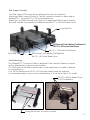
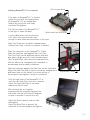
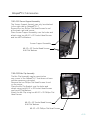
INSTALLATION INSTRUCTIONS
Product
Revision
Notepad™V-LT Universal Cradle & Accessories
7160-0402 Notepad™V-LT Universal Cradle
7160-0251 Screen Support Assembly
7160-0252 LED Light Assembly
7160-0253 Mic Clip Assembly
Form
INST-562
Rev. A
Printing Spec: PS-001
7160-0250 Notepad™V-LT Universal Cradle w/Standard Side Clips
Notepad™V-LT Universal Computer Mount 7160-0402 will accomodate
computers 8.2" to 11.8" in width, 7.58" to 9.3" in depth and up to 1.50" thick.
The Notepad™V-LT hold-down clips and key lock are designed to securely hold the laptop
in the mount and deter theft, not prevent it.
Gamber-Johnson recommends taking your laptop out of the vehicle when not in use.
9/64" Hex (Allen) wrench is needed to adjust clip location and postion. 7/16" Wrench or
Socket is need to attach Notepad™V-LT to Gamber-Johnson Motion Attachments.
#2 Phillips screwdriver and a 9/64" Hex (Allen) wrench are need to mount accessories.
Vinyl Cap
Side Clips
Long Rear Clip
Rear Support & Brace
Deck
Short Rear Clip
Flat Front Clip
Lockable Latch
Clip Guide
Tee Nut
Offset Front Clip
Product Mounting Disclaimer
Gamber-Johnson is not liable under any theory of contract or tort law for any loss, damage, personal injury, special, incidental or consequential damages for personal injury or other damage
of any nature arising directly or indirectly as a result of the improper installation or use of its products in vehicle or any other application. In order to safely install and use Gamber-Johnson
products full consideration of vehicle occupants, vehicle systems (i.e., the location of fuel lines, brakes lines, electrical, drive train or other systems), air-bags and other safety equipment is
required. Gamber-Johnson specifically disclaims any responsibility for the improper use or installation of its products not consistent with the original vehicle manufactures specifications
and recommendations, Gamber-Johnson product instruction sheets, or workmanship standards as endorsed through the Gamber-Johnson Certified Installer Program.
© copyright 2011 Gamber-Johnson, LLC
If you need assistance or have questions, call Gamber-Johnson at 1-800-456-6868
1/5
Rear Support Assembly
Two Rear Support Clips must be assembled at the time of installation.
Attach each Rear Support & Brace to Tee Nut located in channel on back edge of
Notepad™V-LT using a #8-32 x .38 Socket Head Screw.
Attach the Long Rear Clip and Short Rear Clip to appropriate Rear Support & Brace
with a #8 external tooth washer, Flat Washer and a #8-32 x .38 Socket Head Screw.
Long Rear Clip
#8 External Tooth Washer, Flat Washer &
#8-32 x .38 Socket Head Screw
Short Rear Clip
#8-32 x .38 Socket Head Screw
#8 External Tooth Washer, Flat Washer &
#8-32 x .38 Socket Head Screw
Vehicle Mounting
The Notepad™V-LT Universal Cradle is designed to be used with Gamber-Johnson
motion attachments, poles and vehicle bases.
The Sliding Mount Bar feature allows side-to-side adjustment of cradle to desired
mounting position.
Four .25 Flat Washers and .25-20 x .62 long Hex Head Screws are supplied
in the hardware bag to secure motion attachments to the bottom side of the cradle.
.25-20 x .62 Hex Head Screws
& .25 Flat Washers
Sliding Mount Bars on bottom surface
2/5
Pull to open deck
Adjusting Notepad™V-LT for computer
If the latch on Notepad™V-LT is locked,
unlock the unit with the supplied keys.
All Notepad™V-LT's are keyed alike.
Unlatch by turning the lock body
clockwise 90 degrees.
Pull the lock side of the Notepad™V-LT
to the right to open the deck.
Unlock and turn lock body
Loosen adjustment screws securing
front clips, rear clips and side clips
enough to raise them and move them in the slots.
Eight Vinyl Caps are included in hardware bag
to place over clips to protect computer if needed.
Optional Vinyl Caps
Place the computer on the Notepad™V-LT deck.
Slide the computer tight against the Front Clips.
The Front Clips can be adjusted side-to-side and
also have a slight amount of vertical adjustment.
The Flat and Offset clips may also swap positions,
with the offset clip overlapping the fixed deck to
accomodate shorter depth computers.
Slide the computer against the Side Clips on the fixed deck.
Adjust the Side Clips side-to-side to avoid any needed ports
and lower them so the tab will just clear the top of
the computer and tighten. A snug fit is prefered.
Adjustment Screw
Push the right side of the Notepad™V-LT in
until the right Side Clips touch the computer.
Adjust the right Side Clips in the same
manner as the left side.
After pushing the unit together,
(compressing the computer between the
side clips) turn the lock body 90 degrees
counter-clockwise to secure the unit.
Adjust the Rear Supports side-to-side
and tighten.
Adjust the Rear Clips to prevent the
computer from moving back and tighten.
3/5
Notepad™V-LT Accessories
7160-0251 Screen Support Assembly
The Screen Support Assemly can only be attached
to the right side on Notepad™V-LT.
Remove the two Phillips Flat Head Screws found
at the back right side corner.
Place Screen Support Assembly over the holes and
attach using two #8-32 x .62 Socket Head Screws
and two #8 Flat Washers.
Screen Support Assembly
#8-32 x .62 Socket Head Screws
& #8 Flat Washers
7160-0253 Mic Clip Assembly
The Mic Clip Assembly can be mounted on
any corner of the Notpad™V-LT that does not have
another accessory mounted.
Remove the two Phillips Flat Head Screws found
on the corner.
Place the Mic Clip Bracket over the holes and
attach using two #8-32 x .62 Socket Head Screws
and two #8 Flat Washers.
Attach the Mic Clip using two #6-32 x .25 Phillips Flat
Head Screws
#8-32 x .62 Socket Head Screws
& #8 Flat Washers
#6-32 x .25 Phillips Flat Head Screws
4/5
Notepad™V-LT Accessories Cont.
7160-0252 LED Light Assembly
The LED Light Assembly can be mounted on
any corner of the Notpad™V-LT.
Remove the two Phillips Flat Head Screws found
on the corner.
Place the LED Light Assembly over the holes and
attach using two #8-32 x .62 Socket Head Screws
and two #8 Flat Washers.
LED Light Assembly
#8-32 x .62 Socket Head Screws
& #8 Flat Washers
The LED is powered using the red and
black wires on the light base.
The LED Assembly is designed to operate on 12 VDC.
In a negative ground vehicle:
Connect the RED wire to the positive pole of the
vehicle battery or power distribution box.
It is recommended that a user-supplied fuse holder
and 1 amp fuse be installed on the red wire.
Connect the BLACK wire to a suitable chassis GROUND
or the NEGATIVE pole of the battery.
Turn on the LED by pressing the Activation Button
on the head on the LED Assembly.
The LED has three light options: White, Red and White/Red.
Press the Activation Button to toggle thru the options.
Activation Button
Hold the Activation Button down for approximately one second to turn the LED off.
5/5