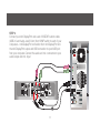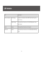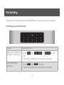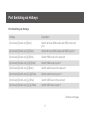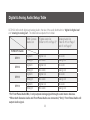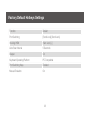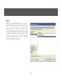
1
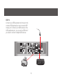
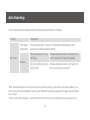
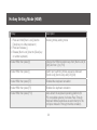
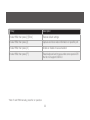
User Manual
4-Port DualView Mini DisplayPort KVMP Switch with Peripheral Sharing
1
GCS1924
PART NO. M1203
©2012 IOGEAR®. All Rights Reserved. PKG-M1203
IOGEAR, the IOGEAR logo, MiniView®, VSE are trademarks or registered trademarks of IOGEAR. Microsoft and Windows
are registered trademarks of Microsoft Corporation. IBM is a registered trademark of International Business Machines, Inc.
Macintosh, G3/G4 and iMac are registered trademarks of Apple Computer, Inc. IOGEAR makes no warranty of any kind
with regards to the information presented in this document. All information furnished here is for informational purposes only
and is subject to change without notice. IOGEAR assumes no responsibility for any inaccuracies or errors that may appear
in this document.
2
Table of Contents
Package Content
4
Mac Keyboard Emulation
24
System Requirements
5
Factory Default Hotkeys Settings
25
GCS1924 Overview
6
Firmware Upgrade
26
Installation9
Upgrade Fail
31
LED Indication
14
Federal Communications Commission (FCC)
Port Switching 15
Statement32
Port Switching via Hotkeys
17
CE Compliance 33
Auto Scanning
19
SJ/T 11364-2006
34
Hotkey Setting Mode (HSM)
20
Limited Warranty
35
Digital & Analog Audio Setup Table
23
Contact36
3
Package Content
––
––
––
––
––
––
––
––
1 x 4-port DualView Mini DisplayPort KVMP Switch
8 x Mini DisplayPort 1.1a Cable
4 x USB 2.0 Cable (Type A to Type B)
4 x 3.5mm Audio Cable (Green Head)
4 x 3.5mm Mic Cable (Pink Head)
1 x User Manuel
1 x Power Adapter
1 x Warranty Card
4
System Requirements
Console
–– Two mini DisplayPort Monitors
–– 1 x USB Keyboard
–– 1 x USB Mouse
–– Speaker / Microphone (Analog / Digital) – Optional *
* Front Audio Port supports Analog Audio output only
Computer
–– mini DisplayPort (Single / Dual mini DisplayPort Video card)
–– Type “A” USB Port
Operating System
–– Window XP / VISTA / 7
–– MAC OSX 10.5.4 or greater
5
GCS1924 Overview
Front View
1. Port 1 Touch Panel
2. Port 2 Touch Panel
3. Mode Touch Panel
4. Port 3 Touch Panel
5.
6.
7.
8.
1
Port 4 Touch Panel
Front Panel Console Mic. Connection (analog only)
Front Panel Console Audio Connection (analog only)
Front Panel USB 2.0 Peripheral Sharing Port (w/ Quick Charge)
2
3
6
4
5
6
7
8
Rear View
1. CPU 2 Mini DisplayPort 2B
2. CPU 2 Mini DisplayPort 2A
3. CPU 2 Mini-TOSLINK Mic.
(Digital/Analog)
4. CPU 2 Mini-TOSLINK Audio
(Digital/Analog)
5. CPU 2 USB Connection
6. CPU 1 Mini DisplayPort 1B
1
3
2
5
7. CPU 1 Mini DisplayPort 1A
8. CPU 1 Mini-TOSLINK Mic.
(Digital/Analog)
9. CPU 1 Mini-TOSLINK Audio
(Digital/Analog)
10.CPU 1 USB 2.0 Connection
11.Console USB 2.0 Peripheral
Sharing Port
4
12.Console Mini DisplayPort B
13.Console Mini DisplayPort A
14.Console Mini-TOSLINK Mic.
(Digital/Analog)
15.Console Mini-TOSLINK Audio
(Digital/Analog)
16.Console USB Mouse Port
17.Console USB Keyboard Port
18.DC Power Jack
6
8
9
12
14
7
10
7
11
13
16 17
15
18
Side View
6. CPU 3 Mini DisplayPort 3B
7. CPU 3 Mini DisplayPort 3A
8. CPU 3 Mini-TOSLINK Mic. Connection
(Digital/Analog)
9. CPU 3 Mini-TOSLINK Audio Connection
(Digital/Analog)
10.CPU 3 USB 2.0 Connection
1. CPU 4 Mini DisplayPort 4B
2. CPU 4 Mini DisplayPort 4A
3. CPU 4 Mini-TOSLINK Mic. Connection
(Digital/Analog)
4. CPU 4 Mini-TOSLINK Audio Connection
(Digital/Analog)
5. CPU 4 USB Connection
3
4
1
5
2
8
8
9
6
10
7
Installation
STEP 1
Please make sure your source devices and displays are powered off before you start.
STEP 2
Connect the mini DisplayPort cables
from your monitors to the console
mini DisplayPort A and/or B. Port A
will be your main monitor and Port
B will be your extended desktop
monitor.
B
9
A
STEP 3
Connect your USB keyboard and mouse to the
console USB keyboard port and console USB
mouse port. Connect your USB devices to the
USB peripheral port, you can add a USB hub if
you need to connect multiple USB devices.
10
STEP 4
Connect your mini DisplayPort and a set of IOGEAR custom cable
(USB 2.0 and Audio Jack 3.5mm) from KVMP switch to each of your
computers – mini DisplayPort connection from mini DisplayPort A to
the mini DisplayPort output and USB connection to open USB port
from your computer. Connect the audio and mic. connectors to your
audio output and mic. input
A
11
STEP 5
Connect mini DisplayPort cables from mini
DisplayPort B of the KVMP to your second mini
DisplayPort output of your computers. Repeat
the same for port #2, 3 and 4.
A
B
12
STEP 6
Plug the power adapter into the power outlet and
connect it to the DC power jack from the KVMP
Final Step
Installation is complete. Turn on your computers
and other devices and enjoy.
13
LED Indication
LED
Online / Selected
Description
Dim Orange
A device is connected to the KVMP switch but the port is
not on focus
Bright Orange
The specific port has focus on the KVM (Keyboard, video
and mouse)
Audio
Green
The specific port has focus on the audio
USB Link
Green
The specific port has focus on the USB peripheral sharing
ports
14
Port Switching
Simply touch the front panel from the multimedia KVMP switch or trigger hotkeys from your keyboard.
Port Switching via Front Panel Touch
Function
Touch Panel Control
Switch all focus (KVM, audio
and USB) to a specific port
1.Touch MODE once, KVM , AUDIO , and USB LINK LEDs will
flash
2.Then touch the specific port to switch all focus to that port
Switch KVM focus to a
specific port
1.Touch MODE twice, KVM LED will flash
2.Then touch the specific port to switch KVM port to that port
15
Switch audio focus to a
specific port
1.Touch MODE three times, AUDIO LEDs will flash
2.Then, touch the specific port to switch Audio port to that port
Switch USB focus to a
specific port
1.Touch MODE four times, USB LINK LED will flash
2.Then, touch the specific port to switch USB focus to that port
16
Port Switching via Hotkeys
Port Switching via Hotkeys
Hotkeys
Description
[Scroll Lock] [Scroll Lock] [Enter]
Switch all focus (KVM, audio and USB) to the next
port
[Scroll Lock] [Scroll Lock] [n] [Enter]
Switch all focus (KVM, audio and USB) to port n*
[Scroll Lock] [Scroll Lock] [k] [Enter]
Switch KVM focus to the next port
[Scroll Lock] [Scroll Lock] [n] [k] [Enter]
Switch KVM focus to port n*
[Scroll Lock] [Scroll Lock] [s] [Enter]
Switch audio focus to the next port
[Scroll Lock] [Scroll Lock] [n] [s] [Enter]
Switch audio focus to port n*
[Scroll Lock] [Scroll Lock] [u] [Enter]
Switch USB focus to the next port
[Scroll Lock] [Scroll Lock] [n] [u] [Enter]
Switch USB focus to port n*
Continue next page
17
Port Switching via Hotkeys
[Scroll Lock] [Scroll Lock] [n] [k] [u] [Enter]
Switch KVM and USB focus to port n*
[Scroll Lock] [Scroll Lock] [n] [k] [s] [Enter]
Switch KVM and audio focus to port n*
[Scroll Lock] [Scroll Lock] [n] [u] [s] [Enter]
Switch USB and audio focus to port n*
*Note: n is an interval that stands for the Port number
k stands for KVM focus
s stands for audio focus
u stands for USB focus
18
Auto Scanning
You can either activate Autoscan Mode via front panel push button or hotkeys.
Function
Description
Front panel
pushbutton
Auto Scan
Hotkeys
Press and hold port 1 and port 2 Pushbutton simultaneously for 2
seconds to activate Autoscan Mode*
[Scroll Lock] [Scroll Lock]
[a] [Enter]
Activate Autoscan mode. It will cycle from
port to port every 5 seconds (default)
[Scroll Lock] [Scroll Lock]
[a] [n] [Enter]
Activate Autoscan mode. It will cycle from
port to port every n seconds**
*Note: Autoscan Mode from front panel push button will be scanning a port every 5 seconds by default. If you
wish to have the Autoscan Mode be scanning with different time interval, please refer to trigger Autoscan Mode
from hotkeys.
**Note: n is an interval between 1 and 99 that stands for the time (in second) desired for scanning each port.
19
Hotkey Setting Mode (HSM)
Hotkey
Description
1. Press and hold [Num Lock] (Use the
[Clear] key on a Mac keyboard.)
2. Press and release [-]
3. Release [Num Lock] (Use the [Clear] key
on a Mac keyboard.)
Invoking hotkey setting mode
Invoke HSM, then press [h]
Change the HSM invocation keys from [Num Lock] to
[Ctrl] and from [-] to [F12]
Invoke HSM, then press [t]
Switch port switching hotkey sequence between
[Scroll Lock] [Scroll Lock] and [Ctrl] [Ctrl]
Invoke HSM, then press [F2]
Enables Mac keyboard emulation
Invoke HSM, then press [F3]
Enables Sun keyboard emulation
Invoke HSM, then press [F10]
Auto-detect the keyboard operating platform (for
PC compatible systems). Activates Pass Through
Keyboard Mode (keystrokes are sent directly to the
computer instead of through the Mac emulator).
20
Hotkey
Description
Invoke HSM, then press [l]
Quick charge mode
Invoke HSM, then press [e]
power on detection
Invoke HSM, then press [n] + [enter]
enables game mode
Invoke HSM, then press [w]
mouse port switch
Invoke HSM, then press [F4]
List hotkey settings – simply invoke the hotkey and
then open a text editor, such as notepad, and use
the Paste function to display the hotkey settings.
Invoke HSM, then press [F5]
USB Reset
Invoke HSM, then press [b]
Toggle hotkey beepers on or off
Invoke HSM, then press [x] [Enter]
Disable or enable port switching hotkey
Invoke HSM, then press [u] [p] [g] [r] [a] [d] [e]
[Enter]
Activate Firmware Upgrade Mode – Front panel KVM
LED will flash indicating Firmware Upgrade Mode is
activated.
21
Hotkey
Description
Invoke HSM, then press [r] [Enter]
Restore default settings
Invoke HSM, then press [d]
Capture and store video information on specific port
Invoke HSM, then press [m]
Enable or disable mouse emulation
Invoke HSM, then press [F1]
Reset keyboard and mouse under some special OS’
that do not support USB 2.0
*Note: To exit HSM manually, press Esc or spacebar
22
Digital & Analog Audio Setup Table
GCS1924 offers both digital and analog Audio; the rule of the audio distribution is “digital in digital out”
and “analog in analog out”. The table below explains this in detail.
KVM Console
Audio Out
"Digital Audio Out
(Refer to #15 on Page 7)"
"Analog Audio Out
(Refer to #15 on Page 7
and #7 on Page 6)"
Digital In
Digital Out
No Audio
Analog In
No Audio
Analog Out
Digital In
Digital Out
No Audio
Analog In
No Audio
Analog Out
Digital In
Digital Out
No Audio
Analog In
No Audio
Analog Out
Digital In
Digital Out
No Audio
Analog In
No Audio
Analog Out
KVM CPU Audio
CPU 1
CPU 2
CPU 3
CPU 4
*For Front Panel Audio/Mic, it only outputs Analog signal through sound stereo devices.
**When both Console Audio and Front Panel Audio are connected, “Only” Front Panel Audio will
output Audio signal.
23
Mac Keyboard Emulation
The PC compatible (101/104 key) keyboard can emulate the functions of the Mac keyboard. The
emulation mappings are listed in the table below.
PC Keyboard
Mac Keyboard
PC Keyboard
Mac Keyboard
[Shift]
Shift
[Print Screen]
F13
[Crtl]
Ctrl
[Scroll Lock]
F14
=
[Ctrl] [1]
[Enter]
Return
[Ctrl] [2]
[Backspace]
Delete
[Ctrl] [3]
[Insert]
Help
[Ctrl] [4]
[Ctrl]
F15
[Alt]
Alt
*Note: When using key combinations, press and release the first key (Ctrl), then press and release the
second key.
24
Factory Default Hotkeys Settings
Function
Default
Port Switching
[Scroll Lock] [Scroll Lock]
Invoking HSM
[Num Lock] [-]
Auto Scan Interval
5 Seconds
Beeper
On
Keyboard Operating Platform
PC Compatible
Port Switching Keys
Enabled
Mouse Emulation
On
25
Firmware Upgrade
Note: In order to perform a firmware upgrade, you need to use a computer that’s not connected to the
KVM.
Step 1
Connect the provided firmware upgrade cable to the firmware upgrade port of the KVM and the serial port
of your computer. Connect power adapter to your power outlet and the KVM.
Step 2
Go to www.iogear.com to download the latest available firmware or the specific firmware that you wish to
upgrade to.
Step 3
Shut down all the computers that are connected to the KVM. Then Invoke Firmware Upgrade Mode.
(Please refer to Hotkeys Setting Mode section.)
Step 4
Extract the file with WinRAR or compatible software. Then double click on the execute file to begin with the
Firmware Upgrade Utility.
26
Step 5
Read the License Agreement and click “I
Agree” then click “Next” if you wish to continue
with the firmware upgrade. Otherwise, click
“Cancel” to exit.
27
Step 6
Choose the correct KVM that you wish to
perform firmware upgrade from the “Device
List” and then click “Next” to continue. Then
the Firmware Upgrade Utility will verify if there
is a KVM connected to the computer by the
firmware upgrade cable. (Check Firmware
Version checkbox is optional)
28
Step 7
If you have checked the “Check Firmware Version” checkbox, then the utility will check the current firmware
that is on your KVM. If the current firmware is newer than the firmware that you wish to upgrade to, a window
will popup and prompt you to ask if you wish to proceed. Simply click “Yes” to start the upgrade and “No”
to cancel the upgrade.
Note: If you did not check the “Check Firmware Version” checkbox, utility will perform the upgrade
automatically no matter what version of firmware you have in the KVM.
29
Step 8
When the firmware upgrade is done, you will
see “Firmware upgrade OK” in the “Status
Messages” window. Then simply click “Finish”
to complete the whole firmware upgrade
process.
Final Step
Now the KVM will reset by itself and it will be
ready for usage after the rest.
Note: If you see warring message of Mac O.S.
version incompatible, please contact IOGEAR
service staff for latest firmware upgrade tool
30
Upgrade Fail
If you don’t see “Firmware upgrade OK” in the “Status Messages” window, it means the utility has failed to
complete the firmware successfully. If that occurs, please do the following:
Step 1
Unplug all USB cables and DC power adapter from GCS1924.
Step 2
Plug single USB cable in the last CPU port with PC powered on.
Step 3
Plug DC power adapter, the GCS1924's port LED will start flash after powered on.
Step 4
Run FW upgrade program again
31
Federal Communications Commission (FCC) Statement
This equipment has been tested and found to comply with the limits for a Class B digital
device, pursuant to Part 15 of the FCC Rules. These limits are designed to provide reasonable
protection against harmful interference in a residential setting. This product generates, uses,
and can radiate radio frequency energy and, if not installed and used as directed, it may cause
harmful interference to radio communications. Although this product complies with the limits
for a Class B digital device, there is no guarantee that interference will not occur in a particular
installation.
32
CE Compliance
This device has been tested and found to comply with the following European Union
directives: Electromagnetic Capability (89/336/EMC), Low Voltage (73/23/EEC) and
R&TTED (1999/5/EC).
33
SJ/T 11364-2006
The following contains information that relates to China.
有毒有害物质或元素
部件名称
铅 (Pb)
汞 (Hg)
镉(Cd)
多溴联苯
多溴二苯醚
(PBB)
(PBDE)
六价 (Cr(VI))
电器部件
●
○
○
○
○
○
机构部件
○
○
○
○
○
○
○:表示该有毒有害物质在该部件所有均质材料中的含量均在SJ/T 11363-2006规定的限量要求之下。
●:表示符合欧盟的豁免条款,但该有毒有害物质至少在该部件的某一均质材料中的含量超出
SJ/T 11363-2006的限量要求。
×:表示该有毒有害物质至少在该部件的某一均质材料中的含量超出SJ/T 11363-2006的限量要求。
34
Limited Warranty
WE’RE HERE TO HELP YOU!
NEED ASSISTANCE SETTING UP THIS PRODUCT?
Make sure you:
1. Visit www.iogear.com for more product information
2. Visit www.iogear.com/support for live help and product support
Warranty Information
This product carries a 3 Year Limited Warranty. For the terms and conditions of this warranty,
please go to http://www.iogear.com/support/warranty
Register online at http://www.iogear.com/register
Important Product Information
Product Model
Serial Number
35
Contact
IOGEAR
Toll Free 866-9-IOGEAR (USA)
Phone: 949-453-8782
19641 Da Vinci, Foothill Ranch, CA92610
www.iogear.com
[email protected]
36
37
About Us
FUN
IOGEAR offers connectivity solutions that are innovative, fun, and
stylish, helping people enjoy daily life using our high technology
products.
GREEN
IOGEAR is an environmentally conscious company that
emphasizes the importance of conserving natural resources. The
use of our technology solutions helps reduce electronic waste.
38
© 2012 IOGEAR®