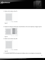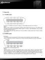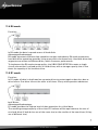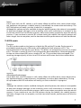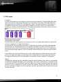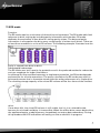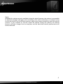
1
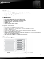
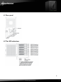
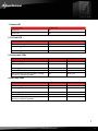
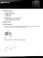
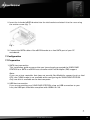
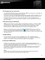
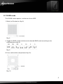
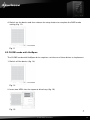
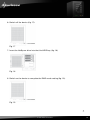
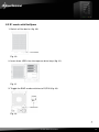
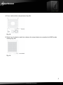
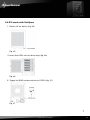
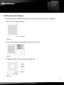
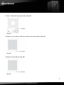
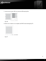
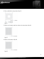
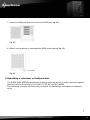
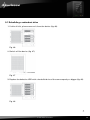
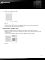
5-BAY RAID STATION Manual Content 1. Features 1.1 Overview 1.2 SATA features 1.3 USB features 2. Specifications 3. System requirements 4. The device at a glance 4.1 Rear panel 4.2 The LED indications 5. Package contents 6. Getting started 6.1 HDD installation 6.2 Power on/off 6.3 eSATA slot bracket installation 7. Configuration 7.1 Preparation 7.2 Changing the host connection 7.3 Disconnecting an USB device 7.4 HDD HotPlug 8. Setting the RAID mode 8.1 CLEAN mode 8.2 CLONE mode with HotSpare 8.3 R1 mode with HotSpare 8.4 R10 mode with HotSpare 8.5 R3 mode with HotSpare 8.6 R5 mode with HotSpare 9. Rebuilding a redundant or HotSpare drive 9.1 Rebuilding a redundant drive 9.2 Rebuilding a HotSpare drive 10. Troubleshooting 11. Appendix 11.1 CLEAN mode 11.2 LARGE mode 11.3 CLONE mode 11.4 R0 mode 11.5 R1 mode 11.6 R10 mode 11.7 R3 mode 11.8 R5 mode 3 3 3 4 4 4 4 5 5 7 7 7 9 9 10 10 11 11 11 11 12 13 16 18 20 23 25 26 27 29 30 30 30 31 32 32 33 34 35 5-bay raid station 2 Dear customer! Congratulations for purchasing one premium quality SHARKOON product. For a long life time and to take full advantage of this product we recommend that you read this manual completely. Have a good time with our product! SHARKOON Technologies 1. Features 1.1 Overview • • • • • • • • • • • • • External RAID case with five mounting bays for 2.5" and 3.5" SATA HDDs Supported modes: Clean/Single, Large, Clone and RAID 0/1/3/5/10 Easy RAID mode configuration Automatic rebuild in Clone and RAID 1/3/5/10 mode HotSpare support in Clone and RAID 1/3/5/10 mode Supports HDD roaming Internal interfaces: SATA I and II (compatible with SATA III) External interfaces: eSATA and USB3.0 Fast Swap mechanism for easy HDD handling Premium quality craftsmanship On/off button LED indications for power, HDD activity and rebuild mode Pre-installed fan 1.2 SATA features • • • • • • • • • • Port Multiplier Functionality Auto-negotiation between SATA I (1.5 Gbps) and SATA II (3 Gbps) Hot-Plug support in CLEAN mode Supports Native Command Queue (NCQ) Supports Port Multiplier Aware and non-Port Multiplier Aware host in RAID mode Supports Asynchronous Signal Recovery Supports Spread Spectrum Clocking Supports BIST and Loopback mode Supports 48-bit LBA addressing Supports Asynchronous Notification 5-bay raid station 3 1.3 USB features • Compatible with USB Super Speed, High Speed and Full Speed • Compatible with OHCI/UHCI/EHCI hosts • Supports Mass Storage Class 2. Specifications • • • • • Five mounting bays for 2.5" and 3.5" SATA HDDs Metal chassis (SECC) and plastic front panel (ABS) Dimensions: 282 x 150 x 215 mm (L x W x H) Weight: ~4 kg 250 W full range power supply 3. System requirements • • • • • • • Intel Pentium-III 500 MHz equivalent or faster Windows XP, Windows Vista, Windows 7 with the latest Service Packs 64 MB of RAM (minimum) Super VGA (800 x 600) or higher resolution display with at least 256 colors Mouse or compatible pointing device SATA connection: Intel ICH or optional Host Bus Adapter card and associated software drivers with Port Multiplier support USB connection: USB 2.0 or 3.0 direct host connection 4. The device at a glance 5-bay raid station 4 4.1 Rear panel 4.2 The LED indications 5-bay raid station 5 1. Power LED DESCRIPTION GREEN LED Power On On Power Off Off 2. PC Link LED DESCRIPTION GREEN LED PC Link Unplugged / No Power Off PC Link Plugged (Idle) On PC Link Plugged (Active) On 3. Front panel LEDs DESCRIPTION GREEN LED RED LED HDD Unplugged / No Power Off Off HDD Plugged (Idle) On Off HDD Plugged (Active) Blink (On) Off Error State (one or more bad partial volumes) Off On HDD Rebuild (a physical partition is being rebuild; e.g. Mirroring Mode) Off Blink (On) DESCRIPTION GREEN (UPPER) GREEN (LOWER) HDD Unplugged / No Power Off Off HDD Plugged (Idle) On Off HDD Plugged (Active) Blink (On) Off Error State (one or more bad partial volumes) Off On HDD Rebuild (a physical partition is being rebuild; e.g. Mirroring Mode) On Blink (On) 4. HDD tray LEDs 5-bay raid station 6 5. Package contents • • • • • • • • 5-Bay RAID Station 5x HDD mounting frames 1x USB3.0 cable 1x eSATA cable 1x power cord 20x mounting screws for 2.5" HDDs/SSDs 20x mounting screws for 3.5" HDDs 1x SATA to eSATA cable with bracket 6. Getting started 6.1 HDD installation 1. Open the front door, then unlock the HDD mounting frame lock and remove the HDD mounting frame from the 5-BAY RAID STATION (fig. 1). Fig. 1 2. Place the HDD into the HDD mounting frame (fig. 2). Fig. 2 5-bay raid station 7 3. Use the mounting screws to securely attach the HDD to the mounting frame (fig. 3). Fig. 3 4. Slide the HDD mounting frame back into the 5-BAY RAID STATION (fig. 4). Fig. 4 5. Close the front door to complete the HDD installation (fig. 5). Fig. 5 5-bay raid station 8 6.2 Power on/off Press the power button to switch on the device. Press again to power it off. 6.3 eSATA slot bracket installation 1. Remove the anchor screw of the slot bezel and take it from the rear side of your PC case (fig. 6). Fig. 6 5-bay raid station 9 2. Insert the included eSATA bracket into the slot bracket and attach it to the case using the anchor screw (fig. 7). Fig. 7 3. Connect the SATA cable of the eSATA bracket to a free SATA port of your PC mainboard. 7. Configuration 7.1 Preparation 1. SATA host connection This installation guide assumes that you have already connected the 5-BAY RAID STATION to a SATA or eSATA host controller with Port Multiplier (PM) support. Note: If you use a host controller that does not provide Port Multiplier support (such as Intel ICH), the CLEAN mode is not available when configuring the 5-BAY RAID STATION. Only one disk is available on the host computer. 2. USB host connection If you are connecting your 5-BAY RAID STATION using an USB connection to your host, the USB port should be compliant with USB2.0 or 3.0. 5-bay raid station 10 7.2 Changing the host connection The 5-BAY RAID STATION supports both USB and eSATA host connections, although only one connection can be attached at the same time. If it becomes necessary to switch the host connection between eSATA and USB, the host computer system and the 5-BAY RAID STATION should both be powered down prior to changing the host connection, in order to avoid data loss. After changing the host connection, both devices can be powered-on again to continue operation with the new host connection. 7.3 Disconnecting an USB device USB3.0 external devices provide support for Plug & Play connection, so that your USB storage device can be connected and disconnected while the computer is running. To prevent data loss or other failures, we recommend the following procedure when disconnecting your USB3.0 storage device from your host computer system: Before you shut down your PC remove the 5-Bay RAID Station from your system’s hardware configuration by double-clicking the symbol in the task bar. A menu will open up. Select the 5-Bay RAID Station to securely remove it. Switch off the device and shut down your PC. 7.4 HDD HotPlug The hard disk drives should not be hot-plugged, but can be unplugged while the system is running. However, to avoid data corruption or loss, make sure that the host system is not currently using any drive that is about to be unplugged. 8. Setting the RAID mode To define a storage mode for the first time, make sure that the hard disk drives are mounted, then turn off the power before setting the RAID MODE SWITCHES on the rear side of the 5-BAY RAID STATION to the desired mode. To change the storage mode afterwards, set the RAID mode switches to the desired position. Press and hold the setup button, then switch on the device to create the new virtual volume(s). Notes: Creating new virtual volumes will erase any existing data saved on the volumes! Back up your data before reconfiguring the storage mode! 5-bay raid station 11 8.1 CLEAN mode The CLEAN mode requires a minimum of one HDD. 1. Switch off the device (fig. 8). Fig. 8 2. Toggle the RAID mode switches to the desired RAID mode according to the following chart (fig. 9): Fig. 9 3. Press and hold the setup button (fig. 10). Fig. 10 5-bay raid station 12 4. Switch on the device and then release the setup button to complete the RAID mode setting (fig. 11). Fig. 11 8.2 CLONE mode with HotSpare The CLONE mode with HotSpare drive requires a minimum of three drives to implement. 1. Switch off the device (fig. 12). Fig. 12 2. Insert two HDDs into the topmost drive bays (fig. 13). Fig. 13 5-bay raid station 13 3. Toggle the RAID mode switches to CLONE (fig. 14). Fig. 14 4. Press and hold the setup button (fig. 15). Fig. 15 5. Switch on the device and then release the setup button (fig. 16). Fig. 16 5-bay raid station 14 6. Switch off the device (fig. 17). Fig. 17 7. Insert the HotSpare drive into the third HDD bay (fig. 18). Fig. 18 8. Switch on the device to complete the RAID mode setting (fig. 19). Fig. 19 5-bay raid station 15 8.3 R1 mode with HotSpare 1. Switch off the device (fig. 20). Fig. 20 2. Insert three HDDs into the topmost drive bays (fig. 21). Fig. 21 3. Toggle the RAID mode switches to R1/R10 (fig. 22). Fig. 22 5-bay raid station 16 4. Press and hold the setup button (fig. 23). Fig. 23 5. Switch on the device and then release the setup button to complete the RAID mode setting (fig. 24). Fig. 24 5-bay raid station 17 8.4 R10 mode with HotSpare 1. Switch off the device (fig. 25). Fig. 25 2. Insert five HDDs into the drive bays (fig. 26). Fig. 26 3. Toggle the RAID mode switches to R1/R10 (fig. 27). Fig. 27 5-bay raid station 18 4. Press and hold the setup button (fig. 28). Fig. 28 5. Switch on the power and then release the setup button to complete the RAID mode setting (fig. 29). Fig. 29 5-bay raid station 19 8.5 R3 mode with HotSpare The R3 mode with HotSpare HDD requires a minimum of four drives to implement. 1. Switch off the device (fig. 30). Fig. 30 2. Insert three drives into the topmost drive bays (fig. 31). Fig. 31 3. Toggle the RAID mode switches to R3 (fig. 32). Fig. 32 5-bay raid station 20 4. Press and hold the setup button (fig. 33). Fig. 33 5. Switch on the device and then release the setup button (fig. 34). Fig. 34 6. Switch off the device (fig. 35). Fig. 35 5-bay raid station 21 7. Insert the hot spare HDD into the 4th HDD bay (fig. 36). Fig. 36 8. Switch on the device to complete the RAID mode setting (fig. 37). Fig. 37 5-bay raid station 22 8.6 R5 mode with HotSpare The R5 mode with HotSpare HDD requires a minimum of four drives to implement. 1. Switch off the device (fig. 38). Fig. 38 2. Insert three drives into the topmost drive bays (fig. 39). Fig. 39 3. Toggle the RAID mode switches to R5 (fig. 40). Fig. 40 5-bay raid station 23 4. Press and hold the setup button (fig. 41). Fig. 41 5. Switch on the device and then release the setup button (fig. 42). Fig. 42 6. Switch off the device (fig. 43). Fig. 43 5-bay raid station 24 7. Insert the HotSpare drive into the fourth HDD bay (fig. 44). Fig. 44 8. Switch on the device to complete the RAID mode setting (fig. 45). Fig. 45 9. Rebuilding a redundant or HotSpare drive The 5-BAY RAID STATION duplicates all data to separate drives in order to protect against data loss due to drive failure in CLONE, R1, R3, R5, and R10 MODE. The following example illustrates the procedure of rebuilding a redundant or HotSpare drive. 5-bay raid station 25 9.1 Rebuilding a redundant drive 1. If drive 2 fails, please remove it from the device (fig. 46). Fig. 46 2. Switch off the device (fig. 47). Fig. 47 3. Replace the defective HDD with a hard disk drive of the same capacity or bigger (fig. 48). Fig. 48 5-bay raid station 26 4. Switch on the device (fig. 49). Fig. 49 5. The 5-BAY RAID STATION will start rebuilding the virtual volume automatically (rebuild speed: approximately 200 GB/hour). 9.2 Rebuilding a HotSpare drive 1. If there is a HotSpare drive inserted into drive bay 5, and the drive 2 fails, the HotSpare drive 5 will replace the broken down drive. The rebuild procedure will start automatically. To install a new HotSpare drive, remove the defective drive 2 (fig. 50). Fig. 50 5-bay raid station 27 2. Switch off the device (fig. 51). Fig. 51 3. Replace the defective HDD with a hard disk drive of the same capacity or bigger (fig. 52). Fig. 52 4. Switch on the device (fig. 53). Fig. 53 5. The 5-BAY RAID STATION will replace the HotSpare drive in mounting bay 2 automatically. 5-bay raid station 28 10. Troubleshooting 1. Device is not recognized Make sure all cables have been properly connected. For the USB3.0 controller the latest drivers and the newest firmware must be installed. 2.Cannot operate in O/S Make sure the device is supported by your operating system. 3.Transfer speed is slow If the device is connected via the USB2.0 interface, the speed will be around 30 MB/sec only. 4.When formatting under Windows XP/Vista/7, the dialog box “Unfinished formatting” is displayed Windows XP/Vista/7 cannot format HDDs with capacities above 32 GB into FAT32, please choose NTFS as data format. 5.Can the LARGE mode be used, when HDDs with different capacities or brand are built in? Yes. 6.When the system is damaged in LARGE mode, is it still possible to read the data? No. The system is different from a RAID; the entire disk cannot be read. 5-bay raid station 29 11. Appendix 11.1. CLEAN mode Function: In CLEAN mode each hard drive is displayed separately as one drive. Notes: When using a SATA host controller, CLEAN mode should only be used if the SATA host controller provides Port Multiplier (PM) support. If a host is not PM-aware, only a single drive is displayed (drive 1). The CLEAN mode will not delete the drives partition if the drives were used as single drive before. 11.2 LARGE mode Function: The LARGE mode concatenates a series of physical hard drives into a single large volume, creating a seamless expansion of virtual volumes beyond the physical limitations of singularly connected hard drives. Notes: The hard drives 1 to 5 are concatenated into a single virtual volume in the figure above with a storage capacity that is equal to the sum of each of the physical hard drives 1 to 5. It is also possible to create a LARGE volume using only a single hard disk drive connected to Port 1. However, it is not possible to expand an existing LARGE volume by adding another hard disk drive and still preserve any existing data on that volume. 5-bay raid station 30 11.3 CLONE mode Function: The CLONE mode duplicates all data on separate drives to protect against data loss due to drive failure. One drive clones the others at all times. Every write operation goes to all drives. Advantage: CLONE mode provides the highest level of data protection for critical data. The resulting storage capacity of the virtual CLONE volume will be equivalent to the size of one hard drive (if all drives are the same) or the smallest of the drives (if they are different). If a drive fails (maximum four drives), the CLONE volume is still usable. When the offline drive comes back online, the appliance begins a rebuild process immediately one by one (in case more than one HDD failed) to restore the data. During this procedure the LED indications will notify you that a rebuild is in progress. Notes: Although the volume remains available during the rebuild process, the volume is susceptible to data loss through damage to the remaining drive until redundancy is restored at the end of the rebuild and verification process. Host access takes precedence over the rebuild process. If you continue to use the CLONE volume during the rebuild, the rebuild process will take a longer time to complete, and the host data transfer performance will also be affected. It is also possible to create a CLONE volume using one hard disk drive connected to Port 1 of the 5-BAY RAID STATION, although no clone will occur until a second hard disk drive is connected. With only one hard disk drive connected, the CLONE volume will be available, although no data protection will be provided until a second hard disk drive is connected. 5-bay raid station 31 11.4 R0 mode Function: In R0 mode the data is spread across all hard disks. Advantage/disadvantage: R0 mode represents the best data speed but no data redundancy. R0 mode accelerates hard disk drive operating speed by using many disks simultaneously. Hard disk drive data segments are written to different disks, which increases performance. To implement the R0 mode storage policy, the 5-BAY RAID STATION creates a single virtual volume that is striped across all hard drives, with a storage capacity that is five times the capacity of the smallest drive. 11.5 R1 mode Function: In R1 mode all data is duplicated on separate drives to protect against data loss due to drive failure. One drive mirrors the other at all times. Every write operation addresses both drives. Advantage/disadvantage: R1 mode provides the highest level of data protection for critical data. The resulting storage capacity of the virtual R1 volume will be equivalent to the size of one hard drive (if both drives are of the same size) or the smaller of the two drives (if they are of different size). 5-bay raid station 32 Notes: If one drive fails, the R1 volume is still usable. When the offline drive comes back online, the appliance commences a rebuild process immediately to restore data redundancy. The LED indications will notify you that a rebuild is in progress. Although the volume remains available during the rebuild process, the volume is susceptible to data loss through damage to the remaining drive until redundancy is restored at the end of the rebuild and verification process. Host access takes precedence over the rebuild process. If you continue to use the R1 volume during the rebuild, the rebuild process will take a longer time to complete, and the host data transfer performance will also be affected. 11.6 R10 mode Function: The R10 mode combines the features of both the R0 and the R1 mode. Performance is provided through the use of R0 mode, while adding the fault tolerance of R1. The implementation of R10 requires four drives. The drives are assigned as two sets of striped pairs. The data is written to the R1 set and provides data redundancy. Alternating blocks of data are then striped (R0) across another R1 set. This provides improved speed. The resulting storage capacity of the virtual R10 volume will be two times the smallest drive capacity. Advantage/disadvantage: If one drive fails, the R10 volume is still usable. When the offline drive comes back online, the appliance begins a rebuild process immediately to restore data redundancy. During this procedure the LED indications will notify you that a rebuild is in progress. Notes: Although the volume remains available during the rebuild process, the volume is susceptible to data loss through damage to the remaining drive until redundancy is restored at the end of the rebuild and verification process. Host access takes precedence over the rebuild process. If you continue to use the R10 volume during the rebuild, the rebuild process will take a longer time to complete, and the host data transfer performance will also be affected. 5-bay raid station 33 11.7 R3 mode Function: The R3 mode requires a minimum of three drives to implement. The R3 mode adds fault tolerance to drive striping by adding parity information to the data. R3 mode dedicates the equivalent of one drive for storing parity stripes. The data and parity information is arranged on the drive array so that parity is written to one drive. There are at least three volumes to create a virtual R3 volume. The following example illustrates how the parity is rotated from drive to drive. Advantage/disadvantage: The R3 mode uses less capacity for protection and is the preferred method to reduce the cost per megabyte for larger installations. In exchange for low overhead necessary to implement protection, the R3 mode degrades performance for all write operations. The parity calculations for R3 mode may result in write performance that is somewhat slower than the write performance to a single drive. The resulting storage capacity of the virtual R3 volume will be four times of the smallest drive. If one drive fails, the virtual R3 volume is still usable. When the offline drive comes back online, the appliance begins a rebuild process immediately to restore data redundancy. During this procedure the LED indications will notify you that a rebuild is in progress. Notes: Although the volume remains available during the rebuild process, the volume is susceptible to data loss through damage to the remaining drive until redundancy is restored at the end of the rebuild and verification process. Host access takes precedence over the rebuild process. If you continue to use the virtual R3 volume during the rebuild, the rebuild process will take a longer time to complete, and the host data transfer performance will also be affected. 5-bay raid station 34 11.8 R5 mode Function: The R5 mode requires a minimum of three drives to implement. The R5 mode adds fault tolerance to drive striping by including parity information with the data. R5 mode dedicates the equivalent of one drive for storing parity stripes. The data and parity information is arranged on the drive array so that parity is written to all drives. There are at least three members to a virtual R5 volume. The following example illustrates how the parity is rotated from drive to drive. Advantage/disadvantage: The R5 mode uses less capacity for protection and is the preferred method to reduce the cost per megabyte for larger installations. In exchange for low overhead necessary to implement protection, the R5 mode degrades performance for all write operations. The parity calculations for R5 mode may result in write performance that is somewhat slower than the write performance of a single drive. The resulting storage capacity of the virtual R5 volume will be four times of the smallest drive. If one drive fails, the virtual R5 volume is still usable, but it is in a vulnerable state because its mirrored hard drive is inaccessible. When the offline drive comes back online, the appliance begins a rebuild process immediately to restore data redundancy. During this procedure the LED indications will notify you that a rebuild is in progress. 5-bay raid station 35 Notes: Although the volume remains available during the rebuild process, the volume is susceptible to data loss through damage to the remaining drive until redundancy is restored at the end of the rebuild and verification process. Host access takes precedence over the rebuild process. If you continue to use the virtual R5 volume during the rebuild, the rebuild process will take a longer time to complete, and the host data transfer performance will also be affected. 5-bay raid station 36 Legal disclaimer: For potential loss of data, especially due to inappropriate handling, SHARKOON assumes no liability. All named products and descriptions are trademarks and/or registered trademarks of the respective manufacturers and are accepted as protected. As a continuing policy of product improvement at SHARKOON, the design and specifications are subject to change without prior notice. National product specifications may vary. All rights reserved especially (also in extracts) for translation, reprinting, reproduction by copying or other technical means. Infringements will lead to compensation. All rights reserved especially in case of assignation of patent or utility patent. Means of delivery and technical modifications reserved. Disposal of your old product Your product is designed and manufactured with high quality materials and components, which can be recycled and reused. When this crossed-out wheeled bin symbol is attached to a product, it means the product is covered by the European Directive 2002/96/EC. Please be informed about the local separate collection system for electrical and electronic products. Please act according to your local rules and do not dispose of your old products with your normal household waste. The correct disposal of your old product will help prevent potential negative consequences to the environment and human health. © SHARKOON Technologies 2012 www.sharkoon.com 5-bay raid station 37