1
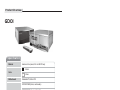
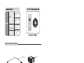
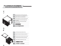
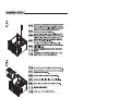
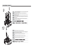
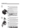
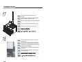
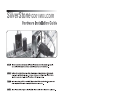
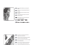
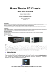
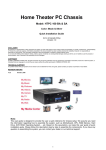
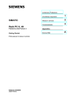
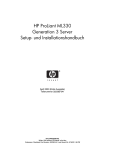
GD01
GRANDIA SERIES
MANUAL
Product Overview
GD01
Specification
Material
Aluminum front panel, 0.8 mm SECC body
Black
Color
Silver
Motherboard
Standard ATX, Micro ATX
SST-GD01B-R (black, card reader)
SST-GD01S-R (silver, card reader)
Model
SST-GD01B-MXR (black, multimedia, card reader)
SST-GD01S-MXR (silver, multimedia, card reader)
External
5.25" x 2
3.5" x 1
Internal
3.5" x 6
Front
2 x 92mm or 80mm fan slots
Rear
2 x 80mm exhaust fan, 1800rpm, 19dBA
Side
1 x 80mm fan slot
Drive Bay
Cooling System
7
Expansion Slot
1
Front I/O Port
USB 3.0 x 2 , IEEE1394 x 1 , audio x 1 , MIC x 1 ,
52-in-1 card reader
Net Weight
7 kg
Power Supply
Optional standard PS2 (ATX)
Dimension
430 mm (W) x 170mm (H) x 430 mm (D)
GD01MX
SST-GD01
(B-R)
GD01
SST-GD01
(S-R)
SST-GD01
GD01 MX
(B-MXR)
SST-GD01
(S-MXR)
Disassemble Chart
TOP PANEL
5.25 BAY*2
3.5 BAY
PS2 POWER SUPPLY
STANDARD ATX M/B
5.25 BAY DOOR
3.5BAY*6(HIDDEN)
LOWER DOOR
MULTI-LANGUAGE LCD(GD01 MX)
POWER SWITCH
8025mm X 2 FANS(OPTIONAL)
or
9225mm X 2 FANS(OPTIONAL)
2
1
ENGLISH
Begin by loosening the four screws behind top panel as pictured.
DEUTSCH
Beginnen Sie bitte mit dem Lösen der vier Deckelschrauben an der
Rückseite des Gehäuses, wie auf dem Bild beschrieben.
FRANCAIS
Commencez par dévisser les 4 vis à l’arrière du boîtier comme montré.
ITALIANO
Afloje los 4 tornillos que se encuentran detrás del panel superior,
como se muestra.
Cominciare svitando le 4 viti che si trovano dietro il pannello
superiore come mostrato.
ENGLISH
Take off the top panel by pulling it backward and then up.
DEUTSCH
Nehmen Sie den Deckel durch zurückziehen und hochnehmen ab.
FRANCAIS
Retirez le panneau supérieur en le tirant en arrière puis en le soulevant.
ESPANOL
Saque el panel superior tirando hacia atrás y luego hacia arriba.
ITALIANO
Estrarre il pannello superiore tirandolo indietro e poi in alto.
ENGLISH
To install optical drives, fist loosen the two screws on top of 5.25” drive bracket.
ESPANOL
¨è«×
2
1
2
3
ITALIANO
Um die optischen Laufwerke einzubauen, lösen Sie die zwei Schrauben an
der Oberseite des 5,25" Laufwerkkäfigs.
Pour installer les lecteurs optiques, retirez d’abord les 2 vis au dessus du
casier à lecteurs 5.25“.
Para instalar la unidad óptica, afloje dos tornillos encima del soporte de la
unidad de 5.25”.
Per installare l’unità ottica, svitare le due viti che si trovano sul supporto
dell’unità da 5.25”.
ENGLISH
After screws are taken off, pull the drive bracket backward to take it apart.
DEUTSCH
Nachdem Sie die Schrauben gelöst haben, ziehen Sie den Laufwerkskäfig
zurück und nehmen Sie ihn heraus.
FRANCAIS
Après avoir retiré les vis, tirez le casier à lecteurs vers l’arrière pour l’enlever.
ESPANOL
Tire el soporte hacia atrás para sacarlo.
ITALIANO
Dopo aver svitato le viti, tirare il supporto dell’unità verso la parte posteriore
del case per estrarlo.
DEUTSCH
FRANCAIS
ESPANOL
4
1
2
3
Installation Guide
9
ITALIANO
Position and install the motherboard, and secure the motherboard by fasten
the screws on the standoffs.
Positionieren Sie das Motherbaord über den Abstandshaltern und
schrauben Sie es fest.
Positionnez et installez la carte mère, puis fixez la carte mère en serrant
les vis sur les plots.
Coloque e instale la placa base, sujetela apretando los tornillos sobre los
separadores.
Posizionare ed installare la scheda madre. Fissare la scheda madre
avvitando le viti sui distanziatori.
ENGLISH
Install the expansion card and secure it with screw.
DEUTSCH
Installieren Sie die gewünschten Erweiterungskarten und befestigen Sie
dies emit Schrauben an der Slotblende.
FRANCAIS
Installez une carte d’extension et fixez-la avec une vis.
ESPANOL
Instale la tarjeta de expansion y sujetela con los tornillos.
ITALIANO
Installare la card d’espansione e fissarla con le viti.
ENGLISH
After un-tightening the screw, the 5.25” drive panel can be taken apart.
DEUTSCH
Nach dem Lösen der Schrauben der 5,25" Laufwerksblenden können Sie
diese vom Käfig abnehmen.
FRANCAIS
Après avoir desserrés la vis, le casier des lecteurs 5.25” peut être enlevé.
ESPANOL
Después de aflojar los tornillos, saque el panel de la unidad de 5.25”.
ITALIANO
Dopo aver svitato le viti, il pannello dell’unità da 5.25” può essere estratto.
ENGLISH
DEUTSCH
FRANCAIS
ESPANOL
10
11
12
ENGLISH
DEUTSCH
4
d
3
FRANCAIS
c
ESPANOL
2
b
5
a
1
ITALIANO
Install the optical drive in the 5.25” bracket, align holes 1-2-3-4 with holes
a-b-c-d respectively, then secure it with M3*6 screw.
Schieben Sie die optischen Laufwerke in den 5,25" Schacht. Achten Sie darauf,
dass die Löcher des Käfigs (1-2-3-4) mit den Löchern des Laufwerks(a-b-c-d)
übereinstimmen. Befestigen Sie das Laufwerk dann mit M3*6 Schrauben.
Installez un lecteur optique dans le casier 5.25”, alignez les trous 1-2-3-4
avec les trous a-b-c-d respectivement, puis fixez le avec des vis M3*6.
Instale la unidad óptica en el soporte de 5.25”, alinée los agujeros 1-2-3-4
respectivamente con los agujeros a-b-c-d fije. Sujete con los tornillos M3*6.
Installare il drive ottico nel supporto da 5.25”, allineare i fori 1-2-3-4
rispettivamente con i fori a-b-c-d quindi fissare con le viti M3*6.
Installation Guide
13
ITALIANO
Place the 5.25” drive bracket back in the chassis (make sure it gets placed on top
of the 3.5” external drive bracket’s rails), secure it with the screws from step3.
Schieben Sie den 5,25” Laufwerkskäfig wieder in das Gehäuse( vergewissern
Sie sich dass der Käfig richtig in den darunterliegenden 3,5" Laufwerkskäfig
eingeschoben wird). Befestigen Sie den Käfig mit den Schrauben die Sie im
Schritt 3 entnommen haben.
Remettez le casier à lecteurs 5.25” dans le boîtier (vérifiez bien qu’il est
bien placé au dessus des rails du casier à lecteurs externes 3.5”), fixez-le
avec les vis retirés durant l’étape 3.
Recoloque el soporte de la unidad de 5.25” en el chasis (asegurese de
que esté colocada encima de los railes del soporte externo de la unidad de
3.5”) sujetela con los tornillos del paso 3.
Ricollocare il supporto dell’unità da 5.25”nel telaio(assicurarsi che sia collocato sui binari
del supporto esterno per l’unità da 3.5”)fissare con le viti rimosse precedetemente.
ENGLISH
Install hard drives in the 3.5” bracket, align holes 1-2-3 to holes a-b-c respectively, then secure it with
#6-32*6 screw. Notice: there are two soft pads on top and bottom sides of the bracket for shock absorption,
you may experience a little difficulty when inserting hard drives, this is normal.
ENGLISH
DEUTSCH
FRANCAIS
ESPANOL
14
rubber ring
2
b
DEUTSCH
1
a
FRANCAIS
ESPANOL
3
ITALIANO
Installieren Sie die Festplatten in den 3,5" Laufwerkskäfig und vergewissern Sie sich, dass die Löcher
des Käfigs(1-2-3) mit den Löchern der Festplatte(a-b-c) übereinstimmen. Befestigen Sie die Festplatten
dann mit #6-32*6 Schrauben. Achtung: Der Laufwerkskäfig besitzt Schwingungsdämpfende Pads an
der Ober- und Unterseite. Die Laufwerke lassen sich etwas schwieriger einschiebn. Das ist Normal.
Installez les disques durs dans le casier 3.5”, alignez les trous 1-2-3 avec les trous a-b-c
respectivement, puis fixez les avec des vis #6-32*6. Attention: il y a deux patins amortisseurs
sur les faces supérieure et inférieure du casier pour absorber les chocs, vous sentirez une
petite difficulté lorsque vous installerez un disque dur, ceci est normal.
Instale los disco duros en el soporte de 3.5” alinée los agujeros 1-2-3-4 con los agujeros a-b-c-d y
sujete con los tornillos #6-32*6. Atención: Hay dos cojinetes en los lados superiores e inferiores del
soporte para adsorbir los choques. Por eso podría ser un poco díficil insertar los discos duros.
Installare gli hard drive nel supporto da 3.5”, allineare i fori 1-2-3-4 rispettivamente con i fori
a-b-c-d e fissare con le viti #6-32*6. Attenzione: sui lati superiore ed inferiore del supporto
sono presenti due cuscinetti per l’assorbimento degli urti. La presenza di questi cuscinetti
potrebbe rendere l’inserimento dell’hard disk leggermente difficoltoso.
c
15
ENGLISH
DEUTSCH
FRANCAIS
ESPANOL
ITALIANO
16
Interface Card
Put the hard drive bracket back in the chassis (make sure the underside is
hooked in) then secure it with screw.
Schieben Sie den Laufwerkskäfig wieder auf die Halterung(vergewissern Sie sich,
dass er richtig an der Unterseite einhakt) und befestigen Sie ihn mit Schrauben.
Remettez le casier à disque durs dans le boîtier (vérifiez bien que la face
inférieure est correctement accroché) puis fixez le avec des vis.
Recoloque el soporte de los discos duros en el chasis. Asegurese de
que la parte inferior del soporte se enganche bien y fije con los tornillos.
Ricollocare il supporto dell’hard disk nel telaio(assicurarsi che la parte inferiore
si agganci correttamente) e fissare con le viti.
HDD
ENGLISH
DEUTSCH
FRANCAIS
ESPANOL
ITALIANO
If an expansion card touches interfere with an installed hard drive, the hard
drive position can be adjusted to avoid contact.
Sollte eine Erweiterungskarte gegen die Festplatte stoßen, können Sie die
Festplatten auch noch etwas verschieben um einen Kontakt zu vermeiden.
Si une carte d’extension installée est en contact avec un des disques durs installés,
vous pouvez ajuster la position disque dur pour supprimer tout contact.
Si una tarjeta de expansion toca/interfiere con un disco duro instalado, es
possible adjustar la posición del disco duro para evitar el contacto.
Se dovesse verificarsi un contatto/interferenza tra card d’espansione ed hard
drive, é posssibile aggiustare la posizione di quest’ultimo per evitare il contatto.
6
Installation Guide
17
18
DEUTSCH
Connect all the cables and wires and put the center brace back
on the chassis.
Schließen Sie alle Kabel an und bringen Sie die mittlere Stabilitätsschien
wieder an das Gehäuse an. Schrauben Sie diese fest.
FRANCAIS
Branchez tous les câbles et remettez la barre de renfort centrale dans le boîtier.
ESPANOL
Conecte todos los cables y recoloque la abrazadera central en el chasis.
ITALIANO
Collegare tutti i cavi e ricollocare il supporto centrale sul telaio.
ENGLISH
ESPANOL
You can also insert all the cables through EMI ring to decrease electrical
magnetic interference.
Sie können die Kabel der Frontblende auch durch den beigefügten EMI
Absorptionsring leiten, um Elektromagnetische Interferenzen zu minimieren.
Vous pouvez aussi faire passer tous les câbles à travers l’anneau EMI pour
limiter les interférences électromagnétiques.
También es possible utilizar un anillo EMI para disminuir las interferencias
electromagnéticas.
ITALIANO
È inoltre possible far passare i cavi attraverso un anello EMI per ridurre le
interferenze elettromagnetiche.
ENGLISH
DEUTSCH
FRANCAIS
19
ITALIANO
Double check to make sure everything is installed correctly, then put the top
panel back on the chassis and tighten it with the four screws from step one.
Vergewissern Sie sich nochmals, dass alles korekkt installiert sind und
schrauben Sie den Deckel wieder auf das Gehäuse.
Vérifiez deux fois que tout est bien installé correctement, puis remettez le panneau
supérieur sur le boîtier et fixez-le avec les quatre vis de la première étape.
Asegurese de que todo esté instalado correctamente, recoloque el panel
superior sobre el chasis y fijelo con los 4 tornillos de antes.
Controllare attentamente che tutto sia stato installato in maniera corretta, ricollocare
il pannello superiore sul telaio e fissare con le 4 viti rimosse in precedenza.
ENGLISH
Installation complete!
DEUTSCH
Installation abgeschlossen!
FRANCAIS
Installation achevée!
ESPANOL
Instalación terminada!
ITALIANO
Istallazione completata!
ENGLISH
DEUTSCH
FRANCAIS
ESPANOL
20
7
SilverStone GD01 MX LCD/IR
Inserire l’USB dal modulo LCD/IR alla scheda madre. È possible utilizzare un adattatore USB e connetterlo
al connettore esterno d’entrata ed uscita della scheda madre.
8
ENGLISH
Connect the included ATX adapter to your power supply's ATX
connector.
DEUTSCH
Verbinden Sie den im Lieferumfang enthaltenen ATX Adapter mit
Ihrem Netzteil.
FRANCAIS
Reliez l´adaptateur ATX inclus aux connecteurs de votre boîtier
d´alimentation.
ESPANOL
Conecte el adaptador ATX que se incluye, a su conector ATX o
administrador de corriente.
Collegare l’adattatore ATX che si trova nel pacchetto degli accessori
con il connettore ATX dell’alimentatore.
ATX
POWER
ENGLISH
Connect the other end of the ATX adapter to your motherboard. It is
compatible with 24pin or 20pin motherboards.
DEUTSCH
Verbinden Sie das andere Ende des ATX Adapters mit Ihrem Motherboard.
Der Adapter ist für 20pin oder 24pin Motherboards geeignet.
FRANCAIS
Reliez l´autre partie de l´adaptateur ATX à votre carte mère.Il est compatible
avec un carte mère 24pin ou 20pin.
ESPANOL
Conecte el otro extremo o fin del adaptador ATX al motherboard o placa
madre. Este es compatible con motherboard de 24 pines o 20 pines.
Collegare l’altra estremità dell’adattatore ATX alla scheda madre, questo
cavo offre compatibilità tra qualsiasi scheda madre da 20o 24 poli ed il
pulsante d’accensione.
ATX
POWER
20pin
24pin
ENGLISH
Finally, connect the 3 pin power connector from the LCD/IR module to
the ATX adapter's 3pin cable.
DEUTSCH
Als Letztes schließen Sie den 3-poligen Stromanschluss des LCD / IR
Moduls an den Stromanschluss des Netzteils an.
FRANCAIS
Pour finir , reliez le connecteur d´alimentation 3pin au câble du module
LCD / IR 3pin de l'adaptateur ATX.
ESPANOL
Por último, conecte los tres conectores de corriente de 3 pines del
módulo LCD/IR al cable adaptador de tres pines ATX.
Infine connettere il cavo da tre poli dell’adattatore ATX con il connettore
da tre poli del modulo LCD/IR.
ATX
9
3pin
LCD/IR
3pin
Warranty Information
During warranty period, assistance for replacement or exchange of defective components is available
at the place of purchase with receipt or valid proof of purchase. The warranty does not cover repair or
exchange of product resulting from misuse, accident, modification, unsuitable physical or operating
environment, improper maintenance, or failure caused by non-SilverStone product. The warranty is
voided by removal or alteration of product or parts identification labels.
Warranty period is region specific, please contact your reseller or SilverStone authorized distributor for
more information.
This instruction will help you make the most out of your product. Please read through it before installation.
Also, please keep your product receipt and this instruction in safe place for future reference.
We, SilverStone Technology, hope you will enjoy your product.
If you have any comments or suggestions, please e-mail to [email protected]
Thank you for choosing and supporting our product.
March, 2012
NO:G11202041