1
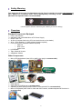
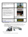
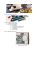
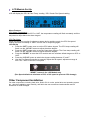
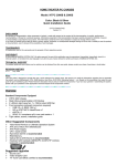
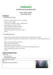
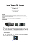
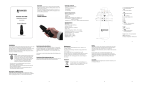
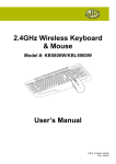
Home Theater PC Chassis
Model: HTPC 100 BA & SA
Color: Black & Silver
Quick Installation Guide
(U.S. & Canada Only)
Version 1.0
DISCLAIMER
No warranty or representation, either expressed or implied, is made with respect to the content of this documentation, its quality, performance, merchantability,
or fitness for a particular purpose. Information presented in this documentation has been carefully checked for reliability; however, no responsibility is
assumed for inaccuracies. The information contained in this documentation is subject to change without notice.
In no event will nMedia will be liable for direct, indirect, special, incidental, or consequential damages arising out of the use or inability to use this product or
documentation, even if advised of the possibility of such damages.
COPYRIGHT
© 2006 by NMEDIA SYSTEM, INC. All rights reserved. No part of this publication may be reproduced, transmitted, transcribed, stored in a retrieval system, or
translated into any language in any form by any means without the written permission of NMEDIA SYSTEM, INC.
TECHNICAL SUPPORT
If a problem arises with your system and no solution can be obtained from this user guide, please contact your place of purchase or local dealer.
REVISION HISTORY
V 2.0
October, 2006
Note:
This user guide is designed to provide the user a quick reference for chassis setup. We assume you need
the information regarding how to assemble the system, such as Motherboard, CPU, RAM Memory, Hard
Drive, DVD ROM, Operating System…, etc. Based on this assumption, we make this user guide of quick
installation guide. Please follow the description step by step to assemble the components. If you have any
question in assembling the system, you can contact your dealer or our technical support.
1
Safety Warning
Turn down the CPU Cooler Fan Speed through the Front Controller may create vital damage to
CPU. Adjust Fan Controller (CPU F.R.S.) appropriately according to the CPU instruction.
(Minimum Fan Speed at 2000 is recommended)
“RESET” button is for LCD Module only
(CPU Fan Speed is default to minimum speed of 1800 to prevent CPU damage)
Overview
Standard Components Equipped
¾ HTPC 100 Chassis
¾ nMEDIAPC MP-300 300W Micro ATX Power Supply
¾ 60mm Case Fan
¾ Air Duct (Constant fresh air to CPU and avoid hot air re-circulation)
¾ All-in-1 Card Reader (1 X USB onboard header required)
¾ Front Connectors (Onboard headers required)
o USB 2.0
o IEEE 1394
o Audio Ports
¾ LCD Module
¾ Tight Cables & Screws
¾ Installation Guides
Other Components
¾ Micro ATX Motherboard (Intel ViiV or AMD Live ready is recommended)
¾ CPU / Cooler (nMEDIAPC ICETANK or ICECONE is recommended)
¾
¾
¾
¾
¾
Hard Drive (SATA is recommended)
RAM Memory
Optical Drive (DVD Burner is recommended)
Operating System (Microsoft MCE 2005 or Vista with MCE is recommended)
Mouse & Keyboard (MCE 2005 or Vista with MCE remote, wireless keyboard & Receiver is
recommended)
2
For upgrades:
¾ Sound Card
¾ Video Graphic Card (Fanless model is recommended)
¾ TV Tuner Card (MCE certified is recommended)
Installation Flowchart (Basic Procedures)
Open Box Æ Read Installation Guide Æ Remove Top Cover Æ Remove Optical Drive
Bracket Æ Take Off Power Supply Æ Install Motherboard Æ Perform a chassis
quality check Æ Connect Cables Æ Install Hard Drive Æ Install CPU & Cooler Æ
Install DIMM Memory Module Æ Re-Install Power Supply Æ Install Optical Drive Æ
Connect Power Supply cables Æ Replace top cover
Installation Tools
Screw Driver / Screws
Tight Cables / Installation Guides
Tips:
1. After installing motherboard, perform a quality check on chassis parts before continuing. Connect
the power button to board, plug the PSU 20 or 24 pins and 4 pins cable temporarily, connect the
case fans power cord, connect the LCD PWR cord. Turn on the system. At this point, you
should be assure that the case and PSU are functioning well by checking if the fans running good,
front LCD turning on. Now, unplug everything and follow the instruction to continue your build.
2. Due to the limited height of the compact case, taking off the air duct may be necessary if you use
tall CPU heatsink, like NMEDIAPC ICETANK cooler.
3. If you are using the ICETANK or ICECONE CPU cooler, we recommend that you install the CPU
and Cooler onto the motherboard before you slot it in the case. This will smooth the cooler
installation with more space “outside” of the case.
4. Some DVD trays cover need to be removed in order to eject the tray smoothly without blocking by
the DVD flip down door.
5. When installing the DVD drive, adjust the DVD drive appropriately until your case eject button can
eject the tray smoothly, then mark down the position, and secure the DVD to the DVD rack with
screws.
6. Remember that installing power supply should always the last step when installing components.
7. Do not perform cable management until your system is fully configured. This will make the cable
management a better smooth procedure.
8. Do not install optional upgrade video card / TV tuner card / Sound card at once. Use everything on
board (video & sound) to configure system and install operation system. After then, install the
upgrades one by one and restart the system on every step to ensure component compatibility and
save times of troubleshooting when issue arises.
Installation
Step 1: Make more room to work on
1. Open the top cover
2. Remove the DVD bracket
3. Remove the Power Supply
3
Step 2: Connect cables
1. Install motherboard
2. Connect front panel / LCD cables
a) Connect Front USB 2.0, IEEE 1394 and Audio Connectors
b) Connect PWR Switch
c) Connect Card Reader internal USB cable
d) Connect LCD cables
e) See below table for more details
(Reference picture only)
Front USB 2.0, IEEE 1394 and Audio Connectors
See Motherboard User Manual for location and connection.
USB Port Color Codes:
IEEE 1394 Color Codes
Red = +5V
White = Data- (-D)
Green = Data+ (+D)
Black = Ground (GND)
Black -- Ground (GND)
Red -- +5V
Blue -- +TPB (TPB+)
White -- -TPB (TPB-)
Yellow -- +TPA (TPA+)
Green -- -TPA (TPA-)
USB Diagram
Audio Interface
Pin 1 (MIC IN) Red
Pin 2 (MIC GND) Black
Pin 5 & 6 (SR)
Pin 7 (Empty) White
Pin 8 & 9 (SL)
IEEE 1394 Diagram
Front Audio (AC 97) connection Tips:
First, find the MIC and GND pin, connect the MIC & GND connector fist, then, the SR connector must on the Pin
5 & 6, face the same label direction of the MIC & GND connector, plug the SR in, same to the SL on Pin 8 & 9.
Plug the white NC single pin connector to Pin 7.
Note: There is no HD Audio connector from this model yet.
Connect the Power Button “PWR” cable to the
motherboard front panel jumper
See Motherboard User Manual for location and
connection. And see above referenced picture.
4
Connect Card Reader USB cable
See Motherboard User Manual for onboard USB
port location and connection. And see above
referenced picture.
Connect LCD Cables (Some of these steps follow
after CPU & Cooler installation)
1. Place the case heat sensor anywhere that you want
2. Use the orange tape in the accessory bag to tape
the CPU heat sensor to the CPU heatsink
3. Connect the CPU heatsink fan to the LCD “CPU
Fan” adapter, if your motherboard has the auto fan
speed control function (base on CPU temp); plug
the extension cord to the motherboard fan
connector. In this case, the LCD will only display
fan speed, no fan speed control will be available via
the front knob.
4. Connect the “PWR” LCD power cord to the power
supply like connecting the case fan
<<Periodically check sensor head placement is
recommended to ensure accurate CPU
Temperature Reading>>
LCD Replacement
If you wish to replace the hard coded LCD with
programmable LCD, please check our website
for more details:
http://www.nmediapc.com/support_LCD.htm
Step 3: Install Hard Drive
1.
2.
There are two 3.5” bays available for this model besides the third one which
occupied by the card reader. One next to the card reader and one under the optical
drive rack.
SATA hard drive is preferred to place under the optical drive since the cable is
closer to the onboard SATA ports most of the time.
Step 4: Install CPU and Cooler
Follow your motherboard user manual to avoid damages
5
Step 5: Install memory module
Step 6: Install the power supply
1. Install the power supply
2. Connect power cables
a) to hard drive
b) to motherbaord 20/24 pin main
c) to motherborad 4 pin +12V
d) to LCD PWR
e) to optical drive
Step 7: Install the optical drive
(Reference picture only)
6
LCD Module Set Up
LCD will display the CPU & Case Temp. reading / CPU Cooler Fan Speed reading
Alarm Features
CPU Alarm Temperature
When CPU temperature hits 65ºC or 149F, the temperature reading will flash constantly until the
temperature drops below the alarm degree.
CPU Fan Alarm
When the fan stops running for whatever reason during working mode, the CPU fan speed
reading will flash constantly in “0000” until the fan is re-spinning again.
LCD Set Up
1. Press the “SET” button once to set the CPU alarm degree. The CPU temp reading will
flash; use the “C/F UP” button to adjust the alarm degree.
2. Press the “SET” button twice to set the Case alarm degree. The Case temp reading will
flash; use the “C/F UP” button to adjust the alarm degree.
3. Press the “RESET” to reset the LCD module and turn all alarm default degree to 65ºC or
149F.
4. Press the “C/F UP” button to switch the degree reading between ºC and F.
5. Use the Fan Speed Controller to manually adjust the fan speed, adjustment range is
from 70% -100% of the fan’s full speed.
“RESET” button is for LCD Module only
(Fan Speed defaults to minimum of 70% of full speed to prevent CPU damage)
Other Component Installation
For other components, including hard drive; RAM; CPU & cooler; optical drive and operating system
etc., plan the installation steps carefully, and follow the user manual and motherboard manual
instruction to avoid damages.
7
References
Technical Support
NMEDIA SYSTEM, INC
[email protected]
http://www.nmediapc.com/support.htm
Safety Instructions
Always read the step by step installation to protect your components
Keep the user guide for future reference
Keep away from humidity, liquid and temperature above 60c (140 f) environment
Make sure the voltage of the power supply and adjust properly 110/230V
Always unplug the power cord before inserting any add-on devices
Get the system checked by service personnel if below happens:
• The power cable is damage
• Liquid has penetrated into the system
• Dropped and damaged
RMA Return Policy
•
•
•
All accessories and cables must be returned as they were shipped
Carefully re-packaging is needed to avoid shipping damages
All warranties are subject to properly uses. Any human power damages return may be
rejected according to warranty terms and conditions
Copyright © 2006 NMEDIA SYSTEM, INC. All Right Reserved.
8