1
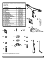
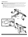
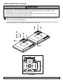
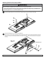
Installation and Assembly:
Dual-Screen Desktop Mount for 10" to 20" LCD Monitors
Models: LCT-202
Max Load Capacity: 25 lb (11.3 kg) per arm
3215 W. North Ave. • Melrose Park, IL 60160 • (800) 729-0307 or (708) 865-8870 • Fax: (708) 865-2941 • www.peerlessmounts.com
ISSUED: 07-31-09 SHEET #: 090-9183-2 10-29-09
Note: Read entire instruction sheet before you start installation and assembly.
WARNING
• Do not begin to install your Peerless product until you have read and understood the instructions and warnings
contained in this Installation Sheet. If you have any questions regarding any of the instructions or warnings, for US
customers please call Peerless customer care at 1-800-865-2112, for all international customers, please contact
your local distributor.
• This product should only be installed by someone of good mechanical aptitude, has experience with basic building
construction, and fully understands these instructions.
• Make sure that the supporting surface will safely support the combined load of the equipment and all attached
hardware and components.
• Never exceed the Maximum Load Capacity. See page one.
• Always use an assistant or mechanical lifting equipment to safely lift and position equipment.
• Tighten screws firmly, but do not overtighten. Overtightening can damage the items, greatly reducing their holding
power.
• This product is intended for indoor use only. Use of this product outdoors could lead to product failure and personal
injury.
Table of Contents
Parts List.................................................................................................................................................................................3
Cable Management.................................................................................................................................................................4
Attaching VESA Plates to Display...........................................................................................................................................5
Attaching Display to Dual Arm Assembly................................................................................................................................6
Attaching Dual Arm Assembly to Base....................................................................................................................................7
2 of 7
Visit the Peerless Web Site at www.peerlessmounts.com
ISSUED: 07-31-09 SHEET #: 090-9183-2 10-29-09
For customer care call 1-800-729-0307 or 708-865-8870.
Before you begin, make sure all parts shown are included with
your product.
Parts list
A
B
C
D
e
F
G
H
I
J
K
L
M
N
o
P
Q
R
Description
Dual arm column
VESA plate
Column cover*
Base
M6 flat washer
M6 lock washer
M6 hex head screw
adhesive cable anchors
#8 phillips self-tapping screw*
M10 flat washer*
M10 split lock washer*
M10 wingnut*
rubber bumpers
M4 flat washer
M4 lock washer
M4 pan phillips head screw
cable ties
5 mm allen wrench
Qty.
1
2
1
1
2
2
2
2
1
1
1
1
3
8
8
8
2
1
Part #
A
AD19-T2-00
VCUP-00-00
CLMC-05-00
BASE-02-00
HWWA-M6-01
HWLC-M6-01
HSHX-M6-25
HTWA-01-00
HSST-I8-75
HWWA-10-01
HWLC-10-01
HNUT-10-01
HRBS-20-01
HWWA-M4-01
HWLC-M4-01
HSPP-M4-16
HTWR-01-00
TAKY-05-01
B
D
*item attached to dual arm column (A)
H
I
E
C
M
J
N
K
O
F
Q
R
P
L
G
Parts may appear slightly different than illustrated.
3 of 7
Visit the Peerless Web Site at www.peerlessmounts.com
ISSUED: 07-31-09 SHEET #: 090-9183-2 10-29-09
For customer care call 1-800-729-0307 or 708-865-8870.
Cable Management
1
Remove #8 self-tapping screw (I) using a phillips screw driver to unattach column cover (C) from dual arm column
(A). Insert cables into cavity of the dual arm column (A) as shown in figure 1.1 and reattach column cover (C) to
back of dual arm column (A) using #8 self-tapping screw (I).
NOTE: Be sure connectors are in their proper orientation. Allow enough cable slack to connect to display.
NOTE: Be sure all cables are free from interference and do not pinch power cables with column cover or fastener
as shown in detail 1.
Remove adhesive backing from cable anchors (H) and position onto back of dual arm column (A) as shown in
figure 1.2. Secure cables to arms using cable ties (Q).
I
C
CAVITY
A
C
I
CABLES
fig 1.1
A
H
fig 1.2
DETAIL 1
Q
CABLES
4 of 7
Visit the Peerless Web Site at www.peerlessmounts.com
ISSUED: 07-31-09 SHEET #: 090-9183-2 10-29-09
For customer care call 1-800-729-0307 or 708-865-8870.
Attaching VESA Plates to Display
WARNING
• Tighten screws so VESA plates are firmly attached. Do not tighten with excessive force. Overtightening can cause
stress damage to screws, greatly reducing their holding power and possibly causing screw heads to become
detached. Tighten to 40 in. • lb (4.5 N.M.) maximum torque.
• If screws don't get three complete turns in the screen inserts or if screws bottom out and bracket is still not tightly
secured, damage may occur to screen or product may fail.
2
To prevent scratching the display, set a cloth on a flat, level surface that will support the weight of the screen. Place
display face side down. If display has knobs on the back, remove them to allow the VESA plates to be attached.
Place VESA plates (B) on back of display.
Choose hole pattern as shown in detail 2. Attach VESA plates (B) to display using four M4 phillips screws (P), four
M4 lock washers (O), and four M4 flat washers (N) as shown in figure 2.1.
P
O
N
B
fig 2.1
DETAIL 2
5 of 7
Visit the Peerless Web Site at www.peerlessmounts.com
ISSUED: 07-31-09 SHEET #: 090-9183-2 10-29-09
For customer care call 1-800-729-0307 or 708-865-8870.
Attaching Dual Arm Assembly to Base
WARNING
• Be sure display is unplugged from any electrical outlet while assembling dual stand.
• Tighten screws so adapter brackets are firmly attached. Do not tighten with excessive force. Overtightening can
cause stress damage to screws, greatly reducing their holding power and possibly causing screw heads to become
detached. Tighten to 40 in. • lb (4.5 N.M.) maximum torque.
3
Attach VESA plates to dual arm column (A) using one M6 hex head screw (G), one M6 split lock washer (F) and
one M6 flat washer (E) per arm as shown below. Tighten fasteners using 5 mm allen wrench (R).
G
F
E
A
4
Unscrew M10 fasteners (J, K, and L) from threaded rod.
Attach dual arm column (A) to base (D) by hand threading M10 washer (J), M10 split lockwasher (K), and M10
wingnut (L) through arm assembly threaded rod as shown in figure 4.1. Ensure that all fasteners are tightened
securely.
fig 4.1
THREADED ROD
J
K
L
6 of 7
Visit the Peerless Web Site at www.peerlessmounts.com
ISSUED: 07-31-09 SHEET #: 090-9183-2 10-29-09
For customer care call 1-800-729-0307 or 708-865-8870.
WARNING
• Use two displays with this mount. Product may fail and damage property if not installed correctly.
5
Apply rubber bumpers (M) to bottom of base as shown in figure 5.1.
Carefully lift the full assembly to its upright position as shown in figure 5.2.
NOTE: Be sure assembly rests on a flat, level surface to prevent the displays from tipping.
M
fig 5.1
fig 5.2
NOTE: Leave a small gap between the displays to allow for horizontal pivot adjustment as shown below.
7 of 7
Visit the Peerless Web Site at www.peerlessmounts.com
ISSUED: 07-31-09 SHEET #: 090-9183-2 10-29-09
For customer care call 1-800-729-0307 or 708-865-8870.
© 2009, Peerless Industries, Inc. All rights reserved.
All other brand and product names are trademarks or registered trademarks of their respective owners.


![Revco CxF - User Manual [ES]](http://vs1.manualzilla.com/store/data/006249556_1-016d09cce2c1c59e6584f151fcdbd792-150x150.png)