1
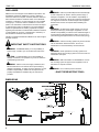
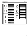
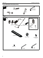
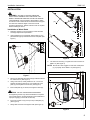
INSTALLATION INSTRUCTIONS
Height-Adjustable Dual Arm with Keyboard Tray
Spanish Product Description
German Product Description
Portuguese Product Description
Italian Product Description
Dutch Product Description
French Product Description
KWK-110
KWK-110
Installation Instructions
DISCLAIMER
Milestone AV Technologies and its affiliated corporations and
subsidiaries (collectively "Milestone"), intend to make this
manual accurate and complete. However, Milestone makes no
claim that the information contained herein covers all details,
conditions or variations, nor does it provide for every possible
contingency in connection with the installation or use of this
product. The information contained in this document is subject
to change without notice or obligation of any kind. Milestone
makes no representation of warranty, expressed or implied,
regarding the information contained herein. Milestone assumes
no responsibility for accuracy, completeness or sufficiency of
the information contained in this document.
Chief® is a registered trademark of Milestone AV Technologies.
All rights reserved.
WARNING: Failure to provide adequate structural strength
for this component can result in serious personal injury or
damage to equipment! It is the installer’s responsibility to
make sure the structure to which this component is attached
can support five times the combined weight of all equipment.
Reinforce the structure as required before installing the
component.
WARNING: Exceeding the weight capacity can result in
serious personal injury or damage to equipment! It is the
installer’s responsibility to make sure the combined weight of
all components located between the KWK-110 mount up to
(and including) the keyboard does not exceed 10 lbs (4.5 kg).
WARNING: Use this mounting system only for its intended
IMPORTANT SAFETY INSTRUCTIONS
use as described in these instructions. Do not use
attachments not recommended by the manufacturer.
WARNING: A WARNING alerts you to the possibility of
serious injury or death if you do not follow the instructions.
WARNING: Never operate this mounting system if it is
damaged. Return the mounting system to a service center for
examination and repair.
CAUTION: A CAUTION alerts you to the possibility of
damage or destruction of equipment if you do not follow the
corresponding instructions.
WARNING: Failure to read, thoroughly understand, and
follow all instructions can result in serious personal injury,
damage to equipment, or voiding of factory warranty! It is the
installer’s responsibility to make sure all components are
properly assembled and installed using the instructions
provided.
WARNING: RISK OF INJURY TO PERSONS! Do not use
this mounting system to support video equipment such as
televisions or computer monitors.
WARNING: Do not use this product outdoors.
--SAVE THESE INSTRUCTIONS--
DIMENSIONS
6.50
WRISTPAD
(REMOVABLE)
18.75
EXTENDED
COLLAPSED
29.14
6.15
2
KEYBOARD TRAY ANGLE
ADJUSTABLE 15
Installation Instructions
KWK-110
LEGEND
Tighten Fastener
Pencil Mark
Apretar elemento de fijación
Marcar con lápiz
Befestigungsteil festziehen
Stiftmarkierung
Apertar fixador
Marcar com lápis
Serrare il fissaggio
Segno a matita
Bevestiging vastdraaien
Potloodmerkteken
Serrez les fixations
Marquage au crayon
Loosen Fastener
Drill Hole
Aflojar elemento de fijación
Perforar
Befestigungsteil lösen
Bohrloch
Desapertar fixador
Fazer furo
Allentare il fissaggio
Praticare un foro
Bevestiging losdraaien
Gat boren
Desserrez les fixations
Percez un trou
Phillips Screwdriver
Open-Ended Wrench
Destornillador Phillips
Llave de boca
Kreuzschlitzschraubendreher
Gabelschlüssel
Chave de fendas Phillips
Chave de bocas
Cacciavite a stella
Chiave a punte aperte
Kruiskopschroevendraaier
Steeksleutel
Tournevis à pointe cruciforme
Clé à fourche
Hex-Head Wrench
Llave de cabeza hexagonal
Sechskantschlüssel
Chave de cabeça sextavada
Chiave esagonale
Zeskantsleutel
Clé à tête hexagonale
3
KWK-110
Installation Instructions
TOOLS REQUIRED FOR INSTALLATION
3/16" (included)
5/32" (included)
#2
7/16"
1/8"
PARTS
Mounting Kit
A (1)
[KWK-110]
C (1)
[Wall plate]
B (1)
[Cable management cover]
D (2)
1/4 x 2 1/2"
E (2)
1/4"
F (1)
[Gel wrist pad]
G (1)
[Mouse holder]
H (6)
[Hook and loop
fastener]
J (2)
#8-32 x 3/8"
K (1)
3/16"
4
L (1)
5/32"
Installation Instructions
KWK-110
INSTALLATION
WARNING: FAILURE TO PROVIDE ADEQUATE
STRUCTURAL STRENGTH FOR THIS MOUNT CAN
RESULT IN SERIOUS PERSONAL INJURY OR DAMAGE
TO EQUIPMENT! It is the installer’s responsibility to make
sure the structure to which this mount is attached can support
five times the combined weight of the mount and all
equipment attached to it. Reinforce the structure as required
before installing the mount.
(A)
6
Installation to Wood Studs
1.
Determine location for mount keeping in mind extension
and height adjustment requirements.
2.
Using wall plate (C) as a template, mark location for two
pilot holes through top and bottom holes of wall plate. (See
Figure 1)
(C)
2
4
(D) x 2
3
(E) x 2
7
Figure 2
8.
Use 5/32" hex wrench (L) to tighten set screw in bottom of
KWK-110. (See Figure 3)
NOTE: Ensure set screw engages on back side of wall plate
(C) to properly secure KWK-110. (See Figure 3)
(C)
Figure 1
3.
Drill two 1/8" diameter pilot holes through marked locations
into wall structure. (See Figure 1)
4.
Using 7/16" wrench, loosely install two 1/4" x 2 1/2" hex
head lag screws (D) through two 1/4" washers (E), wall
plate (C), and drywall into wood stud. (See Figure 1)
5.
(C)
Ensure wall plate (C) is vertical, then tighten screws (D).
(A)
CAUTION: DO NOT OVERTIGHTEN FASTENERS!
Overtightening screws may cause wall bracket to compress
into soft wall surface, resulting in difficult mount installation or
improper engaging of set screw in later step.
6.
Insert top of KWK-110 (A) over lip at top of wall plate (C).
(See Figure 2)
7.
Swing KWK-110 down flush against wall. (See Figure 2)
8
Set
Screw
Figure 3
5
KWK-110
Installation Instructions
Keyboard and Wrist Pad Installation
CABLE MANAGEMENT
1.
Remove paper from adhesive backing on one side of hook
and loop fasteners (H).
1.
2.
Place hook and loop fasteners (H) on bottom of the
keyboard (not included) and bottom of wrist pad (F)
approximately as shown. (See Figure 4)
NOTE: If necessary, cable management bracket attach screws
NOTE: Place fasteners only on flat surfaces of the keyboard to
ensure that fasteners stick to keyboard surface.
3.
Remove paper from the adhesive backing on the other side
of the hook and loop fasteners (H).
4.
Firmly place keyboard on keyboard tray making sure to
leave room for the wrist pad, if necessary. (See Figure 4)
5.
Firmly place wrist pad (F) on keyboard try in front of the
keyboard. (See Figure 4)
(H) x 3
Thread keyboard cable through one of two cable
management holes along back edge of keyboard tray. (See
Figure 5)
may be loosened using 3/16" hex key (K).
2.
Open cable management bracket on upper portion of mount
arm by sliding it towards edge of arm. (See Figure 6)
Attach
screws
Keyboard (not included)
OPEN position
CLOSED position
View from bottom
Figure 6
(F)
CAUTION: Ensure that adequate cable slack is available
(H) x 3
for movement of keyboard and mouse. Do not pinch cables
when closing cable management bracket.
3.
Carefully insert cables into bracket. (See Figure 7)
(A)
Figure 4
Mouse Holder Installation
1.
Remove paper from adhesive on mouse holder (G).
2.
Place mouse holder (G) on wall at desired location. (See
Figure 5)
Cable path
(typical)
Cable management holes
Cable management
bracket (OPEN position)
Figure 7
4.
(G)
Close cable management bracket by sliding it back towards
centerline of arm.
NOTE: If necessary, cable management bracket attach screws
may be tightened using 3/16" hex key (K).
(A)
Figure 5
6
Installation Instructions
KWK-110
5.
Carefully insert cables into cavity located in lower portion of
mount arm. (See Figure 8)
6.
Install cable management cover (B) using two #8-32 x 3/8"
Phillips flat head screws (J). (See Figure 8)
3
Height adjustment
screw
Cable path
(typical)
Height
adjustable
arm
(B)
(J) x 2
6
Figure 8
ADJUSTMENTS
Figure 10
Swing Arm Pivot/Swing Adjustment
1.
4.
Slightly loosen or tighten the adjustment screw(s) as
necessary, using the 3/16" hex key (K). (See Figure 9)
5
Pivot/Swing adjustment screws
1
Adjust tray tension using a 7/16" wrench and a 5/32" (L) hex
key. (See Figure 11)
Tilt angle
adjustment knob
4
2
4
Adjustable
mouse trays
4
2
Figure 9
Mouse Tray Adjustment
2.
Mouse trays slide open and closed on both sides of the tray
for use by both right- and left-handed users. (See Figure 9)
Height Adjustment
3.
Slightly loosen or tighten the height adjustment screw as
necessary, using the 5/32" hex key (L). (See Figure 10)
•
•
If keyboard tray lowers on its own, rotate
adjustment screw counterclockwise (towards
the "+" symbol).
If keyboard tray rises on its own, rotate
adjustment screw clockwise (towards the "-"
symbol).
Figure 11
5.
Adjust the tilt angle adjustment knob as necessary to set tilt
angle of keyboard tray. (See Figure 11)
NOTE: It may be necessary to raise or lower the height
adjustable arm to expose the adjustment screw.
7
KWK-110
Installation Instructions
USA/International
Europe
Chief Manufacturing, a products division
of Milestone AV Technologies
8800-002343 Rev00
2013 Milestone AV Technologies, a
Duchossois Group Company
www.chiefmfg.com
04/13
Asia Pacific
A
P
F
A
P
F
A
6436 City West Parkway, Eden Prairie, MN 55344
800.582.6480 / 952.225.6000
877.894.6918 / 952.894.6918
Franklinstraat 14, 6003 DK Weert, Netherlands
+31 (0) 495 580 852
+31 (0) 495 580 845
Office No. 1 on 12/F, Shatin Galleria
18-24 Shan Mei Street
Fotan, Shatin, Hong Kong
P 852 2145 4099
F 852 2145 4477