1
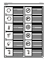
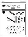
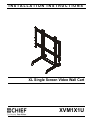
INSTALLATION INSTRUCTIONS
Instrucciones de instalación
Installationsanleitung
Instruções de Instalação
Istruzioni di installazione
Installatie-instructies
Instructions d´installation
XL Single Screen Video Wall Cart
Spanish Product Description
German Product Description
Portuguese Product Description
Italian Product Description
Dutch Product Description
French Product Description
XVM1X1U
XVM1X1U
DISCLAIMER
Milestone AV Technologies and its affiliated corporations and
subsidiaries (collectively "Milestone"), intend to make this
manual accurate and complete. However, Milestone makes no
claim that the information contained herein covers all details,
conditions or variations, nor does it provide for every possible
contingency in connection with the installation or use of this
product. The information contained in this document is subject
to change without notice or obligation of any kind. Milestone
makes no representation of warranty, expressed or implied,
regarding the information contained herein. Milestone assumes
no responsibility for accuracy, completeness or sufficiency of
the information contained in this document.
Chief® is a registered trademark of Milestone AV Technologies.
All rights reserved.
Installation Instructions
properly assembled and installed using the instructions
provided.
WARNING: Failure to provide adequate structural strength
for this component can result in serious personal injury or
damage to equipment! It is the installer’s responsibility to
make sure the structure to which this component is attached
can support five times the combined weight of all equipment.
Reinforce the structure as required before installing the
component.
WARNING: Exceeding the weight capacity can result in
serious personal injury or damage to equipment! It is the
installer’s responsibility to make sure the combined weight of
display and attached accessories mounted to the XVM1X1U
mount does not exceed 500 lbs (226.8 kg).
IMPORTANT SAFETY INSTRUCTIONS
WARNING: Use this mounting system only for its intended
WARNING: A WARNING alerts you to the possibility of
serious injury or death if you do not follow the instructions.
CAUTION: A CAUTION alerts you to the possibility of
damage or destruction of equipment if you do not follow the
corresponding instructions.
WARNING: Failure to read, thoroughly understand, and
follow all instructions can result in serious personal injury,
damage to equipment, or voiding of factory warranty! It is the
installer’s responsibility to make sure all components are
DIMENSIONS
36.00
914.4
2
use as described in these instructions. Do not use
attachments not recommended by the manufacturer.
WARNING: Never operate this mounting system if it is
damaged. Return the mounting system to a service center for
examination and repair.
WARNING: Do not use this product outdoors.
--SAVE THESE INSTRUCTIONS--
Installation Instructions
XVM1X1U
LEGEND
Tighten Fastener
Pencil Mark
Apretar elemento de fijación
Marcar con lápiz
Befestigungsteil festziehen
Stiftmarkierung
Apertar fixador
Marcar com lápis
Serrare il fissaggio
Segno a matita
Bevestiging vastdraaien
Potloodmerkteken
Serrez les fixations
Marquage au crayon
Loosen Fastener
Drill Hole
Aflojar elemento de fijación
Perforar
Befestigungsteil lösen
Bohrloch
Desapertar fixador
Fazer furo
Allentare il fissaggio
Praticare un foro
Bevestiging losdraaien
Gat boren
Desserrez les fixations
Percez un trou
Phillips Screwdriver
Adjust
Destornillador Phillips
Ajustar
Kreuzschlitzschraubendreher
Einstellen
Chave de fendas Phillips
Ajustar
Cacciavite a stella
Regolare
Kruiskopschroevendraaier
Afstellen
Tournevis à pointe cruciforme
Ajuster
Open-Ended Wrench
Remove
Llave de boca
Quitar
Gabelschlüssel
Entfernen
Chave de bocas
Remover
Chiave a punte aperte
Rimuovere
Steeksleutel
Verwijderen
Clé à fourche
Retirez
By Hand
Optional
A mano
Opcional
Von Hand
Optional
Com a mão
Opcional
A mano
Opzionale
Met de hand
Optie
À la main
En option
Hex-Head Wrench
Security Wrench
Llave de cabeza hexagonal
Llave de seguridad
Sechskantschlüssel
Sicherheitsschlüssel
Chave de cabeça sextavada
Chave de segurança
Chiave esagonale
Chiave di sicurezza
Zeskantsleutel
Veiligheidssleutel
Clé à tête hexagonale
Clé de sécurité
3
XVM1X1U
Installation Instructions
TOOLS REQUIRED FOR INSTALLATION
#2
1/2" (12.7mm)
3/16" (included)
M14 (included)
PARTS
A (1)
[base cross bar]
C (1)
[right leg]
B (1)
[left leg]
F (2)
[column cap]
E (2)
[cart array column]
J (2)
[end bracket]
G (4)
[clamp bracket]
D (2)
[mounting rail]
K (1)
3/16" hex bit
H (4)
[quick connect base]
N (4)
M (8)
5/16-18
x 4 1/2"
5/16-18 x 2 1/2"
P (4)
5/16-18 x 5"
U (4)
5/16-18 x 1"
V (8)
5/16-18"
T (8)
5/16-18 x 1/2"
Y (4)
M16x90mm
4
Z (4)
5/16-18 x 2 1/2"
Q (32)
5/16-18 x 3/4"
R (24)
5/16"
X (4)
[snap cover]
W (1)
3/16"
AA (4)
[spacer]
L (2)
[upright assembly]
BB (1)
M14
Installation Instructions
XVM1X1U
Assembly And Installation
Cart Assembly
1.
Lay two cart array columns (E) down on a flat surface.
2.
Use eight 5/16-18 x 2 1/2" button head cap screws (M) and
eight 5/16" washers (R) to connect cross bar (A) to columns
(E). (See Figure 1)
4
(P) x 4
(B)
(C)
3
(T) x 4
(R) x 4
(J) x 2
(E) x 2
4
(V) x 4
(A)
Figure 2
Rails Installation
1.
(R) x 8
2
Place clamp brackets (P) on columns with the top hole on
the brackets lined up with the top holes on the columns.
(See Figure 3)
(rear view)
(M) x 8
(V)
2
1
Figure 1
3.
Use four 5/16-18 x 1/2" button head cap screws (T) to attach
two end brackets (J) to cross bar (A). (See Figure 1)
4.
Use four 5/16-18 x 5" button head cap screws (P), four 5/16"
washers (R) and four 5/16-18" lock nuts (V) to secure right
and left legs (B and C) to cross bar (A). (See Figure 2)
(N)
2
1
NOTE: To ensure right and left legs (B and C) are assembled
on the appropriate side, make sure the smooth side of
the legs are to the outside when assembling to cross
bar (A).
5.
Stand cart up on its wheels.
6.
Proceed to Install Rails Section.
4
(V)
(R) x 2
3
4
(N)
3
5 holes
from bottom
(R) x 2
Figure 3
2.
Use 5/16-18 x 4 1/2" button head cap screw (N), two 5/16"
washers (R) and 5/16-18" lock nut (V) to secure each clamp
bracket (G) to column. (See Figure 3)
5
XVM1X1U
Installation Instructions
Place clamp brackets (G) on columns with the top hole on
the brackets lined up with the fifth holes from the bottom of
the columns. (See Figure 3)
8.
Install two 5/16-18 x 3/4" button head flange screws (Q) into
the lower holes on each quick connect base (H) to secure
rails (D) to quick connect bases. (See Figure 6)
IMPORTANT ! : The upper and lower clamp brackets (G)
must be installed exactly 36" apart in order for the
uprights to fit correctly.
9.
Tighten all 5/16-18 x 3/4" button head flange screws (Q).
3.
4.
Use 5/16-18 x 4 1/2" button head cap screw (N), two 5/16"
washers (R) and 5/16-18" lock nut (V) to secure each clamp
bracket (G) to column. (See Figure 3)
5.
Use four 5/16-18 x 3/4" button head flange screws (Q) to
secure each attached clamp bracket (G) to a quick connect
base (H). (See Figure 4)
5
8
(Q) x 2
(H)
(Q) x 4
Figure 6
Display Installation
1.
Place display face down on a soft, non-abrasive surface.
NOTE: For best access, route display cables through columns
(G)
prior to display installation. See Cable Management
section for details.
CAUTION: Using screws of improper size may damage
your display! Only use hardware provided to mount display.
2.
Figure 4
6.
Use M16 x 90mm socket head cap screws (Y) and spacers
(AA) to connect interface brackets (L) to back of display.
(See Figure 7)
Install two 5/16-18 x 3/4" button head flange screws (Q) into
the top holes on each quick connect base (H). (See Figure
5)
2
6
(Y) x 4
(Q) x 2
(L) x 2
7
(D) x 2
(H)
(AA) x 4
Figure 5
7.
6
Hang rails (D) into screws installed in previous step to quick
connect bases (H). (See Figure 5)
Figure 7
Installation Instructions
XVM1X1U
3
CENTER DISPLAY
ON CART TO
AVOID TIPPING!
(D) x 2
4
(L) x 2
CENTER DISPLAY
ON CART TO
AVOID TIPPING!
3
3
4
4
3
4
Figure 8
WARNING: Exceeding the weight capacity can result in
serious personal injury or damage to equipment! It is the
installer’s responsibility to make sure the combined weight of
display and attached accessories mounted to the XVM1X1U
mount does not exceed 500 lbs (226.8 kg).
5
(Z) x 4
WARNING: DISPLAY MAY WEIGH IN EXCESS OF 40
LBS! Always use two people and proper lifting techniques
when installing or positioning display on cart!
3.
Hang interface brackets (L) to center of mounting rails (D).
(See Figure 8)
WARNING: FAILING TO CENTER DISPLAY ON
XVM1X1U CART MAY CAUSE THE MOUNT TO TIP OVER
WHICH COULD RESULT IN SERIOUS PERSONAL INJURY
OR DAMAGE TO EQUIPMENT! Always install display onto
the center of the cart!
4.
Lift locking brackets on interface brackets (L) up to the back
of mounting rails (D). (See Figure 8)
5.
Use four 5/16-18 x 2 1/2" button head cap screws (Z) to
secure interface brackets (L) to rails. (See Figure 9)
Figure 9
7
XVM1X1U
Installation Instructions
2.
Column Cap Installation
1.
Use four 5/16-18 x 1/2" button head cap screws (T) to install
each column cap (F) to each column. (See Figure 10)
(T) x 4
1
For any cable management holes that are not used, snap
covers (X) may be used to cover holes as desired. (See
Figure 12)
(display not shown
for clarity)
(F)
(X)
2
Figure 10
Cable Management
1.
Route cables from displays through nearest holes on front
of columns and out through back cable management hole.
(See Figure 11)
NOTE: For best access, route display cables through columns
prior to display installation. See Cable Management
section for details.
(display not shown for clarity)
1
1
1
1
Figure 11
8
Figure 12
Installation Instructions
XVM1X1U
9
XVM1X1U
10
Installation Instructions
Installation Instructions
XVM1X1U
11
XVM1X1U
Installation Instructions
USA/International
Europe
Chief Manufacturing, a products division
of Milestone AV Technologies
8800-002255 Rev01
2012 Milestone AV Technologies, a
Duchossois Group Company
www.chiefmfg.com
11/12
Asia Pacific
A
P
F
A
P
F
A
6436 City West Parkway, Eden Prairie, MN 55344
800.582.6480 / 952.225.6000
877.894.6918 / 952.894.6918
Franklinstraat 14, 6003 DK Weert, Netherlands
+31 (0) 495 580 852
+31 (0) 495 580 845
Office No. 1 on 12/F, Shatin Galleria
18-24 Shan Mei Street
Fotan, Shatin, Hong Kong
P 852 2145 4099
F 852 2145 4477