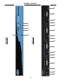
1
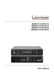
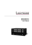
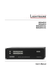
®
DVI DL to
Converter
EXT-DVIDL-2-HDMIR
User Manual
www.gefen.com
.
ASKING FOR ASSISTANCE
Technical Support:
Telephone
(818) 772-9100
(800) 545-6900
Fax
(818) 772-9120
Technical Support Hours:
8:00 AM to 5:00 PM Monday through Friday PST
Write To:
Gefen Inc.
c/o Customer Service
20600 Nordhoff St
Chatsworth, CA 91311
www.gefen.com
[email protected]
Notice
Gefen Inc. reserves the right to make changes in the hardware, packaging and
any accompanying documentation without prior written notice.
DVI DL to HDMI Converter is a trademark of Gefen Inc.
© 2010 Gefen Inc., All Rights Reserved
All trademarks are the property of their respective owners
Rev A4
CONTENTS
1
Introduction
2
Operation Notes
3
Features
4
Panel Layout
5
Panel Descriptions
6
Connecting And Operating The DVI Dl To HDMI Converter
7
Specifications
8
Warranty
INTRODUCTION
Congratulations on your purchase of the DVI DL to HDMI Converter. Your
complete satisfaction is very important to us.
Gefen
Gefen delivers innovative, progressive computer and electronics add-on solutions
that harness integration, extension, distribution and conversion technologies.
Gefen’s reliable, plug-and-play products supplement cross-platform computer
systems, professional audio/video environments and HDTV systems of all sizes
with hard-working solutions that are easy to implement and simple to operate.
1
OPERATION NOTES
READ THESE NOTES BEFORE INSTALLING OR
OPERATING THE DVI DL TO HDMI CONVERTER
•
The DVI DL to HDMI Converter has 2 switches per input (4 inputs are
provided). The Master Switch will allow the use of the 10-bit and 12-bit color
modes. Once the main switch is in the ON position, 10-bit or 12-bit color
modes can be selected. Disable the Master Switch to turn off the extended
color modes and enable 8-bit color depth.
2
FEATURES
Features
•
Converts up to 4 proprietary DVI-DL signals (supporting 12bit color) to HDMI.
•
Selector switch that will enable/disable Deep Color
•
10-bit and 12-bit Deep Color modes
•
LED link indicators to ensure that all connections are active
Package Includes
(1) DVI DL to HDMI Converter Unit
(4) 6 Foot DVI DL Cable (M-M)
(1) 24V DC Power Supply (2.5A each)
(1) Pair of Rack Ears
3
4
5
6
7
4
5
6
7
4
4
5
Back Panel
Front Panel
6
2
1
7
3
3
4
3
5
3
6
7
8
PANEL LAYOUT
PANEL DESCRIPTIONS
1
Power LED Indicator
This input indicator will become active once the included 24V DC power adapter
has been properly connected to a power source.
2
Reset Button
This button will reset the unit and force all input/outputs to re-initialize.
3
Active Link LED Indicator
This LED indicator will activate once a link has been detected from the source
device to the output device.
4
10-Bit/12-Bit Selector Switch
This switch will set either the 10-bit or 12-bit color modes. This switch is only
active when the Main Switch is in the ON position.
5
Master Switch
This switch will enable/disable the use of the extended color modes switch;
10-Bit/12-Bit Selector Switch
6
HDMI Output
This port will accept a single HDMI capable output device via an HDMI type A
connector.
7
DVI-DL Input
This port will accept a single DVI-DL (proprietary signal) input device via a DVI-I
type connector.
8
24V DC Power Input
This input will accept power from the included 24V DC power supply. Connect
the power supply to the unit and an available power source.
5
CONNECTING AND OPERATING THE DVI DL TO HDMI CONVERTER
How to Connect the DVI DL to HDMI Converter
1.
Connect up to 4 DVI dual link source devices to the DVI DL to HDMI
Converter’s DVI inputs. 4 DVI DL cables are supplied.
2.
Connect up to 4 HDMI capable displays to the DVI DL to HDMI Converter’s
HDMI outputs. 4 HDMI cables are supplied.
3.
Connect the supplied 24V DC power supply to the DVI DL to HDMI
Converter. Plug the power cable into a power source.
How to Operate the DVI DL to HDMI Converter
Once all input and output devices are connected and power has been applied,
the DVI DL to HDMI Converter should be on. Once the source devices and
output devices are properly linked, the front panel LED’s should become active.
The rear panel carries sets of switches to enable 10-bit and 12-bit deep color.
A Master Switch must be enabled per input to activate these extended color
modes. When the master switch is in the OFF position, 8-bit color is enabled.
To use 10-bit and 12-bit color modes, please set the Master Switch to the
ON position. This must be done for each input that will use the extended color
modes.
Once the Master Switch is set to ON, use the 10-bit/12-bit selector switch to
enable the desired color mode.
Changes are immediate and do not require a system reset. If a reset is required,
please press the RESET button located on the front panel.
6
SPECIFICATIONS
Video Amplifier Bandwidth ....................................................................... 225 MHz
Maximum Resolution ......................................... 1080p (HDTV) / 1920x1200 (PC)
Maximum Color Depth ......................................................................... 12-bit 4:4:4
Input Video Signal .............................................................................. 1.2 Volts p-p
Input DDC Signal ......................................................................... 5 Volts p-p (TTL)
Rack mountable .............................................................................. 1U rack space
DVI Connector ................................................... DVI-I 29 Pin Female (digital only)
Power Supply ........................................................................ 24V DC (2.6A each)
Power Consumption ....................................................................... 60 Watts (max)
Dimensions ............................................................... 17.25” W x 1.75” H x 4.75” D
Shipping Weight ......................................................................................... 9.0 lbs.
7
WARRANTY
Gefen warrants the equipment it manufactures to be free from defects in material
and workmanship.
If equipment fails because of such defects and Gefen is notified within two (2)
years from the date of shipment, Gefen will, at its option, repair or replace the
equipment, provided that the equipment has not been subjected to mechanical,
electrical, or other abuse or modifications. Equipment that fails under conditions
other than those covered will be repaired at the current price of parts and labor in
effect at the time of repair. Such repairs are warranted for ninety (90) days from
the day of reshipment to the Buyer.
This warranty is in lieu of all other warranties expressed or implied, including
without limitation, any implied warranty or merchantability or fitness for any
particular purpose, all of which are expressly disclaimed.
1.
Proof of sale may be required in order to claim warranty.
2.
Customers outside the US are responsible for shipping charges to and from
Gefen.
3.
Copper cables are limited to a 30 day warranty and cables must be in their
original condition.
The information in this manual has been carefully checked and is believed to
be accurate. However, Gefen assumes no responsibility for any inaccuracies
that may be contained in this manual. In no event will Gefen be liable for
direct, indirect, special, incidental, or consequential damages resulting from
any defect or omission in this manual, even if advised of the possibility of such
damages. The technical information contained herein regarding the features and
specifications is subject to change without notice.
For the latest warranty coverage information, please visit Gefen’s Warranty web
page at http://www.gefen.com/kvm/aboutus/warranty.jsp
PRODUCT REGISTRATION
Please register your product online by visiting Gefen’s web site at
http://www.gefen.com/kvm/Registry/Registration.jsp
8
Rev A4
20600 Nordhoff St., Chatsworth CA 91311
1-800-545-6900
818-772-9100
www.gefen.com
Pb
fax: 818-772-9120
[email protected]