1
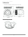
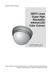
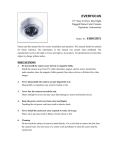
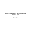
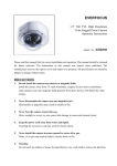
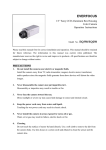
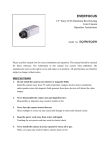
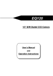
EverFocus
Operation Instructions
1/3” CCD 3-Axis Outdoor IR Dome
Camera
EBD430
Operation Instruction
© 2009 EverFocus Electronics Corp
Please read this manual first for correct installation and operation. This manual should be retained for
future reference. The information in this manual was current when published. The manufacturer
reserves the right to revise and improve its products. All specifications are therefore subject to change
without notice.
All rights reserved. No part of the contents of this manual may be reproduced or transmitted in any form or
by any means without written permission of the EverFocus Electronics Corporation.
Precautions
1. Do not place any object on top of the cover.
2. Be careful when handling the camera, to prevent any damage do not drop it or subject it
to strong shock or vibration. Do not disassemble it or attach it on an unstable base.
3. Install the camera away from TV or radio transmitters, magnets, electric motors,
transformers and audio speakers because the magnetic fields generated from these devices
may distort the video image.
4. Install the camera away from heaters, or other heat generating devices as the high
temperature could cause deformation, discoloration or other damage to the camera.
Install the camera at where the temperature range will stay between -40°C to 50°C (-40°F
to 122°F).
5. Never aim the camera at the sun or other extremely bright objects whether it is in use or
not.
6. Do not touch the surface of CCD sensor directly with your fingers. Use a soft cloth to
remove any dirt from the camera body. If necessary, use lens tissue or a cotton tipped
applicator and ethanol to clean the CCD sensor and the camera lens. When the camera
is not in use, protect the surfaces covering the lens and IR emitters.
7. All warnings on the product and in the operating instructions should be adhered to.
8. Do not use attachments not recommended by the camera manufacturer as they may cause
hazards.
9. Do not allow anything to rest on the power cord. Do not locate this device where the cord
may be abraded or may cause a hazard by persons walking on it.
10. Do not overload wall outlets and extension cords as this can result in fire or electric
shock.
11. Never push objects of any kind into his appliance through cabinet slots as they may touch
dangerous voltage points or short out parts that could result in fire, electric shock or
damage to the camera.
12. Refer all work related to the installation of this product to qualified service personnel or
system installers.
Federal Communication Commission Interference
Statement
This equipment has been tested and found to comply with the limits for a Class A digital
device, pursuant to Part 15 of the FCC Rules. These limits are designed to provide
reasonable protection against harmful interference in a residential installation. This
equipment generates, uses and can radiate radio frequency energy and, if not installed and
used in accordance with the instructions, may cause harmful interference to radio
communications. However, there is no guarantee that interference will not occur in a
particular installation. If this equipment does cause harmful interference to radio or
television reception, which can be determined by turning the equipment off and on, the user is
encouraged to try to correct the interference by one of the following measures:
-
Reorient or relocate the receiving antenna.
-
Increase the separation between the equipment and receiver.
-
Connect the equipment into an outlet on a circuit different from that to which the
receiver is connected.
-
Consult the dealer or an experienced radio/TV technician for help.
FCC Caution: Any changes or modifications not expressly approved by the party responsible
for compliance could void the user's authority to operate this equipment.
This device complies with Part 15 of the FCC Rules. Operation is subject to the following
two conditions: (1) This device may not cause harmful interference, and (2) this device must
accept any interference received, including interference that may cause undesired operation.
Note: There is a screw located in the focus ring and the zoom ring for
waterproofing purposes only. These are NOT set screws!! Please don’t loosen or
remove them.
Table of Contents
1.Product Overview ................................................................ 5
1.1 Features ....................................................................... 5
1.2 Accessory Parts List.................................................... 6
1.3 Specifications .............................................................. 7
1.4 Dimensions................................................................... 8
1.5 Camera Component Description.................................. 9
1.6 Related Products.......................................................... 9
2.Installation ......................................................................... 10
2.1 Wiring and Mounting .................................................. 10
2.2 Adjusting Camera Position ........................................ 13
2.3 Adjusting Zoom and Focus ........................................ 14
4
C CH HA AP PT TE ER R 1 2 P IRNOSDTUA CL TL AOTVI E
OR
NV I E W
Chapter
1
1.Product Overview
Equipped with a SONY Super HAD CCD II and removable IR cut filter, the EBD430 produces a
clear and sharp picture at night or in low light. The long range IR LEDs illuminate up to 30m/98
feet, which allows EBD430 to capture images in complete darkness. Designed with 3-Axis rotation
flexibility, you can easily position the camera at all angles. Moreover, it also provides external
adjustment rings for the vari-focal lens focus and zoom, to easily adjust the field of view. This
camera is waterproof (IP66) and comes with built-in heater for extreme outdoor applications.
Note: There is a screw located in the focus ring and the zoom ring for waterproofing purposes
only. These are NOT set screws!! Please don’t loosen or remove them.
1.1 Features
z
High sensitivity with SONY Super HAD CCD II
z
520 TVL of excellent high resolution technology
z
Up to 30 meters/98 ft. of IR range
z
Vari-focal lens to offer you a wide adjustment of field of view
z
True Day/Night function with removable IR cut filter
z
External control of lens zoom & focus
z
3-Axis rotation for flexible view angle
z
Intelligent Variable-frequency IR control saves electricity and balances brightness
z
Split glass design to avoid undesired IR light reflection into the lens barrel
z
Up to 20,000 hours of high intensity IR LED lifespan
z
Vandal resistant design to prevent damage or tampering
z
Weatherproof and IP66 rated
5
C CH HA AP PT TE ER R 1 2 P IRNOSDTUA CL TL AOTVI E
OR
NV I E W
1.2 Accessory Parts List
Please be careful when you unpack the box to avoid any damage to the electronic device
inside. Check and make sure that you have all the items listed below inside the original box:
Camera Unit x 1
Operation Manual x 1
Installation Template Sticker x 1
Mounting kit includes:
-Long Screw x 4 (for mounting bracket)
-Plastic Anchor x 4
-Hex Key Wrench x 1
-Fixing Screw x 3 (to prevent loosening of base ring)
Note: If an item appears to have been damaged in shipment, replace it properly in its carton and
notify the shipper. If any items are missing, notify your EverFocus Electronics Corp. Sales
Representative or Customer Service. The shipping carton is the safest container in which the unit
may be transported. Save it for possible future use.
6
C CH HA AP PT TE ER R 1 2 P IRNOSDTUA CL TL AOTVI E
OR
NV I E W
1.3 Specifications
Pickup Device
Video Format
Scanning System
Picture Elements
Horizontal Resolution
Sensitivity
S/N Ratio
Electronic Shutter
Lens Type
Back Light Comp.
Auto Gain Control
Auto White Balance
True Day/Night
Gamma Correction
Video Output
Sync. Mode
IR LED Lifespan
Power Source
Power Consumption
Dimensions
Weight
Operating Temperature
IR Distance
IR Wavelength
Vandal Resistant
Weatherproof
Certifications
1/3” SONY Super HAD CCD II
NTSC or PAL
NTSC: 525 TVL, 60 fields/sec.
PAL: 625 TVL, 50 fields/sec.
768 x 494(NTSC) ; 752 x 582 (PAL)
520 TV Lines
0.08 Lux / F=1.2(IR Off), 0 Lux (IR On)
Over 48 dB (AGC Off )
1/50 (1/60) ~ 1/100,000
Vari-focal lens: f=2.9~10mm, f=9~22mm
Yes
Yes
Yes (2500oK ~9000oK)
Yes
0.45
BNC 1.0Vp-p, 75ohm
Internal Sync.
20,000 hours
12VDC/24VAC
12VDC:9W max. (Heater ON & IR LED ON)
24VAC:9.5W max. (Heater ON &IR LED ON)
116.97mm(W) x 144.07mm(H) x 138.9mm(D) ;
4.6”(W) x5.7”(H) x 5.5”(D)
1.15kg/2.54lbs
-40°C to +50°C ; -40℉ to 122℉ (20%~80% Humidity)
30M / 98 ft.
850nm
Yes
IP66
FCC/CE
7
CC HH AA PP TT EE RR 21 IPNRSOTDAUL C
LT
A TOI V
OE
NR V I E W
1.4 Dimensions
116.97mm(W) x 144.07mm(H) x 138.9mm(D) /4.6”(W) x5.7”(H) x 5.5”(D)
Dimension between holes center to center
8
CCHHAAPPTTEERR 21 IPNRSOT DA UL C
LT
A TOI V
OE
NR V I E W
1.5 Camera Component Description
Camera Base
Fixing Ring
Fixing Screws
3-Axis Rotation
Gimbals
Zoom Control
Focus Control
1.6 Related Products
L Type Bracket
Recommended for outdoor installation to protect and tamper-proof the wiring.
9
C H A P T E R
2
I N S T A L L A T I O N
Chapter
2
2.Installation
This chapter will describe, in general terms, how to install the EBD430 camera.
STEPS:
1. Wire and mount the camera, See 2.1
2. Adjust the camera position, See 2.2
3. Adjust focus and zoom, See 2.3
Warning
•
•
To prevent electrical shock, turn off the electrical power before making electrical
connections.
Do not expose the appliance to water or moisture, nor try to operate it in wet areas.
2.1 Wiring and Mounting
2.1.1 Drill the Holes
1. Paste the installation template sticker on the ceiling or wall
2. Drill 5 holes, 4 for screws A,B,C and D,
1 for the power/video cable.
Screw hole A
Screw hole D
Power/Video
Cable Hole
Installation Template
Sticker
Screw hole C
Screw hole B
10
C H A P T E R
2
I N S T A L L A T I O N
Screws
A,B,C,D
Camera base
Outlet hole
Power/Video cable hole
2.1.2 Mounting
1. Remove the camera base from the fixing ring by turning the ring it counter clockwise.
2. Fix the camera base to the ceiling or wall by using the 4 screws provided.
3. Extend the cables to be connected to power and video through the ceiling or wall.
4. Reattach the camera to the base by turning the fixing ring clockwise.
Camera Base
Fixing Ring
11
C H A P T E R
2
I N S T A L L A T I O N
*Warning*
•
•
•
To prevent electrical shock, turn off the electrical power before making electrical
connections.
Do not connect high voltage power to the camera. It may damage the camera.
Do not short circuit the power leads or expose the wires when connecting the power supply
to the camera.
Ceiling Mount:
Camera Base
Wall Mount:
Camera Base
12
C H A P T E R
2
I N S T A L L A T I O N
2.2 Adjusting Camera Position
1. Attach the fixing ring with the dome body to the camera base by turning it clockwise. Please do
tighten it to camera base at this step, so that you can aim the camera.
2. Adjust the direction of the camera to get the direction of view you want.
3. Twist the fixing ring clockwise tightly to lock it to the camera base.
Camera Base
Fixing Ring
Vertically Adjust up and down
Horizontally Adjust 360o
4.
Tighten fixing screws.
Fixing Screws
13
C H A P T E R
2
I N S T A L L A T I O N
2.3 Adjusting Zoom and Focus
There are two rings for adjusting focus and zoom.
1. Adjust the outer ring to the right and left to adjust focus
2. Adjust the inner ring to the right and left to zoom in or zoom out.
Note: There is a screw located in the focus ring and the zoom ring for
waterproofing purposes only. These are NOT set screws!! Please don’t
loosen or remove them.
Adjustment Focus
Adjustment Zoom
14
C H A P T E R
2
I N S T A L L A T I O N
Head Office:
12F, No.79 Sec. 1 Shin-Tai Wu Road,
Hsi-Chih, Taipei, Taiwan
TEL: +886-2-26982334
FAX: +886-2-26982380
www.everfocus.com.tw
Europe Office:
Albert-Einstein-Strasse 1
D-46446 Emmerich, Germany
TEL: +49-2822-9394-0
FAX: +49-2822-939495
www.everfocus.de
USA L.A. Office:
1801 Highland Ave. Unit A
Duarte, CA 91010, U.S.A.
TEL: +1-626-844-8888
FAX: +1-626-844-8838
www.everfocus.com
China Office:
Room 609, Technology Trade
Building,Shangdi Information Industry
Base,Haidian District, Beijing,China
100085
TEL: +86-10-62973336/37/38/39
FAX: +86-10-62971423
www.everfocus.com.cn
USA N.Y. Office:
415 Oser Avenue Unit S
Hauppauge, NY 11788
TEL: +1-631-436-5070
FAX: +1-631-436-5027
www.everfocus.com
Your EverFocus product is designed and
manufactured with high quality materials and
components which can be recycled and
reused.
This symbol means that electrical and
electronic equipment, at their end-of-life,
should be disposed of separately from your
household waste.
Please, dispose of this equipment at your
local community waste collection/recycling
centre.
In the European Union there are separate
collection systems for used electrical and
electronic product.
Please, help us to conserve the environment
we live in!
Japan Office:
1809 WBG MARIBU East 18F,
2-6 Nakase.Mihama-ku.
Chiba city 261-7118, Japan
TEL: +81-43-212-8188
FAX: +81-43-297-0081
www.everfocus.co.jp
Ihr EverFocus Produkt wurde entwickelt und
hergestellt mit qualitativ hochwertigen
Materialien und Komponenten, die recycelt
und wieder verwendet werden können.
Dieses Symbol bedeutet, dass elektrische und
elektronische Geräte am Ende ihrer
Nutzungsdauer vom Hausmüll getrennt
entsorgt werden sollen.
Bitte entsorgen Sie dieses Gerät bei Ihrer
örtlichen kommunalen Sammelstelle oder im
Recycling Centre.
Helfen Sie uns bitte, die Umwelt zu erhalten, in
der wir leben!
P/N: MEBDG01700VerA
15