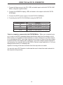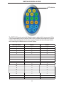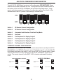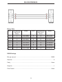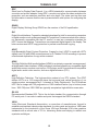
1
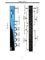
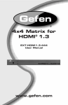
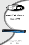
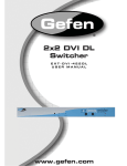
4x4 DVI KVM
Matrix
USER
MANUAL
www.gefen.com
ASKING FOR ASSISTANCE
Technical Support:
Telephone
(818) 772-9100
(800) 545-6900
Fax
(818) 772-9120
Technical Support Hours:
8:00 AM to 5:00 PM Monday through Friday PST
Write To:
Gefen Inc.
c/o Customer Service
20600 Nordhoff Street
Chatsworth, CA 91311
www.gefen.com
[email protected]
Notice
Gefen Inc. reserves the right to make changes in the hardware, packaging and any
accompanying documentation without prior written notice.
The 4x4 DVI DL KVM Matrix is a trademark of Gefen Inc.
© 2009 Gefen Inc., All Rights Reserved
Rev A
TABLE OF CONTENTS
1
Introduction / Operation Notes
2
Features
3
Panel Layout
4
Using the 4x4 DVI DL KVM Matrix
5
RMT16-IR Installation
6
4x4 DVI DL KVM Matrix Configuration
8
RMT-MATRIX-444 Installation
9
RS-232 Interface
10
4x4 DVI Matrix Rack Mount Diagram
11
Specifications
12
Terminology
13
Warranty
INTRODUCTION
Thank you for purchasing the 4x4 DVI DL KVM Matrix.
Now you can easily switch four cross-platform DVI Dual Link computers to four DVI Dual
Link displays. Our 4x4 Dual Link DVI KVM Matrix provides a simple, reliable and highly
effective method of creating multiple computer workstations, with each workstation capable of accessing any one of the computers or sources at any time by remote control.
You also have the option of setting up the four stations locally or extending them with a
Gefen extender. When used with computers, USB 1.1 and Audio matrix control signals
follow the DVI Dual Link input for optimal control.
How It Works
The 4x4 DVI Dual Link KVM Matrix has four Dual Link DVI inputs and four Dual Link DVI
outputs. You simply connect your four computers' DVI Dual Link video ports to the Switcher's
inputs, then connect your four DVI Dual Link displays to the Switcher's outputs. USB 1.1
keyboard and mouse signals and analog audio, once connected, follow the DVI Dual Link
switched input for each computer.
OPERATION NOTES
READ THESE NOTES BEFORE INSTALLING
OR OPERATING THE 4X4 DVI DL KVM MATRIX
• The 4x4 DVI DL KVM Matrix is housed in a metal box for better RF shielding.
• The 4x4 DVI DL KVM Matrix works with all DVI and HDMI displays.
• The 4x4 DVI DL KVM Matrix is not HDCP compliant.
1
FEATURES
Features
•
Increases your productivity by providing you with access to four computers from four
Dual Link workstations
•
Maintains highest resolution digital video with no loss of quality
•
Supports either PC or Mac USB keyboards/mice
•
USB 1.1 Matrix Switching capabilities
•
Supports analog audio matrixing
•
Discrete IR remote (included)
•
Supports single and dual link resolutions up to 3840x2400
•
Supports DDWG standards for DVI monitors
•
Includes rack ears
Includes:
(1) 4x4 DVI DL KVM Matrix
(1) RMT-16IR
(1) 5V Power Supply
(4) 6ft DVI cables
(4) 6ft USB cables
(4) 6ft Audio cables
(1) Set of Rack Ears
2
Display 1
Indicator
3
DVI Outputs
USB/Audio
Outputs
IR Extender Eye Port
Back Panel
Display 4
Indicator
CAT-5 Outputs
Display 3
Indicator
DVI Inputs
USB/Audio
Inputs
Display 2
Indicator
IR Sensor
Front Panel
Connects to 5VDC
Power Supply
RS232 Controller Port
Power Indicator
PANEL LAYOUT
USING THE 4x4 DVI DL KVM MATRIX
1. Connect all the sources to the DVI, USB, and audio inputs on the 4x4 DVI DL KVM
Matrix, using the supplied cables.
2. Connect the HDMI/DVI display, USB, and audio to the outputs on the 4x4 DVI DL
KVM Matrix.
3. Connect the 5VDC power supply to the 4x4 DVI DL KVM Matrix.
4. Controlling the 4x4 DVI DL KVM Matrix using the RMT16-IR:
Pressing Buttons...
1-4
5-8
9-12
13-16
Switches...
Display 1 to view Source 1, 2, 3, or 4
Display 2 to view Source 1, 2, 3, or 4
Display 3 to view Source 1, 2, 3, or 4
Display 4 to view Source 1, 2, 3, or 4
*Note for computers connected to the DVIKVM Matrix - When your computer boots
up, it looks for an EDID (extended display identification data) from the display to tell it
what monitor is connected and what resolution to output. During boot up of the computer you should have ONLY one output selected to one input at a time so that the computer gets the EDID of the display that is selected. If you have multiple outputs selected to
one computer, the computer will read the EDID of the last output selected to it. If all your
displays are the same, or all displays are
capable of running at the same resolution then this step does not matter.
You can also use a DVI Detective to eliminate the need to have that matrix selected to
the computer during bootup.
4
RMT16-IR INSTALLATION
LED Indicator
The RMT-16-IR remote control will allow the user to select which source each of the
4 connected displays will be viewing. Each of the 4 displays are assigned a group of
4 buttons that correspond to the 4 source inputs. Please use the information below
when selecting the desired source for each display.
RMT-16-IR Button
Display
Source
1
1
1
2
1
2
3
1
3
4
1
4
5
2
1
6
2
2
7
2
3
8
2
4
9
3
1
10
3
2
11
3
3
12
3
4
13
4
1
14
4
2
15
4
3
16
4
4
5
4X4 DVI DL KVM MATRIX CONFIGURATION
The 4x4 DVI DL KVM Matrix has a bank of 8 configuration DIP SWITCHES. These
switches are located underneath the unit. Peeling back the black metallic sticker on
the bottom of the 4x4 DVI DL KVM Matrix will reveal the Dip Switch bank. These
service switches are used for a number of configuration options. By default, all Dip
Switches are in the OFF position. Each setting is outlined below.
ON
OFF
1
3
2
5
4
7
6
Switch 1
IR Remote Channel Configuration
Switch 2
IR Remote Channel Configuration
Switch 3
Automatic Link Selection \ Dual Link Only Mode
Switch 4
Not Used
Switch 5
Pre-Empahsis For Display Output 1
Switch 6
Pre-Empahsis For Display Output 2
Switch 7
Pre-Empahsis For Display Output 3
Switch 8
Pre-Empahsis For Display Output 4
8
IR REMOTE CHANNEL CONFIGURATION
Dip Switches 1 and 2 relate to the IR remote control channel that is used by the 4x4 DVI
DL KVM Matrix and RMT-16-IR remote control. Dip Switch 1 and 2 on the 4x4 DVI DL
KVM Matrix must match Dip Switch 1 and 2 on the RMT-16-IR remote control. Please
view the table below to set the channel on 4x4 DVI DL KVM Matrix and IR remote
control. The remote channel for the RMT-16-IR is located underneath it’s battery
cover.
RMT-16-IR REMOTE CONTROL
Remote Channel 1:
Default
4x4 DVI DL KVM Matrix
Remote Channel 1:
Default
Remote Channel 2:
1
1
2
Remote Channel 3:
2
1
2
2
Remote Channel 3:
Remote Channel 4:
1
Remote Channel 2:
1
6
2
1
2
Remote Channel 4:
1
2
1
2
4X4 DVI DL KVM MATRIX CONFIGURATION
AUTOMATIC LINK SELECTION / DUAL LINK ONLY MODE
The 4x4 DVI DL Matrix has the ability to run both Single Link and Dual Link DVI sources.
There is a feature that will either automatically select the link mode, or lock the unit in Dual
Link mode. By default, Dip Switch 3 is in the OFF position (Automatic Link Selection).
Turning Dip Switch 3 to the ON position will lock the unit in Dual Link mode and will only
allow Dual Link signals to pass properly.
PRE-EMPHASIS
Pre-Emphasis is used to help extend a signal travel over a distance of cable. When a DVI
cable connected to a display is over a long cable, it is recommended that Pre-Emphasis
be enabled. Pre-emphasis is enabled by default on all display outputs. For short
cables, disable pre-emphasis on each output by turing it’s corresponding Dip Switch to
the ON position. If any type of extension device, such as a DVI CAT5 Extreme, is used
pre-emphasis must be disabled for proper operation.
7
RMT-MATRIX-444 INSTALLATION (OPTIONAL)
You can use up to 4 RMT-MATRIX-444 units to extend switching functionality to remote
locations. Each unit will allow the user to switch their one display between the 4 inputs
on the DVIKVM-444N. Follow these steps for each RMT-MATRIX-444 that will be used
in your setup.
1. Connect a CAT5/6 cable between the RMT-MATRIX-444 and one of the CAT5 ports
on the rear of the DVIKVM-444N. The ports are labeled as RMT A, B, C, and D and
correspond with DVI out ports 1, 2, 3, and 4.
2. Use the contact buttons on the RMT-MATRIX-444 to switch between the different
inputs connected to the DVIKVM-444N. Optionally, you can use a RMT-4IR (infrared
remote) in conjunction with the RMT-MATRIX-444 to switch inputs from a distance.
Input Selection Buttons
IR Sensor
(For use with optional IR
remote)
Input Selection LED
IR Sensor Extension Port RS-232 Port
(Extension cable not
included)
CAT5/6 Port
8
RS-232 INTERFACE
Binary Table
ASCII Corresponding
RMT16-IR
Button
1
1
2
2
3
3
4
4
5
5
6
6
7
7
8
8
Binary
ASCII
0011 0001
0011 0010
0011 0011
0011 0100
0011 0101
0011 0110
0011 0111
0011 1000
9
a
b
c
d
e
f
g
Corresponding
RMT16-IR
Button
9
10
11
12
13
14
15
16
Binary
0011 1001
0110 0001
0110 0010
0110 0011
0110 0100
0110 0101
0110 0110
0110 0111
RS232 Settings
Bits per second ....................................................................................................... 19200
Data bits .......................................................................................................................... 8
Parity ........................................................................................................................ None
Stop bits ...........................................................................................................................1
Flow Control ............................................................................................................. None
9
4x4 HDTV MATRIX RACK MOUNT DIAGRAM
10
SPECIFICATIONS
Video Amplifier Bandwidth ............................................................................ 165 MHz x 2
Input Video Signal ......................................................................................... 1.2 Volts p-p
Input DDC Signal ................................................................................... 5 Volts p-p (TTL)
Dual Link Maximum Resolution ....................................................... 3840x2400 @ 60 Hz
DVI Connector ..................................................... DVI-I 29 pin female (digital signal only)
USB 1.1 Input Connectors .................................................................................. Type "B"
USB 1.1 Output Connectors ............................................................................... Type "A"
Audio Connectors ........................................................................ 3.5mm mini stereo jack
Power Supply ......................................................................................................... 5V DC
Power Consumption ................................................................................. 40 Watts (max)
Dimensions ................................................................................... 17"W x 1.75"H x 4.5"D
Rack mountable ....................................................................................... 1U Rack Space
Shipping Weight ..................................................................................................... 10 Lbs
11
TERMINOLOGY
DDC
Short form for Display Data Channel. It is a VESA standard for communication between
a monitor and a video adapter. Using DDC, a monitor can inform the video card about its
properties, such as maximum resolution and color depth. The video card can then use
this information to ensure that the user is presented with valid options for configuring the
display.
DDWG
Digital Display Working Group DDWG are the creators of the DVI specification.
DVI
Digital Visual Interface. Connection standard developed by Intel for connecting computers
to digital monitors such as flat panels and DLP projectors. A consumer electronics version,
not necessarily compatible with the PC version, is used as a connection standard for
HDTV tuners and displays. Transmits an uncompressed digital signal to the display. The
latter version uses HDCP copy protection to prevent unauthorized copying.
HDCP
High-Bandwidth Digital Content Protection. Created by Intel, HDCP is used with HDTV
signals over DVI and HDMI connections and on D-Theater D-VHS recordings to prevent
unauthorized duplication of copy written material.
HDMI
The High-Definition Multi-media Interface (HDMI) is an industry-supported, uncompressed,
all-digital audio/video interface. HDMI provides an interface between any compatible digital
audio/video source, such as a set-top box, DVD player, and A/V receiver and a compatible
digital audio and/or video monitor, such as a digital television (DTV).
HDTV
High-Definition Television. The high-resolution subset of our DTV system. The ATSC
defines HDTV as a 16:9 image with twice the horizontal and vertical resolution of our
existing system, accompanied by 5.1 channels of Dolby Digital audio. The CEA defines
HDTV as an image with 720 progressive or 1080 interlaced active (top to bottom) scan
lines. 1280:720p and 1920:1080i are typically accepted as high-definition scan rates.
RS-232
Recommended Standard 232. This is the de facto standard for communication through
PC serial ports. It can refer to cables and ports that support the RS232 standard.
VESA
Video Electronic Standards Association, a consortium of manufacturers formed to
establish and maintain industry wide standards for video cards and monitors. VESA was
instrumental in the introduction of the Super VGA and Extended VGA video graphics
standards with a refresh rate of 70 Hz, minimizing flicker and helping to reduce user
eyestrain and fatigue.
12
WARRANTY
Gefen warrants the equipment it manufactures to be free from defects in material
and workmanship.
If equipment fails because of such defects and Gefen is notified within two (2)
years from the date of shipment, Gefen will, at its option, repair or replace the
equipment, provided that the equipment has not been subjected to mechanical,
electrical, or other abuse or modifications. Equipment that fails under conditions
other than those covered will be repaired at the current price of parts and labor in
effect at the time of repair. Such repairs are warranted for ninety (90) days from
the day of reshipment to the Buyer.
This warranty is in lieu of all other warranties expressed or implied, including
without limitation, any implied warranty or merchantability or fitness for any
particular purpose, all of which are expressly disclaimed.
1.
Proof of sale may be required in order to claim warranty.
2.
Customers outside the US are responsible for shipping charges to and from
Gefen.
3.
Copper cables are limited to a 30 day warranty and cables must be in their
original condition.
The information in this manual has been carefully checked and is believed to
be accurate. However, Gefen assumes no responsibility for any inaccuracies
that may be contained in this manual. In no event will Gefen be liable for
direct, indirect, special, incidental, or consequential damages resulting from
any defect or omission in this manual, even if advised of the possibility of such
damages. The technical information contained herein regarding the features and
specifications is subject to change without notice.
For the latest warranty coverage information, please visit Gefen’s Warranty web
page at http://www.gefen.com/kvm/aboutus/warranty.jsp
PRODUCT REGISTRATION
Please register your product online by visiting Gefen’s web site at
http://www.gefen.com/kvm/Registry/Registration.jsp
13
*ma-DVIKVM-444DL*
Rev A
20600 Nordhoff St., Chatsworth CA 91311
1-800-545-6900
818-772-9100
www.gefen.com
Pb
fax: 818-772-9120
[email protected]