1
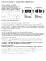
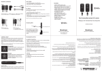
WR200
WR200 WIRELESS EXTENDER
Owners manual
www.audiopro.com
www.audiopro.se
© Audio Pro AB Sverige
Audio Pro® , Audio Pro logotypen, ‘a’ symbolen, och ace-bass® är registrerade varumärken av Audio Pro AB, Sverige.
Alla rättigheter reserverade. Audio Pro följer en policy om ständig produktutveckling.
Specifikationer kan ändras utan föregående meddelande.
© Audio Pro AB Sweden
Audio Pro®, the Audio Pro logotype, the ‘a’ symbol, and ace-bass® are all registered trademarks of Audio Pro AB, Sweden.
All rights reserved. Audio Pro follows a policy of continuous advancement in development.
Specifications may be changed without notice.
ENGLISH
Features
specifications
- Extended room to room: up to 20m
- Extended range same room: up to 50m
- Extended range in line of sight: up to 100m
- Wireless range between unit 1 & 2: 10-30m
- Wireless full CD quality sound
- Sample rate: 48 KHz
- Dedicated proprietary protocol
- Master/zone volume relay
Transmitting/receiving:
Unit 1:
2.4GHz receiver + 5.8GHz transmitter
Unit 2:
5.8GHz receiver + 2.4GHz transmitter
Type:
Wireless extender for Audio Pro network
Size WxHxD: 95x110x30mm
OVERVIEW & Contents
WR200 unit 1
House Code LED
Indicates wireless status for 2.4GHz. Solid blue
for connection, flashing blue for lost connection.
Red for no wireless connection or no transmission.
Side: House Code switch
Side: Extender channel switch
WR200 unit 2
EX channel LED
Indicates wireless status for 5.8GHz. Solid blue
for connection, flashing blue for lost connection.
Red for no wireless connection or no transmission.
Bottom: Power input and line output
Connect to enclosed
power adaptor
2 x powersupply
Connect optional device with
line input (stereo/receiver/
powered speakers).
Functionality and performance
How WR200 works
The WR200 system consists of two units,
1 and 2. Unit 1 is the first unit and
receives a signal (2.4GHz) from the TX100
transmitter and then relays the signal on
a different band (5.8GHz) to unit 2. Unit
2 then transmits the signal on the 2.4GHz
band to all speakers.
Because the 5.8GHz band is stronger but
shorter in range than the 2.4GHz band,
WR200 will work around any difficult
conditions in a house that the wifi signal
encounters. We also use the 5.8Ghz band
to avoid 2.4GHz audio signal conflict.
2.4
GHz
5.8
GHz
UNIT 1
Receives 2.4GHz
Transmits 5.8GHz
5.8
GHz
2.4
GHz
UNIT 2
Receives 5.8GHz
Transmits 2.4GHz
AVOIDING SIGNAL CONFLICTS BY USING HOUSE CODES
On each unit there are House Code and Extender channel switches. When using WR200, it
is important that unit 2 is set to a different House Code than that used by the TX100 transmitter. This is because, if set to the same House Code, unit 1 will receive signals from both TX100
and unit 2 and will not know which signal to use. This would result in a conflict in signals and
the WR200 would not function correctly.
Extender channel
The WR200 has 3 different settings for the internal 5.8GHz channels.
This feature makes it possible to use up to three WR200 systems in series in order to extend
network even further. Or if your home has several wifi problems that need to be handled and
circumvented. Each pair of WR200s must be set to the same extender channel X,Y or Z.
master and zone volume
All speakers in the Living series can handle master volumes and zone volumes. All volume
commands are relayed via WR200. For example, if you have speakers connected before
and after the WR200 in zone A, and if you adjust the volume on any speaker in zone A, all
the speakers in zone A will be adjusted. The same principle applies for the master volume
functionality, which adjusts all speakers on same House Code.
When placing wr200
When you position units 1 and 2, you can use the LED indicators as a guide. They show a
continuous blue light to indicate that a connection has been established between transmitter
and receiver. When correctly placed, all LED’s on both units 1 and 2 will show a continuous
blue light. Try different placements to achieve the best signal. The TX100 transmitter must be
connected to a sound source and have a continuous blue light showing.
The WR200 can be hung on a wall using the hole in the rear.
BASIC CONNECTION
All speakers located within range are set
to the same House Code as the TX100.
TX100 transmitter
Range: 20-100m
UNIT 1
EXTENDER CHANNEL:
Set to X, Y or Z
UNIT 1
HOUSE CODE: Same as on the
TX100 transmitter ( 1, 2 or 3)
Range: 15-30m
UNIT 2
EXTENDER CHANNEL:
Set to same channel X, Y
or Z as on UNIT 1.
UNIT 2
HOUSE CODE:
Set to different House Code
than TX100.
Example: Set TX100 and UNIT
1 to House Code 1, set UNIT 2
to House Code 2 or 3.
Range: 20-100m
Set all LV-speakers to same House Code
as UNIT 2 in order to receive a signal.
example connections
1. Extending network
2. bypass difficult wall conditions
3. bypass difficult floor conditions
4. Extending network
in different directions
Unit 1 sending to two or more unit 2 modules.
(Unit 2 (WER202) modules of WR200 are
also sold separately.
5. Extending network with up to three wr200 sets
A
B
C
If using more than one WR200 set, use different extender channels (X, Z and Y) for all sets.
Change the house code accordingly;
Set A: receive house code 1, send house code 2.
Set B: receive house code 2, send house code 3.
Set C: receive house code 3, send house code 1.
Connect device directly by cable to WR200
Stereo/Receiver
Powered speakers
There is a line output on both unit 1 and 2. With this feature you can connect a stereo/
receiver or powered speakers directly to the WR200 via a cable. The devices will then play
wireless audio at the same time as your wireless Living speakers.
Note: You can connect any device with line input.
The lightning flash with arrowhead symbol, within an
equilateral triangle, is intended to alert the user to the
presence of uninsulated “dangerous voltage” within the
product’s enclosure that may be of sufficient magnitude
to constitute a risk of electric shock to persons.
The exclamation point within an equilateral triangle is
intended to alert the user to the presence of important
operating and maintenance (servicing) instructions in
the literature accompanying the appliance.
Important Safety Instructions
1.
2.
3.
4.
5.
6.
Read these instructions.
Keep these instructions.
Heed all warnings.
Follow all instructions.
Do not use this apparatus near water.
Clean only with dry cloth.
7. Do not block any ventilation openings. Install in accordance with the manufacturer’s instructions.
8. Do not install near any heat sources such as radiators,
heat registers, stoves, or other apparatus (including amplifiers) that produce heat.
9. Protect the power cord from being walked on or
pinched particularly at plugs, convenience receptacles,
and the point where they exit from the apparatus.
10. Only use attachments/accessories specified by the
manufacturer.
11. Unplug this apparatus during lightning storms or when
unused for long periods of time.
12. Refer all servicing to qualified service personnel.
Servicing is required when the apparatus has been damaged in any way, such as power-supply cord or plug is
damaged, liquid has been spilled or objects have fallen
into the apparatus, the apparatus has been exposed to
rain or moisture, does not operate normally, or has been
dropped.
13. Damage Requiring Service
Unplug the apparatus from the wall outlet and refer servicing to qualified service personnel under thee following
conditions:
A. When the power-supply cord or plug is damaged,
B. If liquid has been spilled, or objects have fallen into the
apparatus,
C. If the apparatus has been exposed to rain or water,
WARNING:
TO REDUCE THE RISK OF FIRE OR ELECTRIC
SHOCK, DO NOT EXPOSE THIS APPARATUS
TO RAIN OR MOISTURE.
CAUTION:
TO REDUCE THE RISK OF ELECTRIC SHOCK,
DO NOT REMOVE COVER (OR BACK).
NO USER-SERVICEABLE PARTS INSIDE.
REFER SERVICING TO QUALIFIED
SERVICE PERSONNEL.
D. If the apparatus does not operate normally by following
the operating instructions. Adjust only those controls that
are covered by the operating instructions as an improper
adjustment of other controls may result in damage and will
often require extensive work by a qualified technician to
restore the apparatus to its normal operation,
E. If the apparatus has been dropped or damaged in any
way, and
F. When the apparatus exhibits a distinct change in performance this indicates a need for service.
14. Object and Liquid Entry
Never push objects of any kind into the apparatus through
openings as they may touch dangerous voltage points or
short-out parts that could result in a fire or electric shock.
The apparatus shall not be exposed to dripping or splashing and no objects filled with liquids, such as vases shall
be placed on the apparatus. Don’t put candles or other
burning objects on top of this unit.
15. Batteries
Always consider the environmental issues and follow local
regulations when disposing of batteries.
16. If you install the apparatus in a built-in installation,
such as a bookcase or rack, ensure that there is adequate
ventilation. Leave 20 cm (8”) of free space at the top and
sides and 10 cm (4”) at the rear. The rear edge of the
shelf or board above the apparatus shall be set 10 cm (4”)
away from the rear panel or wall, creating a flue-like gap
for warm air to escape.
17. The power supply and power cord for this apparatus is
intended for indoor use only.
18. Only use the enclosed AC adaptor.