1
SUPER
®
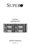
SC836 Chassis
Series
SC836A-R1200B
SC836BA-R920B
SC836BA-R1K28B
SC836TQ-R500B
SC836TQ-R800V/B
SC836TQ-R710B
SC836E16-R500B
SC836E16/E26-R1200B
SC836BE16/E26-R920B
SC836BE16/E26-R1K28B
SC836BHA-R1K28B
SC836BHE16/E26-R1K28B
User’s Manual
2.1a
SC836 Chassis Manual
The information in this User’s Manual has been carefully reviewed and is believed to be accurate.
The vendor assumes no responsibility for any inaccuracies that may be contained in this document,
makes no commitment to update or to keep current the information in this manual, or to notify any
person or organization of the updates. Please Note: For the most up-to-date version of this
manual, please see our web site at www.supermicro.com.
Super Micro Computer, Inc. ("Supermicro") reserves the right to make changes to the product
described in this manual at any time and without notice. This product, including software and
documentation, is the property of Supermicro and/or its licensors, and is supplied only under a
license. Any use or reproduction of this product is not allowed, except as expressly permitted by
the terms of said license.
IN NO EVENT WILL SUPERMICRO BE LIABLE FOR DIRECT, INDIRECT, SPECIAL, INCIDENTAL,
SPECULATIVE OR CONSEQUENTIAL DAMAGES ARISING FROM THE USE OR INABILITY TO
USE THIS PRODUCT OR DOCUMENTATION, EVEN IF ADVISED OF THE POSSIBILITY OF
SUCH DAMAGES. IN PARTICULAR, SUPERMICRO SHALL NOT HAVE LIABILITY FOR ANY
HARDWARE, SOFTWARE, OR DATA STORED OR USED WITH THE PRODUCT, INCLUDING THE
COSTS OF REPAIRING, REPLACING, INTEGRATING, INSTALLING OR RECOVERING SUCH
HARDWARE, SOFTWARE, OR DATA.
Any disputes arising between manufacturer and customer shall be governed by the laws of Santa
Clara County in the State of California, USA. The State of California, County of Santa Clara shall
be the exclusive venue for the resolution of any such disputes. Super Micro's total liability for all
claims will not exceed the price paid for the hardware product.
California Best Management Practices Regulations for Perchlorate Materials: This Perchlorate
warning applies only to products containing CR (Manganese Dioxide) Lithium coin cells. “Perchlorate
Material-special handling may apply. See www.dtsc.ca.gov/hazardouswaste/perchlorate”
WARNING: Handling of lead solder materials used in this
product may expose you to lead, a chemical known to
the State of California to cause birth defects and other
reproductive harm.
Manual Revision 2.1a
Release Date: May 14, 2014
Unless you request and receive written permission from Super Micro Computer, Inc., you may not
copy any part of this document.
Information in this document is subject to change without notice. Other products and companies
referred to herein are trademarks or registered trademarks of their respective companies or mark
holders.
Copyright © 2014 by Super Micro Computer, Inc.
All rights reserved.
Printed in the United States of America
ii
Preface
Preface
About This Manual
This manual is written for professional system integrators and PC technicians. It
provides information for the installation and use of the SC836 3U chassis. Installation and maintenance should be performed by experienced technicians only.
Supermicro’s SC836 3U chassis features a unique and highly-optimized design.
The chassis is equipped with a redundant 500W, 710W (DC), 800W, 920W, 1200W
or 1280W high-efficiency power supply. High-performance fans provide ample optimized cooling for the chassis and sixteen hot-swappable drives offer maximum
storage capacity in a 3U form factor.
This document lists compatible parts available when this document was published.
Always refer to the our web site for updates on supported parts and configurations.
iii
SC836 Chassis Manual
Manual Organization
Chapter 1 Introduction
The first chapter provides a list of the main components included with the SC836
chassis and describes the main features of the chassis. This chapter also includes
contact information.
Chapter 2 Standardized Warning Statements for AC/DC Systems
This chapter lists warnings, precautions, and system safety. You should thoroughly
familiarize yourself with this chapter for a general overview of safety precautions
that should be followed before installing and servicing this chassis.
Chapter 3 Chassis Components
Refer here for details on this chassis model including the fans, bays, airflow shields,
and other components.
Chapter 4 System Interface
This chapter provides details on the system interface, which includes the functions
and information provided by the control panel on the chassis as well as other LEDs
located throughout the system.
Chapter 5 Chassis Setup and Maintenance
Refer to this chapter for detailed information on this chassis. You should follow the
procedures given in this chapter when installing, removing, or reconfiguring your
chassis.
Chapter 6 Advanced Setup
This chapter includes detailed instructions for advanced setup configurations including multiple chassis connections.
Chapter 7 Rack Installation
Refer to this chapter for detailed information on chassis rack installation. You should
follow the procedures given in this chapter when installing, removing or reconfiguring
your chassis into a rack environment.
iv
Preface
Compatible Backplanes
This section lists compatible cables, power supply specifications, and compatible
backplanes. Not all compatible backplanes are listed. Refer to our web site for the
latest compatible backplane information.
Appendix A SC836 Chassis Cables
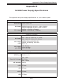
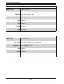
Appendix B SC836 Power Supply Specifications
Appendix C BPN-SAS2-836EL Series Backplane Specifications
Appendix D BPN-SAS-836TQ Backplane Specifications
Appendix E BPN-SAS-836A Backplane Specifications
Appendix F PCC-JBWR2 and CSE-PTJBOD-CB2 Power Control
Card Specifications
Appendix G SC836B Chassis Specifications
v
SC836 Chassis Manual
Table of Contents
Chapter 1 Introduction
1-1Overview.......................................................................................................... 1-1
1-2
Shipping List..................................................................................................... 1-2
Part Numbers................................................................................................... 1-2
1-3
Chassis Features............................................................................................. 1-3
CPU Support.................................................................................................... 1-3
I/O Expansion slots.......................................................................................... 1-3
Peripheral Drives.............................................................................................. 1-3
Other Features................................................................................................. 1-3
SCSI Drives...................................................................................................... 1-3
1-4
Contacting Supermicro..................................................................................... 1-4
1-5
Returning Merchandise for Service................................................................. 1-5
Chapter 2 Standardized Warning Statements for AC/DC Systems
2-1
About Standardized Warning Statements........................................................ 2-1
Warning Definition............................................................................................ 2-1
Installation Instructions..................................................................................... 2-4
Circuit Breaker................................................................................................. 2-5
Power Disconnection Warning......................................................................... 2-6
Equipment Installation...................................................................................... 2-8
Restricted Area................................................................................................. 2-9
Battery Handling............................................................................................. 2-10
Redundant Power Supplies........................................................................... 2-12
Backplane Voltage......................................................................................... 2-13
Comply with Local and National Electrical Codes......................................... 2-14
Product Disposal............................................................................................ 2-15
Hot Swap Fan Warning.................................................................................. 2-16
DC Power Supply ......................................................................................... 2-18
DC Power Disconnection............................................................................... 2-20
Hazardous Voltage or Energy Present on DC Power Terminals................... 2-21
Chapter 3 Chassis Components
3-1Overview.......................................................................................................... 3-1
3-2Components..................................................................................................... 3-1
Chassis and Chassis Bays.............................................................................. 3-1
vi
Preface
Backplane......................................................................................................... 3-1
Fans................................................................................................................. 3-1
Mounting Rails................................................................................................. 3-2
Power Supply................................................................................................... 3-2
Air Shroud........................................................................................................ 3-2
3-3
Where to get Replacement Components......................................................... 3-2
Chapter 4 System Interface
4-1Overview.......................................................................................................... 4-1
4-2
Control Panel Buttons...................................................................................... 4-2
4-3
Control Panel LEDs......................................................................................... 4-2
4-4
Drive Carrier LEDs........................................................................................... 4-4
Chapter 5 Basic Chassis Setup and Maintenance
5-1Overview.......................................................................................................... 5-1
5-2Installation........................................................................................................ 5-1
5-3
Removing the Chassis Cover.......................................................................... 5-2
5-4
Installing the Hard Drives................................................................................. 5-3
Removing Hard Drive Carriers from the Chassis............................................ 5-3
Installing a Hard Drive to the Hard Drive Carrier............................................ 5-3
5-5
Installing the Motherboard............................................................................... 5-5
Permanent and Optional Standoffs.................................................................. 5-5
Standoffs Labeling........................................................................................... 5-5
Motherboard Installation................................................................................... 5-5
Power Supply Connections.............................................................................. 5-6
I/O Shield and Expansion Card Setup............................................................. 5-7
Installing an I/O Panel...................................................................................... 5-7
Installing an Expansion Card........................................................................... 5-8
5-6
Installing the Air Shroud, Rear Fan, and Checking Airflow............................. 5-9
Installing the Air Shroud................................................................................... 5-9
Installing Rear System Fans.......................................................................... 5-10
Checking the Server's Airflow.........................................................................5-11
5-7
Chassis Maintenance..................................................................................... 5-12
Replacing System Fans................................................................................. 5-12
Replacing the Power Supply.......................................................................... 5-13
Replacing the Power Distributor.................................................................... 5-14
Replacing the Front Panel............................................................................. 5-15
Replacing or Installing the Front Port Panel.................................................. 5-15
vii
SC836 Chassis Manual
Chapter 6 Advanced Setup
6-1Overview.......................................................................................................... 6-1
6-2
Dual Ports and Expanders............................................................................... 6-2
Single Ports...................................................................................................... 6-2
Dual Ports........................................................................................................ 6-2
6-3Failover............................................................................................................. 6-3
Single Host Bus Adapter.................................................................................. 6-3
Single Host Bus Adapter Failover.................................................................... 6-3
Dual Host Bus Adapter ................................................................................... 6-4
Dual Host Bus Adapter Failover...................................................................... 6-4
6-4
Cascading Backplanes..................................................................................... 6-4
Power Control Card......................................................................................... 6-4
Chapter 7 Rack Installation
7-1Overview.......................................................................................................... 7-1
7-2
Unpacking the System..................................................................................... 7-1
7-3
Preparing for Setup.......................................................................................... 7-1
Choosing a Setup Location.............................................................................. 7-1
7-4
Warnings and Precautions............................................................................... 7-2
Rack Precautions............................................................................................. 7-2
General Server Precautions............................................................................. 7-2
7-5
Rack Mounting Considerations........................................................................ 7-3
Ambient Operating Temperature...................................................................... 7-3
Reduced Airflow............................................................................................... 7-3
Mechanical Loading......................................................................................... 7-3
Circuit Overloading........................................................................................... 7-3
Reliable Ground............................................................................................... 7-3
7-6
Rack Mounting Instructions.............................................................................. 7-4
Identifying the Sections of the Rack Rails....................................................... 7-4
Locking Tabs.................................................................................................... 7-5
Releasing the Inner Rail.................................................................................. 7-5
Installing The Inner Rails on the Chassis........................................................ 7-6
Installing the Outer Rails on the Rack............................................................. 7-7
Standard Chassis Installation.......................................................................... 7-8
Optional Quick Installation Method.................................................................. 7-9
viii
Preface
Appendix A SC836 Chassis Cables
Appendix B SC836 Power Supply Specifications
Appendix C BPN-SAS-836EL Backplane Specifications
Appendix D BPN-SAS-836TQ Backplane Specifications
Appendix E SAS-836A Backplane Specifications
Appendix F PCC-JBPWR2 and CSE-PTJBOD-CB1
Appendix G SC836B Chassis Specifications
ix
SC836 Chassis Manual
Notes
x
Chapter 1: Introduction
Chapter 1
Introduction
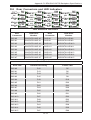
1-1Overview
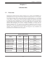
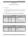
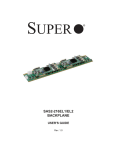
Supermicro's SC836 storage chassis supports up to sixteen hot-swappable 3.5"
SAS/SATA hard drive bays, the industry's highest storage density for a 3U system.
The SC836 includse 100% cooling redundancy and high efficiency (1+1) redundant
710W, 800W, or 1200W (93%) Gold Level power supplies with PM BUS functionality
for enhanced power management. The SC836 is optimized for the next-generation
dual-processor Intel® Xeon® (5500 series) and AMD Opteron™ platforms. Direct
attached HDD backplane (TQ version), multilane backplane (A version) and expanders' backplane (E1, E2 versions) are available for application specific solution
optimization. Heavy duty palletized packaging is available to ensure secure system
reliability during shipping and tool-less, roller rail designs for easy installation and
maintenance are standard with each system.
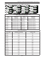
SC836 Chassis Series
HDD
I/O Slots
Power
Supply
SC836BHA-R1K28B
16x SAS
7x FF
1280W
(Redundant, Platinum)
SC836BHE16-R1K28B
SC836BHE26-R1K28B
16x SAS
7x FF
1280W
(Redundant, Platinum)
SC836BE16-R1K28B
SC836BE26-R1K28B
16x SAS
7x FF
1280W
(Redundant, Platinum)
SC836BA-R1K28B
16x SAS
7x FF
1280W
(Redundant, Platinum)
SC836E16-R1200B
SC836E26-R1200B
16x SAS/SATA
7x FF
1280W
(Redundant, Platinum)
SC836A-R1200B
16x SAS/SATA
7x FF
1280W
(Redundant, Platinum)
Model
1-1
SC836 Chassis Manual
SC836 Chassis Series
SC836BE16-R920B
SC836BE26-R920B
16x SAS
7x FF
920W
(Redundant, Platinum)
SC836BA-R920B
16x SAS
7x FF
920W
(Redundant, Platinum)
SC836TQ-R800V
SC836TQ-R800B
16x SAS/SATA
7x FF
800W
(Redundant)
SC836TQ-R710B
16x SAS/SATA
7x FF
710W DC
(Redundant)
SC836TQ-R500B
16x SAS/SATA
7x FF
500W
(Redundant, Platinum)
SC836E16-R500B
16x SAS/SATA
7x FF
500W
(Redundant, Platinum)
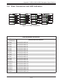
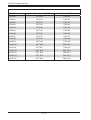
1-2 Shipping List
Part Numbers
Please visit the Supermicro web site for the latest shipping lists and part numbers
for your particular chassis model at www.supermicro.com.
1-2
Chapter 1: Introduction
1-3 Chassis Features
The SC836 3U high-performance chassis includes the following features:
CPU Support
The SC836 chassis supports a DP Dual-core Xeon processor. Please refer to the
motherboard specifications pages on our web site for updates on supported processors for this chassis
Hard Drives
The SC836 chassis features sixteen slots for SAS or SAS/SATA drives. These
drives are hot-swappable, meaning that once set up correctly these drives may be
removed without powering down the server. In addition, these drives support SES2.
I/O Expansion slots
Each version of the SC836 chassis includes seven full I/O expansion slots.
Peripheral Drives
Each SC836 chassis supports one slim DVD-ROM drive (optional) These drives
allow you to quickly install software or save data.
Other Features
Other onboard features are included to promote system health. These include various five cooling fans, a convenient power switch, reset button, and LED indicators
SCSI Drives
For information on SCSI drives contact the Supermicro Technical Support Department at www.supermicro.com
1-3
SC836 Chassis Manual
1-4 Contacting Supermicro
Headquarters
Address:
Super Micro Computer, Inc.
980 Rock Ave.
San Jose, CA 95131 U.S.A.
Tel:
+1 (408) 503-8000
Fax:
+1 (408) 503-8008
Email:
[email protected] (General Information)
[email protected] (Technical Support)
Web Site:
www.supermicro.com
Europe
Address:
Super Micro Computer B.V.
Het Sterrenbeeld 28, 5215 ML
's-Hertogenbosch, The Netherlands
Tel:
+31 (0) 73-6400390
Fax:
+31 (0) 73-6416525
Email:
[email protected] (General Information)
[email protected] (Technical Support)
[email protected] (Customer Support)
Web Site:
www.supermicro.nl
Asia-Pacific
Address:
Super Micro Computer, Inc.
3F, No. 150, Jian 1st Rd.
Zhonghe Dist., New Taipei City 235
Taiwan (R.O.C)
Tel:
+886-(2) 8226-3990
Fax:
+886-(2) 8226-3992
Email:
[email protected]
Web Site:
www.supermicro.com.tw
1-4
Chapter 1: Introduction
1-5 Returning Merchandise for Service
A receipt or copy of your invoice marked with the date of purchase is required before any warranty service will be rendered. You can obtain service by calling your
vendor for a Returned Merchandise Authorization (RMA) number. When returning to
the manufacturer, the RMA number should be prominently displayed on the outside
of the shipping carton, and mailed prepaid or hand-carried. Shipping and handling
charges will be applied for all orders that must be mailed when service is complete.
For faster service, RMA authorizations may be requested online (http://www.
supermicro.com/support/rma/).
Whenever possible, repack the chassis in the original Supermicro carton, using the
original packaging material. If these are no longer available, be sure to pack the
chassis securely, using packaging material to surround the chassis so that it does
not shift within the carton and become damaged during shipping.
This warranty only covers normal consumer use and does not cover damages incurred in shipping or from failure due to the alteration, misuse, abuse or improper
maintenance of products.
During the warranty period, contact your distributor first for any product problems.
1-5
SC836 Chassis Manual
Notes
1-6
Chapter 2: Warning Statements for AC/DC Systems
Chapter 2
Standardized Warning Statements for AC/DC Systems
2-1 About Standardized Warning Statements
The following statements are industry standard warnings, provided to warn the user
of situations which have the potential for bodily injury. Should you have questions
or experience difficulty, contact Supermicro's Technical Support department
for assistance. Only certified technicians should attempt to install or configure
components.
Read this appendix in its entirety before installing or configuring components in the
Supermicro chassis.
These warnings may also be found on our web site at http://www.supermicro.com/
about/policies/safety_information.cfm.
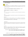
Warning Definition
Warning!
This warning symbol means danger. You are in a situation that could cause bodily
injury. Before you work on any equipment, be aware of the hazards involved with
electrical circuitry and be familiar with standard practices for preventing accidents.
警告の定義
この警告サインは危険を意味します。
人身事故につながる可能性がありますので、いずれの機器でも動作させる前に、
電気回路に含まれる危険性に注意して、標準的な事故防止策に精通して下さい。
此警告符号代表危险。
您正处于可能受到严重伤害的工作环境中。在您使用设备开始工作之前,必须充分
意识到触电的危险,并熟练掌握防止事故发生的标准工作程序。请根据每项警告结
尾的声明号码找到此设备的安全性警告说明的翻译文本。
此警告符號代表危險。
您正處於可能身體可能會受損傷的工作環境中。在您使用任何設備之前,請注意觸
電的危險,並且要熟悉預防事故發生的標準工作程序。請依照每一注意事項後的號
碼找到相關的翻譯說明內容。
2-1
SC119X Chassis Manual
Warnung
WICHTIGE SICHERHEITSHINWEISE
Dieses Warnsymbol bedeutet Gefahr. Sie befinden sich in einer Situation, die zu
Verletzungen führen kann. Machen Sie sich vor der Arbeit mit Geräten mit den
Gefahren elektrischer Schaltungen und den üblichen Verfahren zur Vorbeugung
vor Unfällen vertraut. Suchen Sie mit der am Ende jeder Warnung angegebenen
Anweisungsnummer nach der jeweiligen Übersetzung in den übersetzten
Sicherheitshinweisen, die zusammen mit diesem Gerät ausgeliefert wurden.
BEWAHREN SIE DIESE HINWEISE GUT AUF.
INSTRUCCIONES IMPORTANTES DE SEGURIDAD
Este símbolo de aviso indica peligro. Existe riesgo para su integridad física. Antes
de manipular cualquier equipo, considere los riesgos de la corriente eléctrica y
familiarícese con los procedimientos estándar de prevención de accidentes. Al
final de cada advertencia encontrará el número que le ayudará a encontrar el texto
traducido en el apartado de traducciones que acompaña a este dispositivo.
GUARDE ESTAS INSTRUCCIONES.
IMPORTANTES INFORMATIONS DE SÉCURITÉ
Ce symbole d'avertissement indique un danger. Vous vous trouvez dans une
situation pouvant entraîner des blessures ou des dommages corporels. Avant
de travailler sur un équipement, soyez conscient des dangers liés aux circuits
électriques et familiarisez-vous avec les procédures couramment utilisées pour
éviter les accidents. Pour prendre connaissance des traductions des avertissements
figurant dans les consignes de sécurité traduites qui accompagnent cet appareil,
référez-vous au numéro de l'instruction situé à la fin de chaque avertissement.
CONSERVEZ CES INFORMATIONS.
תקנון הצהרות אזהרה
על מנת להזהיר את המשתמש מפני חבלה,הצהרות הבאות הן אזהרות על פי תקני התעשייה
יש ליצור קשר עם מחלקת תמיכה, במידה ויש שאלות או היתקלות בבעיה כלשהי.פיזית אפשרית
. טכנאים מוסמכים בלבד רשאים להתקין או להגדיר את הרכיבים.טכנית של סופרמיקרו
.יש לקרוא את הנספח במלואו לפני התקנת או הגדרת הרכיבים במארזי סופרמיקרו
2-2
Chapter 2: Warning Statements for AC/DC Systems
. تحذٌز!هذا الزهز ٌعًٌ خطز اًك فً حالة ٌوكي أى تتسبب فً اصابة جسذٌة
كي على علن بالوخاطز الٌاجوة عي الذوائز،قبل أى تعول على أي هعذات
الكهزبائٍة
وكي على دراٌة بالووارسات الىقائٍة لوٌع وقىع أي حىادث
استخذم رقن البٍاى الوٌصىص فً ًهاٌة كل تحذٌز للعثىر تزجوتها
안전을 위한 주의사항
경고!
이 경고 기호는 위험이 있음을 알려 줍니다. 작업자의 신체에 부상을 야기 할 수
있는 상태에 있게 됩니다. 모든 장비에 대한 작업을 수행하기 전에 전기회로와
관련된 위험요소들을 확인하시고 사전에 사고를 방지할 수 있도록 표준
작업절차를 준수해 주시기 바랍니다.
해당 번역문을 찾기 위해 각 경고의 마지막 부분에 제공된 경고문 번호를
참조하십시오
BELANGRIJKE VEILIGHEIDSINSTRUCTIES
Dit waarschuwings symbool betekent gevaar. U verkeert in een situatie die
lichamelijk letsel kan veroorzaken. Voordat u aan enige apparatuur gaat werken,
dient u zich bewust te zijn van de bij een elektrische installatie betrokken risico's
en dient u op de hoogte te zijn van de standaard procedures om ongelukken te
voorkomen. Gebruik de nummers aan het eind van elke waarschuwing om deze te
herleiden naar de desbetreffende locatie.
BEWAAR DEZE INSTRUCTIES
2-3
SC119X Chassis Manual
Installation Instructions
Warning!
Read the installation instructions before connecting the system to the power source.
設置手順書
システムを電源に接続する前に、設置手順書をお読み下さい。
警告
将此系统连接电源前,请先阅读安装说明。
警告
將系統與電源連接前,請先閱讀安裝說明。
Warnung
Vor dem Anschließen des Systems an die Stromquelle die Installationsanweisungen
lesen.
¡Advertencia!
Lea las instrucciones de instalación antes de conectar el sistema a la red de
alimentación.
Attention
Avant de brancher le système sur la source d'alimentation, consulter les directives
d'installation.
.יש לקרוא את הוראות התקנה לפני חיבור המערכת למקור מתח
اقر إرشادات التركيب قبل توصيل النظام إلى مصدر للطاقة
주의!
시스템을 전원에 연결하기 전에 설치 안내를 읽어주십시오.
Waarschuwing
Raadpleeg de installatie-instructies voordat u het systeem op de voedingsbron
aansluit.
2-4
Chapter 2: Warning Statements for AC/DC Systems
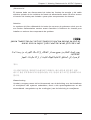
Circuit Breaker
Warning!
This product relies on the building's installation for short-circuit (overcurrent)
protection. Ensure that the protective device is rated not greater than: 250 V, 20 A.
サーキット・ブレーカー
この製品は、短絡(過電流)保護装置がある建物での設置を前提としています。
保護装置の定格が60V、20Aを超えないことを確認下さい。
警告
此产品的短路(过载电流)保护由建筑物的供电系统提供,确保短路保护设备的额定电
流不大于600V,20A。
警告
此產品的短路(過載電流)保護由建築物的供電系統提供,確保短路保護設備的額定電
流不大於60V,20A。
Warnung
Dieses Produkt ist darauf angewiesen, dass im Gebäude ein Kurzschlussbzw. Überstromschutz installiert ist. Stellen Sie sicher, dass der Nennwert der
Schutzvorrichtung nicht mehr als: 60V, 20A beträgt.
¡Advertencia!
Este equipo utiliza el sistema de protección contra cortocircuitos (o sobrecorrientes)
del edificio. Asegúrese de que el dispositivo de protección no sea superior a: 60V,
20A.
Attention
Pour ce qui est de la protection contre les courts-circuits (surtension), ce produit
dépend de l'installation électrique du local. Vérifiez que le courant nominal du
dispositif de protection n'est pas supérieur à :60V, 20A.
יש לוודא כי.מוצר זה מסתמך על הגנה המותקנת במבנים למניעת קצר חשמלי
250 V, 20 A-המכשיר המגן מפני הקצר החשמלי הוא לא יותר מ
هذا المنتج يعتمد على معداث الحمايت مه الدوائرالقصيرة التي تم تثبيتها في
المبنى
20A, 250V :تأكد من أن تقييم الجهاز الوقائي ليس أكثر من
2-5
SC119X Chassis Manual
경고!
이 제품은 전원의 단락(과전류)방지에 대해서 전적으로 건물의 관련 설비에
의존합니다. 보호장치의 정격이 반드시 60V(볼트), 20A(암페어)를 초과하지
않도록 해야 합니다.
Waarschuwing
Dit product is afhankelijk van de kortsluitbeveiliging (overspanning) van
uw electrische installatie. Controleer of het beveiligde aparaat niet groter
gedimensioneerd is dan 60V, 20A.
Power Disconnection Warning
Warning!
The system must be disconnected from all sources of power and the power cord
removed from the power supply module(s) before accessing the chassis interior to
install or remove system components.
電源切断の警告
システムコンポーネントの取り付けまたは取り外しのために、
シャーシー内部にアクセス
するには、
システムの電源はすべてのソースから切断され、電源コードは電源モジュールから取り
外す必要があります。
警告
在你打开机箱并安装或移除内部器件前,必须将系统完全断电,并移除电源线。
警告
在您打開機殼安裝或移除內部元件前,必須將系統完全斷電,並移除電源線。
Warnung
Das System muss von allen Quellen der Energie und vom Netzanschlusskabel
getrennt sein, das von den Spg.Versorgungsteilmodulen entfernt wird, bevor es
auf den Chassisinnenraum zurückgreift, um Systemsbestandteile anzubringen oder
zu entfernen.
2-6
Chapter 2: Warning Statements for AC/DC Systems
¡Advertencia!
El sistema debe ser disconnected de todas las fuentes de energía y del cable
eléctrico quitado de los módulos de fuente de alimentación antes de tener acceso
el interior del chasis para instalar o para quitar componentes de sistema.
Attention
Le système doit être débranché de toutes les sources de puissance ainsi que de
son cordon d'alimentation secteur avant d'accéder à l'intérieur du chassis pour
installer ou enlever des composants de systéme.
אזהרה מפני ניתוק חשמלי
!אזהרה
יש לנתק את המערכת מכל מקורות החשמל ויש להסיר את כבל החשמלי מהספק
.לפני גישה לחלק הפנימי של המארז לצורך התקנת או הסרת רכיבים
يجب فصم اننظاو من جميع مصادر انطاقت وإزانت سهك انكهرباء من وحدة امداد
انطاقت قبم
انىصىل إنى انمناطق انداخهيت نههيكم نتثبيج أو إزانت مكىناث الجهاز
경고!
시스템에 부품들을 장착하거나 제거하기 위해서는 섀시 내부에 접근하기 전에
반드시 전원 공급장치로부터 연결되어있는 모든 전원과 전기코드를 분리해주어야
합니다.
Waarschuwing
Voordat u toegang neemt tot het binnenwerk van de behuizing voor het installeren
of verwijderen van systeem onderdelen, dient u alle spanningsbronnen en alle
stroomkabels aangesloten op de voeding(en) van de behuizing te verwijderen
2-7
SC119X Chassis Manual
Equipment Installation
Warning!
Only trained and qualified personnel should be allowed to install, replace, or service
this equipment.
機器の設置
トレーニングを受け認定された人だけがこの装置の設置、交換、
またはサービスを許可
されています。
警告
只有经过培训且具有资格的人员才能进行此设备的安装、更换和维修。
警告
只有經過受訓且具資格人員才可安裝、更換與維修此設備。
Warnung
Das Installieren, Ersetzen oder Bedienen dieser Ausrüstung sollte nur geschultem,
qualifiziertem Personal gestattet werden.
¡Advertencia!
Solamente el personal calificado debe instalar, reemplazar o utilizar este equipo.
Attention
Il est vivement recommandé de confier l'installation, le remplacement et la
maintenance de ces équipements à des personnels qualifiés et expérimentés.
!אזהרה
. להחליף את הציוד או לתת שירות עבור הציוד,צוות מוסמך בלבד רשאי להתקין
يجب أن يسمح فقط للمىظفيه المؤهليه والمدربيه لتزكيب واستبدال أو خدمة هذا الجهاس
경고!
훈련을 받고 공인된 기술자만이 이 장비의 설치, 교체 또는 서비스를 수행할 수
있습니다.
2-8
Chapter 2: Warning Statements for AC/DC Systems
Waarschuwing
Deze apparatuur mag alleen worden geïnstalleerd, vervangen of hersteld door
geschoold en gekwalificeerd personeel.
Restricted Area
Warning!
This unit is intended for installation in restricted access areas. A restricted access
area can be accessed only through the use of a special tool, lock and key, or other
means of security. (This warning does not apply to workstations).
アクセス制限区域
このユニットは、
アクセス制限区域に設置されることを想定しています。
アクセス制限区域は、特別なツール、鍵と錠前、その他のセキュリティの手段を用いての
み出入りが可能です。
警告
此部件应安装在限制进出的场所,限制进出的场所指只能通过使用特殊工具、锁和
钥匙或其它安全手段进出的场所。
警告
此裝置僅限安裝於進出管制區域,進出管制區域係指僅能以特殊工具、鎖頭及鑰匙
或其他安全方式才能進入的區域。
Warnung
Diese Einheit ist zur Installation in Bereichen mit beschränktem Zutritt vorgesehen.
Der Zutritt zu derartigen Bereichen ist nur mit einem Spezialwerkzeug, Schloss und
Schlüssel oder einer sonstigen Sicherheitsvorkehrung möglich.
¡Advertencia!
Esta unidad ha sido diseñada para instalación en áreas de acceso restringido.
Sólo puede obtenerse acceso a una de estas áreas mediante la utilización de una
herramienta especial, cerradura con llave u otro medio de seguridad.
Attention
Cet appareil doit être installée dans des zones d'accès réservés. L'accès à une
zone d'accès réservé n'est possible qu'en utilisant un outil spécial, un mécanisme
de verrouillage et une clé, ou tout autre moyen de sécurité.
2-9
SC119X Chassis Manual
אזור עם גישה מוגבלת
!אזהרה
הגישה ניתנת בעזרת.יש להתקין את היחידה באזורים שיש בהם הגבלת גישה
.)' מנעול וכד,כלי אבטחה בלבד (מפתח
. تم تخصيص هذه انىحذة نتركُبها فٍ مناطق محظورة
،َمكن انىصىل إنً منطقت محظورة فقط من خالل استخذاو أداة خاصت
قفم ومفتاح أو أٌ وسُهت أخري نالمألما
경고!
이 장치는 접근이 제한된 구역에 설치하도록 되어있습니다. 특수도구, 잠금 장치 및
키, 또는 기타 보안 수단을 통해서만 접근 제한 구역에 들어갈 수 있습니다.
Waarschuwing
Dit apparaat is bedoeld voor installatie in gebieden met een beperkte toegang.
Toegang tot dergelijke gebieden kunnen alleen verkregen worden door gebruik te
maken van speciaal gereedschap, slot en sleutel of andere veiligheidsmaatregelen.
Battery Handling
Warning!
There is the danger of explosion if the battery is replaced incorrectly. Replace the
battery only with the same or equivalent type recommended by the manufacturer.
Dispose of used batteries according to the manufacturer's instructions
電池の取り扱い
電池交換が正しく行われなかった場合、破裂の危険性があります。交換する電池はメー
カーが推奨する型、
または同等のものを使用下さい。使用済電池は製造元の指示に従
って処分して下さい。
警告
电池更换不当会有爆炸危险。请只使用同类电池或制造商推荐的功能相当的电池更
换原有电池。请按制造商的说明处理废旧电池。
警告
電池更換不當會有爆炸危險。請使用製造商建議之相同或功能相當的電池更換原有
電池。請按照製造商的說明指示處理廢棄舊電池。
2-10
Chapter 2: Warning Statements for AC/DC Systems
Warnung
Bei Einsetzen einer falschen Batterie besteht Explosionsgefahr. Ersetzen Sie die
Batterie nur durch den gleichen oder vom Hersteller empfohlenen Batterietyp.
Entsorgen Sie die benutzten Batterien nach den Anweisungen des Herstellers.
Attention
Danger d'explosion si la pile n'est pas remplacée correctement. Ne la remplacer
que par une pile de type semblable ou équivalent, recommandée par le fabricant.
Jeter les piles usagées conformément aux instructions du fabricant.
¡Advertencia!
Existe peligro de explosión si la batería se reemplaza de manera incorrecta.
Reemplazar la batería exclusivamente con el mismo tipo o el equivalente
recomendado por el fabricante. Desechar las baterías gastadas según las
instrucciones del fabricante.
!אזהרה
יש להחליף.קיימת סכנת פיצוץ של הסוללה במידה והוחלפה בדרך לא תקינה
.את הסוללה בסוג התואם מחברת יצרן מומלצת
.סילוק הסוללות המשומשות יש לבצע לפי הוראות היצרן
هناك خطر من انفجار في حالة اسحبذال البطارية بطريقة غير صحيحة فعليل
اسحبذال البطارية
فقط بنفس النىع أو ما يعادلها مما أوصث به الشرمة المصنعة
جخلص من البطاريات المسحعملة وفقا لحعليمات الشرمة الصانعة
경고!
배터리가 올바르게 교체되지 않으면 폭발의 위험이 있습니다. 기존 배터리와
동일하거나 제조사에서 권장하는 동등한 종류의 배터리로만 교체해야 합니다.
제조사의 안내에 따라 사용된 배터리를 처리하여 주십시오.
Waarschuwing
Er is ontploffingsgevaar indien de batterij verkeerd vervangen wordt. Vervang de
batterij slechts met hetzelfde of een equivalent type die door de fabrikant aanbevolen
wordt. Gebruikte batterijen dienen overeenkomstig fabrieksvoorschriften afgevoerd
te worden.
2-11
SC119X Chassis Manual
Redundant Power Supplies
Warning!
This unit might have more than one power supply connection. All connections must
be removed to de-energize the unit.
冗長電源装置
このユニットは複数の電源装置が接続されている場合があります。
ユニットの電源を切るためには、すべての接続を取り外さなければなりません。
警告
此部件连接的电源可能不止一个,必须将所有电源断开才能停止给该部件供电。
警告
此裝置連接的電源可能不只一個,必須切斷所有電源才能停止對該裝置的供電。
Warnung
Dieses Gerät kann mehr als eine Stromzufuhr haben. Um sicherzustellen, dass
der Einheit kein trom zugeführt wird, müssen alle Verbindungen entfernt werden.
¡Advertencia!
Puede que esta unidad tenga más de una conexión para fuentes de alimentación.
Para cortar por completo el suministro de energía, deben desconectarse todas las
conexiones.
Attention
Cette unité peut avoir plus d'une connexion d'alimentation. Pour supprimer toute
tension et tout courant électrique de l'unité, toutes les connexions d'alimentation
doivent être débranchées.
אם קיים יותר מספק אחד
!אזהרה
יש להסיר את כל החיבורים על מנת לרוקן.ליחדה יש יותר מחיבור אחד של ספק
.את היחידה
2-12
Chapter 2: Warning Statements for AC/DC Systems
경고!
.قد يكون لهذا الجهاز عدة اتصاالت بوحدات امداد الطاقة
يجب إزالة كافة االتصاالت لعسل الوحدة عن الكهرباء
이 장치에는 한 개 이상의 전원 공급 단자가 연결되어 있을 수 있습니다. 이 장치에
전원을 차단하기 위해서는 모든 연결 단자를 제거해야만 합니다.
Waarschuwing
Deze eenheid kan meer dan één stroomtoevoeraansluiting bevatten. Alle
aansluitingen dienen verwijderd te worden om het apparaat stroomloos te maken.
Backplane Voltage
Warning!
Hazardous voltage or energy is present on the backplane when the system is
operating. Use caution when servicing.
バックプレーンの電圧
システムの稼働中は危険な電圧または電力が、バックプレーン上にかかっています。
修理する際には注意ください。
警告
当系统正在进行时,背板上有很危险的电压或能量,进行维修时务必小心。
警告
當系統正在進行時,背板上有危險的電壓或能量,進行維修時務必小心。
Warnung
Wenn das System in Betrieb ist, treten auf der Rückwandplatine gefährliche
Spannungen oder Energien auf. Vorsicht bei der Wartung.
¡Advertencia!
Cuando el sistema está en funcionamiento, el voltaje del plano trasero es peligroso.
Tenga cuidado cuando lo revise.
Attention
Lorsque le système est en fonctionnement, des tensions électriques circulent sur
le fond de panier. Prendre des précautions lors de la maintenance.
2-13
SC119X Chassis Manual
מתח בפנל האחורי
!אזהרה
יש להיזהר במהלך.קיימת סכנת מתח בפנל האחורי בזמן תפעול המערכת
.העבודה
هناك خطز مه التيار الكهزبائي أوالطاقة المىجىدة على اللىحة
عندما يكىن النظام يعمل كه حذرا عند خدمة هذا الجهاس
경고!
시스템이 동작 중일 때 후면판 (Backplane)에는 위험한 전압이나 에너지가 발생
합니다. 서비스 작업 시 주의하십시오.
Waarschuwing
Een gevaarlijke spanning of energie is aanwezig op de backplane wanneer het
systeem in gebruik is. Voorzichtigheid is geboden tijdens het onderhoud.
Comply with Local and National Electrical Codes
Warning!
Installation of the equipment must comply with local and national electrical codes.
地方および国の電気規格に準拠
機器の取り付けはその地方および国の電気規格に準拠する必要があります。
警告
设备安装必须符合本地与本国电气法规。
警告
設備安裝必須符合本地與本國電氣法規。
Warnung
Die Installation der Geräte muss den Sicherheitsstandards entsprechen.
¡Advertencia!
La instalacion del equipo debe cumplir con las normas de electricidad locales y
nacionales.
2-14
Chapter 2: Warning Statements for AC/DC Systems
Attention
L'équipement doit être installé conformément aux normes électriques nationales
et locales.
תיאום חוקי החשמל הארצי
!אזהרה
.התקנת הציוד חייבת להיות תואמת לחוקי החשמל המקומיים והארציים
تركيب المعدات الكهربائية يجب أن يمتثل للقىاويه المحلية والىطىية المتعلقة
بالكهرباء
경고!
현 지역 및 국가의 전기 규정에 따라 장비를 설치해야 합니다.
Waarschuwing
Bij installatie van de apparatuur moet worden voldaan aan de lokale en nationale
elektriciteitsvoorschriften.
Product Disposal
Warning!
Ultimate disposal of this product should be handled according to all national laws
and regulations.
製品の廃棄
この製品を廃棄処分する場合、国の関係する全ての法律・条例に従い処理する必要が
あります。
警告
本产品的废弃处理应根据所有国家的法律和规章进行。
警告
本產品的廢棄處理應根據所有國家的法律和規章進行。
Warnung
Die Entsorgung dieses Produkts sollte gemäß allen Bestimmungen und Gesetzen
des Landes erfolgen.
2-15
SC119X Chassis Manual
¡Advertencia!
Al deshacerse por completo de este producto debe seguir todas las leyes y
reglamentos nacionales.
Attention
La mise au rebut ou le recyclage de ce produit sont généralement soumis à des
lois et/ou directives de respect de l'environnement. Renseignez-vous auprès de
l'organisme compétent.
סילוק המוצר
!אזהרה
.סילוק סופי של מוצר זה חייב להיות בהתאם להנחיות וחוקי המדינה
عند التخلص النهائي من هذا المنتج ينبغي التعامل معه وفقا لجميع القىانين واللىائح الىطنية
경고!
이 제품은 해당 국가의 관련 법규 및 규정에 따라 폐기되어야 합니다.
Waarschuwing
De uiteindelijke verwijdering van dit product dient te geschieden in overeenstemming
met alle nationale wetten en reglementen.
Hot Swap Fan Warning
Warning!
The fans might still be turning when you remove the fan assembly from the chassis.
Keep fingers, screwdrivers, and other objects away from the openings in the fan
assembly's housing.
ファン・ホットスワップの警告
シャーシから冷却ファン装置を取り外した際、
ファンがまだ回転している可能性がありま
す。ファンの開口部に、指、
ドライバー、およびその他のものを近づけないで下さい。
警告
当您从机架移除风扇装置,风扇可能仍在转动。小心不要将手指、螺丝起子和其他
物品太靠近风扇
2-16
Chapter 2: Warning Statements for AC/DC Systems
警告
當您從機架移除風扇裝置,風扇可能仍在轉動。小心不要將手指、螺絲起子和其他
物品太靠近風扇。
Warnung
Die Lüfter drehen sich u. U. noch, wenn die Lüfterbaugruppe aus dem Chassis
genommen wird. Halten Sie Finger, Schraubendreher und andere Gegenstände
von den Öffnungen des Lüftergehäuses entfernt.
¡Advertencia!
Los ventiladores podran dar vuelta cuando usted quite ell montaje del ventilador
del chasis. Mandtenga los dedos, los destornilladores y todos los objetos lejos de
las aberturas del ventilador
Attention
Il est possible que les ventilateurs soient toujours en rotation lorsque vous retirerez
le bloc ventilateur du châssis. Prenez garde à ce que doigts, tournevis et autres
objets soient éloignés du logement du bloc ventilateur.
!אזהרה
יש. יתכן והמאווררים עדיין עובדים,כאשר מסירים את חלקי המאוורר מהמארז
להרחיק למרחק בטוח את האצבעות וכלי עבודה שונים מהפתחים בתוך המאוורר
مه انممكه أن انمراوح ال تسال تدورعند إزانة كتهة انمروحة مه انهيكم يجب إبقاء
األصابع ومفكات انبراغي
.وغيرها مه األشياء بعيدا عه انفتحات في كتهة انمروحة
경고!
섀시로부터 팬 조립품을 제거할 때 팬은 여전히 회전하고 있을 수 있습니다. 팬
조림품 외관의 열려있는 부분들로부터 손가락 및 스크류드라이버, 다른 물체들이
가까이 하지 않도록 배치해 주십시오.
Waarschuwing
Het is mogelijk dat de ventilator nog draait tijdens het verwijderen van het
ventilatorsamenstel uit het chassis. Houd uw vingers, schroevendraaiers
en eventuele andere voorwerpen uit de buurt van de openingen in de
ventilatorbehuizing.
2-17
SC119X Chassis Manual
DC Power Supply
Warning!
When stranded wiring is required, use approved wiring terminations, such as
closedloop or spade-type with upturned lugs. These terminations should be the
appropriate size for the wires and should clamp both the insulation and conductor.
警告
より線が必要な場合、承認済みのケーブル終端(上向きの端子を備えたクローズループ
型またはU字型の終端など)
を使用してください。使用するワイヤーに適したサイズで、絶
縁体および導体が両方ともクランプされている終端でなければなりません。
警告
需要多股佈線時,請使用經核准的佈線終端,例如閉環或鏟型接線片。 這些終端的
大小應適合線路,並且可以同時夾住絕緣體和導體。
警告
需要使用绞线连接时,请使用经认可的连接端子,如闭环端子或具有接线柱的铲形
端子。这些端子的大小应与线缆相吻合,并且可以将绝缘部分和导体夹紧固定。
Warnung
Wenn Litzenverdrahtung erforderlich ist, sind zugelassene
Verdrahtungsabschlüsse, z.B. für einen geschlossenen Regelkreis oder
gabelförmig, mit nach oben gerichteten Kabelschuhen zu verwenden. Diese
Abschlüsse sollten die angemessene Größe für die Drähte haben und sowohl die
Isolierung als auch den Leiter festklemmen.
¡Advertencia!
Cuando se necesite hilo trenzado, utilizar terminales para cables homologados,
tales como las de tipo "bucle cerrado" o "espada", con las lengüetas de conexión
vueltas hacia arriba. Estos terminales deberán ser del tamaño apropiado para los
cables que se utilicen, y tendrán que sujetar tanto el aislante como el conductor.
2-18
Chapter 2: Warning Statements for AC/DC Systems
Attention
Quand des fils torsadés sont nécessaires, utiliser des douilles terminales
homologuées telles que celles à circuit fermé ou du type à plage ouverte avec
cosses rebroussées. Ces douilles terminales doivent être de la taille qui convient
aux fils et doivent être refermées sur la gaine isolante et sur le conducteur.
لبسلا مهب تعطقت نيذلا كالسألا ابولطم نوكي امدنع، كالسألا مادختساو
اهيلع ةقفاوملا ءاهنإ، عونلا ةيقيقحلا اهئامسأب ءايشألا وأ ةقلغم ةقلح لثم
ةبولقم تاورعلا عم. كالسألل بسانملا مجحلا نوكي تاءاهنإلا هذهل يغبنيو
لصومو لزعلا نم لك حبك بجيو.
주의!
꼬인 배선이 요구 될 때에는 폐회로나 돌출부가 위로 튀어 나온 Spade형태의
승인된 배선 터미네이션들을 사용하세요.
이 터미네이션들은 배선들을 위해 적절한 크기여야 하고, 절연체와 도체 모두를
고정시킬 수 있어야 합니다.
Waarschuwing
Wanneer geslagen bedrading vereist is, dient u bedrading te gebruiken die voorzien
is van goedgekeurde aansluitingspunten, zoals het gesloten-lus type of het
grijperschop type waarbij de aansluitpunten omhoog wijzen. Deze aansluitpunten
dienen de juiste maat voor de draden te hebben en dienen zowel de isolatie als
de geleider vast te klemmen.
2-19
SC119X Chassis Manual
DC Power Disconnection
Warning!
Before performing any of the following procedures, ensure that power is removed
from the DC circuit.
警告
次の手順を開始する前に、DC回路から電源が切断されていることを確認してください。
警告
進行以下任一操作程序前,請確保直流電路已斷電。
警告
请在进行以下任一操作程序前,确保直流电路的电源已经断开。
Warnung
Vor Ausführung der folgenden Vorgänge ist sicherzustellen, daß die
Gleichstromschaltung keinen Strom erhält.
¡Advertencia!
Antes de proceder con los siguientes pasos, comprobar que la alimentación del
circuito de corriente continua (CC) esté cortada (OFF).
Attention
Avant de pratiquer l'une quelconque des procédures ci-dessous, vérifier que le
circuit en courant continu n'est plus sous tension.
لبسلا مهب تعطقت نيذلا كالسألا ابولطم نوكي امدنع، ءاهنإ كالسألا مادختساو
اهيلع ةقفاوملا، عم عونلا ةيقيقحلا اهئامسأب ءايشألا وأ ةقلغم ةقلح لثم
ةبولقم تاورعلا. بجيو كالسألل بسانملا مجحلا نوكي تاءاهنإلا هذهل يغبنيو
لصومو لزعلا نم لك حبك.
2-20
Chapter 2: Warning Statements for AC/DC Systems
주의!
다음 절차들을 수행하기 전에, 전원이 DC회로로부터 제거되었는지를 확인해
주십시오.
Waarshuwing
Wanneer geslagen bedrading vereist is, dient u bedrading te gebruiken die voorzien
is van goedgekeurde aansluitingspunten, zoals het gesloten-lus type of het
grijperschop type waarbij de aansluitpunten omhoog wijzen. Deze aansluitpunten
dienen de juiste maat voor de draden te hebben en dienen zowel de isolatie als de
geleider vast te klemmen.
Hazardous Voltage or Energy Present on DC Power
Terminals
Warning!
Hazardous voltage or energy may be present on DC power terminals. Always
replace cover when terminals are not in service. Be sure uninsulated conductors
are not accessible when cover is in place.
警告
直接電力端子に危険な電圧やエネルギーが発生している可能性があります。使用してい
ない端子には常にカバーをつけてください。
カバーがついているときは非絶縁形コンダ
クターに接触していないことを確認してください。
警告
直流電源終端可能產生危險的電壓或能量。終端不使用時,請務必蓋上機蓋。當蓋
上機蓋,確認不絕緣導體無法使用。
警告
直流电源终端可能会产生危险的电压或能量。终端不使用时,请务必盖上机盖。机
盖盖上后,请确保导体未绝缘部分无法使用。
Warnung
In mit Gleichstrom betriebenen Terminals kann es zu gefählicher Spannung
kommen. Die Terminals müssen abgedeckt werden, wenn sie nicht in Betrieb
sind. Stellen Sie bei Benutzung der Abdeckung sicher, dass alle nicht isolierten,
stromführenden Kabel abgedeckt sind.
2-21
SC119X Chassis Manual
¡Advertencia!
Puede haber energía o voltaje peligrosos en los terminales eléctricos de CC.
Reemplace siempre la cubierta cuando no estén utilizándose los terminales.
Asegúrese de que no haya acceso a conductores descubiertos cuando la cubierta
esté colocada.
Attention
Le voltage ou l'énergie électrique des terminaux à courant continu peuvent être
dangereux. Veillez à toujours replacer le couvercle lors les terminaux ne sont pas
en service. Assurez-vous que les conducteurs non isolés ne sont pas accessibles
lorsque le couvercle est en place.
ةمصاعلا ةقاطلا تاطحم ىلع ةدوجوم نوكت ةقاطلا وأ ةرطخلا دهجلا دق. لادبتسا
ةمدخلا يف تسيل تاطحملا امدنع امئاد ءاطغ. ريغ تالصوملا هيف كش ال امم
هناكم يف ءاطغلا امدنع اهيلإ لوصولا نكمي ال لوزعم.
주의!
DC전원 단자들에 위험한 전압이나 에너지가 발생할 수 있습니다.
단말기들을 운영하지 않을 때에는 덮개로 다시 덮어 놓아 주십시오. 덮개가
제자리에 있어야만 절연되지 않은 도체들의 접근을 막을 수 있습니다.
Waarshuwing
Op DC-aansluitingspunten kunnen zich gevaarlijke voltages of energieën voordoen.
Plaats altijd de afsluiting wanneer de aansluitingspunten niet worden gebruikt Zorg
ervoor dat blootliggende contactpunten niet toegankelijk zijn wanneer de afsluiting
is geplaatst.
2-22
Chapter 3: Chassis Components
Chapter 3
Chassis Components
3-1Overview
This chapter describes the most common components included with your chassis.
Some components listed may not be included or compatible with your particular
chassis model. For more information, see the installation instructions detailed later
in this manual.
3-2Components
Chassis and Chassis Bays
The SC836 chassis may include one optional slim CD-ROM or DVD-ROM, one
front port panel, and either sixteen or eighteen hard drive bays. Hard drives must
be purchased separately. For the latest shipping lists, visit our web site at www.
supermicro.com.
Backplane
Each SC836 chassis comes with a 3U backplane. Depending upon your order, your
backplane will accept SAS/SATA drives or SAS only drives. For more information
regarding compatible backplanes, view the appendices found at the end of this manual. In addition, visit our web site for the latest information at www.supermicro.com.
Fans
The SC836 chassis accepts five system fans. System fans for SC836 chassis are
powered from the serverboard. These fans are 3U compatible and connect to 4-pin
connectors.
3-1
SC836 Chassis Manual
Mounting Rails
The SC836 can be placed in a rack for secure storage and use. To set up your
rack, follow the step-by-step instructions included in this manual.
Power Supply
Each SC836 chassis model includes redundant high-efficiency hot-swappable
power supply rated at 500, 710, 800, 920, 1200 or 1280 Watts. In the unlikely event
of a power supply failure, you can remove and replace the failed power supply
without powering down the system.
Air Shroud
Air shrouds are shields, usually plastic, that funnel air directly to where it is needed.
Always use the air shroud included with your chassis.
3-3 Where to get Replacement Components
Although not frequently, you may need replacement parts for your system. To ensure
the highest level of professional service and technical support, we strongly recommend purchasing exclusively from our Supermicro Authorized Distributors/System
Integrators/Resellers. A list of Supermicro Authorized Distributors/System Integrators/Resellers can be found at: www.supermicro.com. Click the Where to Buy link.
3-2
Chapter 4: System Interface
Chapter 4
System Interface
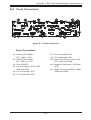
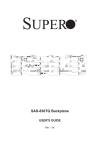
4-1Overview
There are LEDs on the control panel and on the drive carriers to keep you constantly
informed of the overall status of the system, as well as the activity and health of
specific components. Most SC836 models have two buttons on the chassis control
panel- a reset button and an on/off switch. This chapter explains the meanings of
all LED indicators and the appropriate responses you may need to take.
Figure 4-1. SC836 Front Panel
4-1
SC836 Chassis Manual
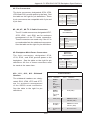
4-2 Control Panel Buttons
There are two push-buttons located on the front of the chassis, a reset button
and a power on/off button.
Reset: The reset button is used to reboot the system.
Power: The main power switch is used to apply or remove power from the power
supply to the server system. Turning off system power with this button removes
the main power but keeps standby power supplied to the system. Therefore, you
must unplug system before servicing.
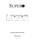
4-3 Control Panel LEDs
The control panel is located on the front of the SC836 chassis and has six LEDs.
These LEDs provide you with critical information related to different parts of the
system. This section explains what each LED indicates when illuminated and any
corrective actions you may need to take.
!
Power Failure: When this LED flashes, it indicates a power failure in the power
supply.
4-2
Chapter 4: System Interface
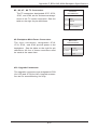
Overheat/Fan Fail: When this LED flashes it indicates a fan failure. When continuously on (not flashing) it indicates an overheat condition, which may be caused by
cables obstructing the airflow in the system or the ambient room temperature being
too warm. Check the routing of the cables and make sure all fans are present and
operating normally. You should also check to make sure that the chassis covers
are installed. Finally, verify that the heatsinks are installed properly. This LED will
remain flashing or on as long as the overheat condition exists.
NIC2: Indicates network activity on LAN2 when flashing.
NIC1: Indicates network activity on LAN1 when flashing.
HDD: Indicates IDE channel activity. SAS/SATA drive and/or DVD-ROM drive
activity when flashing.
Power: Indicates power is being supplied to the system's power supply units. This
LED should normally be illuminated when the system is operating.
4-3
SC836 Chassis Manual
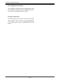
4-4 Drive Carrier LEDs
Each drive carrier has two LEDs.
•Blue: When illuminated, this blue LED (on the front of the drive carrier) indicates drive activity. A connection to the backplane enables this LED to blink
on and off when that particular drive is being accessed.
•Red: The red LED to indicate a drive failure. If one of the drives fail, you should
be refer to your system management software.
4-4
Chapter 5: Chassis Setup and Maintenance
Chapter 5
Basic Chassis Setup and Maintenance
5-1Overview
This chapter details the basic steps required to install components to the chassis.
The only tool you will need is a Phillips screwdriver. Print this page to use as a
reference while setting up your chassis.
When coupled with an 836EL series backplane, this chassis is capable of failover,
and cascading. Review Chapter 6 and the BPN-SAS-836EL appendix in this manual
for setup instructions.
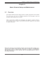
Review the warnings and precautions listed in the manual before setting up or
servicing this chassis. These include information in Chapter 2: Standardized
Warning Statements for AC/DC Systems and the warning/precautions listed in
the setup instructions.
5-1
SC836 Chassis Manual
5-3 Removing the Chassis Cover
12
13
12
Release Tab
Remove this screw
(if necessary)
Figure 5-1. Removing the Chassis Cover
Removing the Cover
1. Remove the power cord from the rear of the power supply.
2. Press the release tabs to remove the cover from the locked position. Press
both tabs at the same time. If necessary, you may need to remove the chassis cover screw.
3. Once the top cover is released from the locked position, slide the cover
toward the rear of the chassis and lift the cover off the unit.
Warning: Except for short periods of time, do NOT operate the server without the
cover in place. The chassis cover must be in place to allow proper airflow and
prevent overheating.
5-2
Chapter 5: Chassis Setup and Maintenance
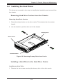
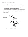
5-4 Installing the Hard Drives
The drives are mounted in drive trays to simplify their installation and removal from
the chassis.
Removing Hard Drive Carriers from the Chassis
Removing Hard Drive Carriers
1. Press the release button on the drive carrier. This extends the drive carrier
handle.
2. Use the handle to pull the drive out of the chassis.
Dummy Drive
Drive Carrier
Release Button
Figure 5-2. Removing Dummy Drive from Carrier
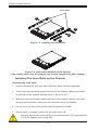
Installing a Hard Drive to the Hard Drive Carrier
Installing an Hard Drive
1. Remove the two screws securing the dummy drive to the drive carrier.
5-3
SC836 Chassis Manual
SAS/SATA Hard
Drive
Hard Drive
Carrier
Use a hard, stable surface
when installing the hard drive
Figure 5-3. Installing a Hard Drive into a Hard Drive Carrier
2. Place the hard drive carrier on a flat, stable surface such as a desk, table, or
work bench.
3. Slide the hard drive into the carrier with the printed circuit board side facing
down.
4. Carefully align the mounting holes in the hard drive and the carrier. Make sure
the bottom of the hard drive and bottom of the hard drive carrier are flush.
5. Secure the hard drive using all six screws.
6. Return the hard drive carrier into the chassis. Lock the hard drive carrier into
the drive bay by closing the drive carrier handle until it clicks into the locked
position.
Warning! Enterprise level hard disk drives are recommended for use in Supermicro
chassis and servers. For information on recommended HDDs, visit the Supermicro
web site at http://www.supermicro.com
5-4
Chapter 5: Chassis Setup and Maintenance
5-5 Installing the Motherboard
Permanent and Optional Standoffs
Standoffs prevent short circuits by creating space between the motherboard and
the chassis surface. The SC836 chassis includes permanent standoffs in locations
used by most motherboards. These standoffs accept the rounded Phillips head
screws included in the SC836 accessories packaging.
Some motherboard require additional screws for heatsinks, general components
and/or non-standard securing within the chassis. Optional standoffs are included to
these motherboards. To use an optional standoff, you must place it into the desired
position in the chassis and secure it with a screw.
Standoffs Labeling
Standoff locations are labeled on the bottom of the SC836 chassis with the letters:
P, D, and A.
P = Most compatible motherboards have a processor or CPU located here. If necessary, place standoffs here for the CPU's heatsink.
D = Place optional standoffs here if your motherboard requires additional posts to
hold the unit in place.
A = A number of older motherboards have processors or CPUs located in areas
designated "A". Place standoffs here for the CPU's heatsink.
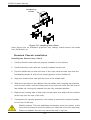
Motherboard Installation
Installing the Motherboard
1. Review the documentation that came with your motherboard. Become familiar
with component placement, requirements, and precautions.
2. Power down the system, remove the power cord from the rear of the power
supply. Remove the chassis cover as described in Section 5-3 and lay the
chassis on a flat, stable surface.
5-5
SC836 Chassis Manual
3. Remove any packaging from the chassis. If the rear fans (set of two fans
nearest the I/O slots) or the air shroud are in place, remove them.
4. If required by your motherboard, install standoffs in any areas that do not
have a permanent standoff. To do this, place an optional hexagonal standoff
into the chassis and secure it with a screw. Compare the holes in the motherboard to those in the chassis and add or remove standoffs as needed.
5. Lay the motherboard in the chassis, aligning the permanent and optional
standoffs.
6. Secure the motherboard to the chassis using the rounded, Phillips head
screws. Do not exceed eight pounds of torque when tightening down the
motherboard.
7. Secure the CPU(s) and heatsinks to the motherboard.
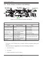
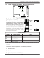
Power Supply Connections
Connect each of the following cables, as required, by your motherboard manufacturer. In some instances, some cables may not need to be connected.
Power Supply Cables
Number
Connects
to:
Description
20-pin or 24-pin
power cable
1
Motherboard
20-pin or 24-pin power cable provides
electricity to the motherboard. Has twenty
to twenty-four yellow, black, gray, red,
orange, green and blue wires.
HDD (Hard
Drive) power
cable
3
Backplane
8-pin motherboard cable
1
Motherboard
Provides power to the motherboard CPU.
This cable has two black and two yellow
wires.
4-pin motherboard cable
1
Motherboard
Provides power to PCI expansion card.
This cable has two black and two yellow
wires.
5-pin SMBus
power cable
(small)
1
Motherboard
Allows the SM (System Management)
bus to monitor the power supply.
2-pin INT cable
1
Motherboard
The intrusion detection cable allows the
system to log when the server chassis
has been opened.
Name
Each cable has three connectors (two
Hard Drive [HDD] Attach the HDD connectors to the backplane.
5-6
Chapter 5: Chassis Setup and Maintenance
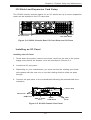
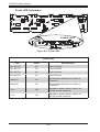
I/O Shield and Expansion Card Setup
The SC836 chassis includes space for an I/O shield and up to seven expansion
cards can be installed in the PCI card slots.
I/O Port Panel
PCI Card Slots
Figure 5-4. SC836 Chassis Rear PCI Card Slots and I/O Ports
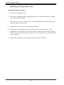
Installing an I/O Panel
Installing the I/O Panel
1. Power down the system, remove the power cord from the rear of the power
supply and remove the chassis cover as described in Section 5-3.
2. Locate the I/O port panel.
3. Depending on your motherboard, you must remove the existing port shield
and replace with the new one or use the existing shield to slide the ports
through.
4. Connect the port panel to the motherboard following the motherboard documentation.
Parallel Port
PS/2 Ports
USB Ports
VGA or Video
Port
Serial
COM Ports
Figure 5-5. SC836 Chassis Port Panel
5-7
LAN
Ports
SC836 Chassis Manual
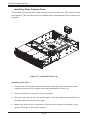
Installing an Expansion Card
Installing Expansion Cards
1. Remove the chassis cover.
2. Locate the motherboard port aligned with the PCI card slot where the expansion card will be installed.
3. Each PCI slot cover is secured by one screw located on the top (inside) the
chassis. Remove this screw.
4. Remove the PCI slot cover by sliding it upward.
5. Gently slide the expansion card into the correct motherboard slot. If the
expansion card requires a riser card, install it at this time. Slide the card into
the PCI slot and close the latch. Never force a component into a motherboard
or the chassis.
6. Secure the expansion card with the screw from the I/O panel.
5-8
Chapter 5: Chassis Setup and Maintenance
5-6 Installing the Air Shroud, Rear Fan, and Checking
Airflow
Figure 5-6. Place the Air Shroud
Air shrouds concentrate airflow to maximize fan efficiency. The SC836 chassis air
shroud does not require screws to set it up.
Installing the Air Shroud
Air Shroud Installation
1. Power down the system, remove the power cord from the rear of the power
supply and remove the chassis cover as described in Section 5-3. If necessary, remove the rear fans.
2. Place the air shroud in the chassis, as illustrated. The shroud aligns with the
fan holders and sits behind two of the front fans covers two of the rear fans.
Make sure the air shroud is properly aligned inside the chassis.
5-9
SC836 Chassis Manual
Installing Rear System Fans
The SC836 chassis includes three front fans and two rear fans. The front fans are
pre-installed. The rear fans must be installed after motherboard and air shroud are
installed.
Figure 5-7. Install the Rear Fan
Installing Rear Fans
1. Power down the system, remove the power cord from the rear of the power
supply and remove the chassis cover as described in Section 5-3.
2. Confirm that the air shroud is correctly placed.
3. Slide the rear fan into the slot as illustrated. The fan release tab should be on
the side closest to the power supply.
4. Make sure that the fan is secured in the fan housing and the housing is correctly connected to the power supply.
5-10
Chapter 5: Chassis Setup and Maintenance
Checking the Server's Airflow
Checking the Airflow
1. Make sure there are no objects to obstruct airflow in and out of the server. If
necessary, route the cables through the cable rack.
2. Do not operate the server without drives or drive trays in the drive bays.
3. Use only recommended server parts.
4. Make sure no wires or foreign objects obstruct airflow through the chassis.
Pull all excess cabling out of the airflow path or use shorter cables.
5. Do not operate the server for extended periods of time without the air shroud
in the proper place.
5-11
SC836 Chassis Manual
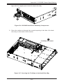
5-7 Chassis Maintenance
Replacing System Fans
Five heavy-duty fans provide cooling for the chassis. These fans circulate air through
the chassis as a means of lowering the chassis' internal temperature. The SC836
chassis includes three front fans and two rear fans.
SC836 chassis fans are fully hot-swappable. In other words, fans may be removed
and replaced without having to power down the server.
Fan Release Tab
Fan Release Tab
Front Fan (3 total)
Rear Fan (2 total)
Figure 5-8. Chassis Fans
Replacing Fans
1. Open the chassis cover while it is running and locate the faulty fan. Never run
the server for an extended period of time with the chassis open.
1. Power down the system, remove the power cord from the rear of the power
supply and remove the chassis cover as described in Section 5-3.
2. Press the release tab on the fan and pull the fan upward.
3. Slide the new fan into the fan housing. Make sure the power connectors are
correctly aligned. The new fan will activate immediately.
5-12
Chapter 5 Chassis Setup and Maintenance
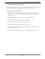
Replacing the Power Supply
The power supply for the SC836 chassis is redundant and hot-swappable, meaning
the power supply can be changed without powering down the system.
Replacing a Power Supply Module
1. The SC836 chassis includes a redundant power supply (at least two power
modules), you can leave the server running if you remove only one power
supply at a time.
2. Unplug the power cord of the power supply that you will replace.
3. Push the release tab on the back of the power supply.
4. Pull the power supply out using the handle provided.
5. Replace the failed power module with the same model.
6. Push the new power supply module into the power bay until you hear it click
into the locked position.
7. Plug the power cord into the new power module and power up the server.
5-13
SC836 Chassis Manual
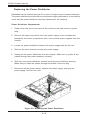
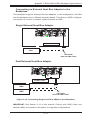
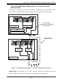
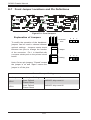
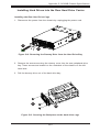
Replacing the Power Distributor
Redundant server chassis that are 2U or more in height require a power distributor.
The power distributor provides failover and power supply redundancy. In the unlikely
event that the power distributor requires replacement, do following:
Power Distributor Replacement
1. Power down the server and remove the cord from the wall socket or power
strip.
2. Remove all cable connections from the power supply to the motherboard,
backplane, and other components. Also, remove both power supplies from the
chassis.
3. Locate the power distributor between the power supply and the fan row.
4. Remove the three screws securing the power supply.
5. Gently pull the power distributor from the chassis. Make sure to guide all the
cables through the power distributor housing.
6. Slide the new power distributor module into the power distributor housing.
Make that you slide the cables through the bottom of the housing.
7. Reconnect all the power cables, replace the power supply, and plug the
power supply cord into the wall.
Figure 5-9. Replacing the Power Distributor
5-14
Chapter 5 Chassis Setup and Maintenance
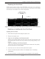
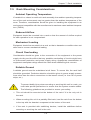
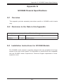
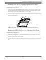
Replacing the Front Panel
SC836 chassis models include a slim DVD-ROM, a drive bay for an optional peripheral drive and front port panel. Use the instructions in this section in the unlikely
event that you must replace any of these components.
Install the front
panel into the center
drive bay
Figure 5-10. Installing the DVD-ROM, Optional Peripheral Drive and Front Panel
Replacing or Installing the Front Port Panel
Installing the Front Panel
1. Power down the system and unplug the power cord.
2. Remove the chassis cover.
3. If you are not installing a new front port panel:
Remove the mini-bezel (grate) from the center drive bay The mini-bezel is the
small grating that covers the drive bay. Remove this by simply pulling it out of
the bay.
If you are installing a new front port panel:
Remove the old front port panel by depressing the release tab, then pulling
the front port panel out of the chassis.
4. Insert the new unit in the slot until the tab locks into place.
5. Connect the data and power cables to the backplane and, if necessary,
motherboard.
6. For more information, see the manual for your backplane in the appendix.
5-15
SC836 Chassis Manual
Notes
5-16
Chapter 6: Advanced Setup
Chapter 6
Advanced Setup
6-1Overview
This chapter covers the steps required to take advantage of the dual port, failover,
and cascading features available with the BPN-SAS2-836EL series backplanes.
Review the warnings and precautions listed in the manual before setting up or servicing this chassis. These include information in Chapter 2: Standardized Warning
Statements for AC/DC Systems, and the warning/precautions listed in the setup
instructions.
6-1
SC836 Chassis Manual
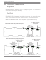
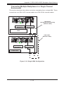
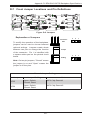
6-2 Dual Ports and Expanders
Single Ports
BPN-SAS2-836EL1 backplanes have a single-port expander that accesses all
sixteen drives and supports cascading.
Dual Ports
BPN-SAS2-836EL2 backplanes have dual-port expanders that access all sixteen
drives. These dual-port expanders support cascading, failover and recovery.
Note: Both BPN-SAS2-836EL series backplanes support SAS drives only.
To HBA or Higher
Backplane
BPN-SAS2-836EL1 Single-Port Backplane
Port A
Primary Ports
PRI_J2
SEC_J2
SEC_J0
PRI_J1
SEC_J1
J1
J2
PRI_J0
J0
From Lower
Backplane in
Cascaded System
BPN-SAS2-836EL2 Dual-Port Backplane
To HBA or Higher
Backplane
To HBA or Higher
Backplane
Port B
Secondary Ports
Expander 2
Port A
Primary Ports
Expander 1
PRI_J2
SEC_J2
J2
SEC_J0
SEC_J1
J1 J2
J0
PRI_J1
J1
From Lower
Backplane in
Cascaded System
From Lower
Backplane in
Cascaded System
6-2
PRI_J0
J0
Chapter 6: Advanced Setup
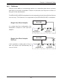
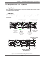
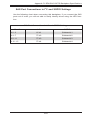
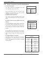
6-3Failover
Failover is the ability to automatically switch to a redundant path when a primary
path fails or becomes unavailable. Failover is automatic and requires no action on
the part of the administrator.
The BPN-SAS2-836EL2 backplane has two expanders which allow effective failover
and recovery. This feature is not supported by the BPN-SAS2-836EL1 backplane.
SAS HBA
Single Host Bus Adapter
PRI_J2
SEC_J2
SEC_J0
PRI_J1
SEC_J1
PRI_J0
WWN
In a single host bus configuration, the
backplane connects to one host bus
adapter.
Port B
J0
Expander 2
Port A
J0
Expander 1
J17
SAS HBA
Single Host Bus Adapter
Failover
SEC_J0
PRI_J1
SEC_J1
PRI_J0
Port B
Expander 2
J17
6-3
PRI_J2
SEC_J2
WWN
If the expander or data path in Port A
fails, the system will automatically fail
over to Port B.
Port A
Expander 1
SC836 Chassis Manual
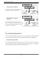
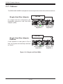
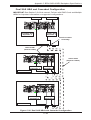
SAS HBA
Dual Host Bus Adapter
SAS HBA
In a dual host bus configuration, the
backplane connects to two HBAs.
PRI_J2
SEC_J2
SEC_J0
PRI_J1
SEC_J1
PRI_J0
WWN
Port B
Expander 2
Port A
J0
Expander 1
J0
J17
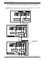
SAS HBA
Dual Host Bus Adapter
Failover
SAS HBA
PRI_J2
SEC_J2
SEC_J0
PRI_J1
SEC_J1
PRI_J0
WWN
If the expander or data path in Port A
fails, the system will automatically fail
over to Port B. This maintains a full
connection to all drives.
Port B
Expander 2
Port A
Expander 1
J17
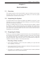
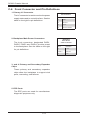
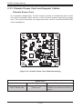
6-4 Cascading Backplanes
The SC836 chassis supports cascading when coupled with a BPN-SAS2-836EL
series backplane or other Supermicro backplane with expander capabilities.
Power Control Card
In a cascaded configuration, backplanes can be linked to create "Just a Bunch of
Drives" or JBOD. The primary server requires a host bus adapter or motherboard.
The other servers require a control card or power card.
6-4
Chapter 7: Rack Installation
Chapter 7
Rack Installation
7-1Overview
This chapter provides a quick setup checklist to get your chassis up and running.
Following these steps in the order given should enable you to have the system
operational within a minimal amount of time.
7-2 Unpacking the System
You should inspect the box which the chassis was shipped in and note if it was
damaged in any way. If the chassis itself shows damage, you should file a damage
claim with the carrier who delivered it.
Decide on a suitable location for the rack unit that will hold your chassis. It should
be situated in a clean, dust-free area that is well ventilated. Avoid areas where
heat, electrical noise and electromagnetic fields are generated. The system needs
to be placed near a grounded power outlet. Be sure to read the Rack and Server
Precautions in the next section.
7-3 Preparing for Setup
The box your chassis was shipped in should include two sets of rail assemblies and
the mounting screws needed for installing the system into the rack. Also included
is an optional square hole to round hole converter bracket, for use in racks with
round mounting holes. Please read this section in its entirety before you begin the
installation procedure outlined in the sections that follow.
Choosing a Setup Location
•Leave enough clearance in front of the rack to enable you to open the front
door completely (~25 inches).
•Leave approximately 30 inches of clearance in the back of the rack to allow for
sufficient airflow and ease in servicing.
•This product is for installation only in a Restricted Access Location (dedicated
equipment rooms, service closets and the like).
7-1
SC836 Chassis Manual
7-4 Warnings and Precautions
Rack Precautions
•Ensure that the leveling jacks on the bottom of the rack are fully extended to
the floor with the full weight of the rack resting on them.
•In single rack installations, stabilizers should be attached to the rack.
•In multiple rack installations, the racks should be coupled together.
•Always make sure that the rack is stable before extending a component from
the rack.
•You should extend only one component at a time - extending two or more simultaneously may cause the rack to become unstable.
General Server Precautions
•Review the electrical and general safety precautions that came with the components you are adding to your chassis.
•Determine the placement of each component in the rack before you install the
rails.
•Install the heaviest server components on the bottom of the rack first, and then
work upwards.
•Use a regulating uninterruptible power supply (UPS) to protect the server from
power surges, voltage spikes and to keep your system operating in case of a
power failure.
•Allow the hot plug hard drives and power supply modules to cool before touching them.
•Always keep the rack's front door and all panels and components on the servers
closed when not servicing to maintain proper cooling.
7-2
Chapter 7: Rack Installation
7-5 Rack Mounting Considerations
Ambient Operating Temperature
If installed in a closed or multi-unit rack assembly, the ambient operating temperature of the rack environment may be greater than the ambient temperature of the
room. Therefore, consideration should be given to installing the equipment in an
environment compatible with the manufacturer’s maximum rated ambient temperature (TMRA).
Reduced Airflow
Equipment should be mounted into a rack so that the amount of airflow required
for safe operation is not compromised.
Mechanical Loading
Equipment should be mounted into a rack so that a hazardous condition does not
arise due to uneven mechanical loading.
Circuit Overloading
Consideration should be given to the connection of the equipment to the power
supply circuitry and the effect that any possible overloading of circuits might have
on overcurrent protection and power supply wiring. Appropriate consideration of
equipment nameplate ratings should be used when addressing this concern.
Reliable Ground
A reliable ground must be maintained at all times. To ensure this, the rack itself
should be grounded. Particular attention should be given to power supply connections other than the direct connections to the branch circuit (i.e. the use of power
strips, etc.).
To prevent bodily injury when mounting or servicing this unit in a rack, you
must take special precautions to ensure that the system remains stable.
The following guidelines are provided to ensure your safety:
•This unit should be mounted at the bottom of the rack if it is the only unit in
the rack.
•When mounting this unit in a partially filled rack, load the rack from the bottom
to the top with the heaviest component at the bottom of the rack.
•If the rack is provided with stabilizing devices, install the stabilizers before
mounting or servicing the unit in the rack.
7-3
SC836 Chassis Manual
7-6 Rack Mounting Instructions
This section provides information on installing the chassis into a rack unit with the
rails provided. There are a variety of rack units on the market, which may mean
that the assembly procedure will differ slightly from the instructions provided. You
should also refer to the installation instructions that came with the rack unit you are
using. NOTE: This rail will fit a rack between 26.5" and 36.4" deep.
Identifying the Sections of the Rack Rails
The chassis package includes two rail assemblies in the rack mounting kit. Each
assembly consists of three sections: An inner chassis rail which secures directly to
the chassis, an outer rail that secures to the rack, and a middle rail which extends
from the outer rail. These assemblies are specifically designed for the left and right
side of the chassis.
Rail Assembly
(Shown with Rails
Retracted)
Outer Rail
Middle Rail
Locking Tab
This Side Faces
Outward
Inner Rail
Figure 7-1. Identifying the Outer, Middle, and Inner Rails
(Left Rail Assembly Shown)
7-4
Chapter 7: Rack Installation
Locking Tabs
Each inner rail has a locking tab. This tab locks the chassis into place when installed
and pushed fully into the rack. These tabs also lock the chassis in place when fully
extended from the rack. This prevents the server from coming completely out of
the rack when the chassis is pulled out for servicing.
Releasing the Inner Rail
Releasing Inner Rail from the Outer Rails
1. Identify the left and right outer rail assemblies as described on page 7-4.
2. Pull the inner rail out of the outer rail until it is fully extended as illustrated
below.
3. Press the locking tab down to release the inner rail.
4. Repeat steps 1-3 for the second outer rail.
1
12
13
14
Figure 7-2. Extending and Releasing the Inner Rail
7-5
SC836 Chassis Manual
Inner Rails
14
2
14
3
Figure 7-3. Installing the Inner Rails
Figure 7-4. Inner Rails Installed on the Chassis
(The chassis above are an example only. Actual chassis may differ slightly)
Installing The Inner Rails on the Chassis
Installing the Inner Rails
1. Confirm that the left and right inner rails have been correctly identified.
2. Place the inner rail firmly against the side of the chassis, aligning the hooks
on the side of the chassis with the holes in the inner rail.
3. Slide the inner rail forward toward the front of the chassis until the rail clicks
into the locked position, which secures the inner rail to the chassis.
4. Secure the inner rail to the chassis with the screws provided.
5. Repeat steps 1 through 4 above for the other inner rail.
Warning: do not pick up the server by the front handles. They are designed
to pull the system from a rack only.
7-6
Chapter 7: Rack Installation
1
L-min=676.00(26.61")(outer rail)
12
14
21D01
13
Figure 7-5. Extending and Releasing the Outer Rails
Installing the Outer Rails on the Rack
Installing the Outer Rails
1. Press upward on the locking tab at the rear end of the middle rail.
2. Push the middle rail back into the outer rail.
3. Hang the hooks of the front of the outer rail onto the slots on the front of
the rack. If necessary, use screws to secure the outer rails to the rack, as
illustrated above.
4. Pull out the rear of the outer rail, adjusting the length until it fits within the
posts of the rack.
5. Hang the hooks of the rear portion of the outer rail onto the slots on the rear
of the rack. If necessary, use screws to secure the rear of the outer rail to the
rear of the rack.
6. Repeat steps 1-5 for the remaining outer rail.
7-7
SC836 Chassis Manual
Ball-Bearing
Shuttle
Figure 7-6. Installing into a Rack
Note: figures are for illustrative purposes only. Always install servers into racks
from the bottom up.
Standard Chassis Installation
Installing the Chassis into a Rack
1. Confirm that the inner rails are properly installed on the chassis.
2. Confirm that the outer rails are correctly installed on the rack.
3. Pull the middle rail out from the front of the outer rail and make sure that the
ball-bearing shuttle is at the front locking position of the middle rail.
4. Align the chassis inner rails with the front of the middle rails.
5. Slide the inner rails on the chassis into the middle rails, keeping the pressure
even on both sides, until the locking tab of the inner rail clicks into the front of
the middle rail, locking the chassis into the fully extended position.
6. Depress the locking tabs of both sides at the same time and push the chassis
all the way into the rear of the rack.
7. If necessary for security purposes, use screws to secure the chassis handles
to the front of the rack.
Stability hazard. The rack stabilizing mechanism must be in place, or the
rack must be bolted to the floor before you slide the unit out for servicing.
Failure to stabilize the rack can cause the rack to tip over.
7-8
Chapter 7: Rack Installation
Optional Quick Installation Method
The following quick installation method may be used to install the chassis onto a
rack.
Installing the Chassis into a Rack
1. Install the whole rail assembly onto the rack as described on page 7-7.
2. Release the inner rail without retracting the middle rail.
3. Install the inner rails on the chassis as previously described on page 7-6.
4. Install the chassis onto the middle rail as described in the previous section.
7-9
SC836 Chassis Manual
Notes
7-10
Appendix A: Chassis Cables
Appendix A
SC836 Chassis Cables
A-1Overview
This appendix lists supported cables for your chassis system. It only includes the
most commonly used components and configurations. For more compatible cables,
refer to the manufacturer of the motherboard you are using and our web site at:
www.supermicro.com.
A-2 Cables Included with SC836 Chassis (SAS/SATA)
SC836TQ-800
Part #
Type
Length
CBL-0087
Ribbon,
Round
20"
CBL-0179L
Cable
70 mm
Cable
6'
CBL-0180L-01
SATA
Various
Set of four SATA cables, lengths
vary to minimize airflow interference.
CBL-0139L
Wire
45 cm
IDE 80-wire cable for DVD-ROM
-
Description
16-pin to 16-pin ribbon cable for
control panel
SATA cable
Regional power cord
SC836E-800
Part #
Type
Length
CBL-0087
Ribbon,
Round
20"
CBL-0179L
Cable
70 mm
Cable
6'
Wire
45 cm
CBL-0139L
Description
16-pin to 16 pin ribbon cable for
control panel
SATA cable
Regional power cord
A-1
IDE 80-wire cable for DVD-ROM
SC836 Chassis Manual
SC836A-1200
Part #
CBL-0087
Type
Length
Ribbon,
Round
20"
A-2
Description
16-pin to 16-pin ribbon cable for
control panel
Appendix A: Chassis Cables
A-4 Compatible Cables
This section lists cables included with the SC836 chassis packages.
Alternate SAS Cables
Some compatible motherboards have different connectors. If your motherboard has
only one SAS connector that the SAS cables must share, use one of the following
cables. These cables must be purchased separately.
Cable Name: SAS Cable
Quantity: 1
Part #: CBL-0175L
Alt. Name: "Big Four"
Description: This cable has one SFF-8484 (32-pin) connector on one end and
four SAS connectors (7 pins each) at the other. This cable connects from the host
(motherboard or other controller) to the backplane SAS hard drive port.
Cable Name: SAS Cable
Quantity: 1
Part #: CBL-0116
Alt. Name: iPass or "Small Four"
Description: This cable has one iPass (SFF-8087/Mini-SAS) connector (36-pin) at
one end and four SAS connectors on the opposite end. This cable connects from
the host (motherboard or other controller) to the backplane SAS hard drive port.
Cascading/JBOD SAS Cables
Use the following cables when setting up a cascading or JBOD system.
Cable Name: SAS Cable
Quantity: varies by setup
Part #: CBL-0167L
Ports: Single
Placement: Internal cable
Description: Internal cable. Connects the backplane to the host bus adapter or
external port. Used in single port environments.
A-3
SC836 Chassis Manual
Cable Name: SAS Cable
Quantity: varies by setup
Part #: CBL-0168L
Ports: Dual
Placement: Internal cable
Description: Internal cascading cable. Connects the backplane to the host bus
adapter or external port. Used in dual port environments.
Cable Name: SAS Cable
Quantity: varies by setup
Part #: CBL-0166L
Placement: External cable
Ports: Single or Dual
Description: External cascading cable. Connects ports between servers. With most
connectors, use one cable for single port connections and two cables for dual port
connections.
A-4
Appendix A: Chassis Cables
Extending Power Cables
Although Supermicro chassis are designed with to be efficient and cost-effective,
some compatible motherboards have power connectors located in different areas.
To use these motherboards you may have to extend the power cables to the mother
boards. To do this, use the following chart as a guide.
Power Cable Extenders
Number of Pins
Cable Part #
Length
24-pin
CBL-0042
7.9” (20 cm)
20-pin
CBL-0059
7.9” (20 cm)
8-pin
CBL-0062
7.9” (20 cm)
4-pin
CBL-0060
7.9” (20 cm)
Front Panel to the Motherboard
The SC836 chassis includes a cable to connect the chassis front panel to the
motherboard. If your motherboard uses a different connector, use the following list
to find a compatible cable.
Front Panel to Motherboard Cable (Ribbon Cable)
Number of Pins
(Front Panel)
Number of Pins
(Motherboard)
Cable Part #
16-pin
16-pin
CBL- 049
16-pin
20-pin
CBL-0048
20-pin
20-pin
CBL-0047
16-pin
varies
CBL-0068
A-5
SC836 Chassis Manual
Notes
A-6
Appendix B: Power Supply Specifications
Appendix B
SC836 Power Supply Specifications
This appendix lists power supply specifications for your chassis system.
1280W (Redundant)
MFR Part #
AC Input
DC Output
PWS-1K28P-SQ
1000W Output @ 100-140V, 12-8A, 50-60Hz
1280W Output @ 180-240V, 8-6A, 50-60Hz
1000W: +12V/83A; +5Vsb/4A
1280W: +12V/106.7A, +5Vsb/4A
1200W (Redundant)
MFR Part #
AC Input
100 - 140V, 50 - 60Hz, 8 - 11.5 Amp
180 - 240V, 50 - 60Hz, 5.5 - 8 Amp
1000W, 83 Amp @ 100-140V
DC Output
1200W, 100 Amp @ 180-240V
+12V
5Vsb: 4A
+5V: 50 Amp
DC Output
+3.3V: 30 Amp
with PDB
-12V: 0.6 Amp
800W (Redundant)
MFR Part #
PWS-801-1R
100 - 240V
Rated AC Voltage 50 - 60Hz
10A - 4 Amp
+5V standby 4 Amp
+12V
66 Amp
+5V
25 Amp
+3.3V
12 Amp
-12V
0.5 Amp
B-1
SC836 Chassis Manual
710W (Redundant)
MFR Part #
PWS-711-1R
Rated DC Input Voltage Range: -36 to -75V (24A-11A)
Voltage Nominal Voltage: -48V
+5V standby 4 Amp
+12V
58 Amp
+5V
24 Amp
+3.3V
21 Amp
-12V
0.6 Amp
500W (Redundant)
MFR Part #
PWS-501P-1R
AC Input 100-240 V, 50-60 Hz, 6.1-2.6 Amp
DC Output
4 Amp @ +5V standby
41.7 Amp @ +12V
+5V
30 Amp
+3.3V
24 Amp
-12V
0.6 Amp
B-2
Appendix C BPN-SAS2-836EL Backplane Specifications
Appendix C
BPN-SAS2-836EL Backplane Specifications
To avoid personal injury and property damage, carefully follow all the safety steps
listed below when accessing your system or handling the components.
C-1 ESD Safety Guidelines
Electrostatic Discharge (ESD) can damage electronic components. To prevent damage to your system, it is important to handle it very carefully. The following measures
are generally sufficient to protect your equipment from ESD.
•Use a grounded wrist strap designed to prevent static discharge.
•Touch a grounded metal object before removing a component from the antistatic
bag.
•Handle the backplane by its edges only; do not touch its components, peripheral
chips, memory modules or gold contacts.
•When handling chips or modules, avoid touching their pins.
•Put the backplane and peripherals back into their antistatic bags when not in
use.
C-2 General Safety Guidelines
•Always disconnect power cables before installing or removing any components
from the computer, including the backplane.
•Disconnect the power cable before installing or removing any cables from the
backplane.
•Make sure that the backplane is securely and properly installed on the motherboard to prevent damage to the system due to power shortage.
C-1
SC836 Chassis Manual
C-3 An Important Note to Users
All images and layouts shown in this user's guide are based upon the latest PCB
revision available at the time of publishing. The card you have received may or may
not look exactly the same as the graphics shown in this manual.
C-4 Introduction to the BPN-SAS2-836EL Backplane
The BPN-SAS2-836EL backplane has been designed to utilize the most up-to-date
technology available, providing your system with reliable, high-quality performance.
This manual reflects BPN-SAS2-836EL1 and BPN-SAS2-836EL2 Revision 1.03,
the most current release available at the time of publication. Always refer to the
Supermicro web site at www.supermicro.com for the latest updates, compatible
parts and supported configurations.
C-2
Appendix C BPN-SAS2-836EL Backplane Specifications
C-5 Front Connectors
1
+
+
+
+
+
+
+
+
+
+
+
SILKSCREEN
PRIMARY-SIDE
DESINGER:
DESIGNED BY SUPERMICRO U.S.A.
www.supermicro.com
DATE:
+
C129
1
+
+
C60
+
16
L18
REV: 1.02
BPN-SAS2-836EL2
F3
1
C212
FAN3
4
1
1
2
J16
MH8
FAN2
4
C119
UNLESS OTHERWISE
SPECIFIED DIMENSIONS
ARE IN INCHES
Minh
2010 05 28
SAN JOSE,CA 95131
PROJECT NAME:
TEL:408-503-8000 FAX:408-503-8008
L121
MDIO1
+
MH12
4
+
EC26
FAN1
EC9
RR
+
+
+
+
+
+
+
+
+
+
+
+
+
+
+
28
+
+
C292
25
SUPER
1
12V_LED1
5V_LED1
FANFAIL1
+
1
EC7
20
C351
BCA105
R249
EC10
15
MDIO2
18
1
10
12
5
12
EC28
EC17
MH3
15
D4
L41
16
C365
BCA160
BCA111 BCA172
E
C353
BCA115
A
OVERHEATFAIL1
MH5
C133
+12V
PWR2
JP106
BCA14
C363
K
+
C120
GND
R
GND
C
A
A
R162
+
+12V
+5V
C
C
C
WWN
U3
1
+
GND
MH4
FAN_MONITOR_DISABLE
A
C121
J19
C227
GND
Y
20
EC21
+5V
13
U14
C132
C134
AE
15
C262
PWR3
14
1
EC11
AH
EC19
BAR CODE
EC27
10
+12V
WWN
BCA64
5
GND
15
1
MH10
15
DESIGNED IN USA
EC16
C
REV 1.02
E
GND
C402
+5V
BPN-SAS2-836EL2
C361
K
Y
14
1
+
AE
AH
UART_S1
EXPDBG2
R
SEC_MODE1
SEC_MODE2
1
FANFAIL_LED_DISABLE
PRI_J1
C154
1
ACT17
4
1
MH6
3
A
4
+12V
1
UART_P1
3
1
C366
GND
1
EXPDBG1
PRI_MODE1
PRI_MODE2
C259
GND
BCA185
C367
+5V
EC12
EC18
17
PRI_J2
PRI_J3
1
C182
EC5
A
18
19
4
3
PRI_I2C1
ACT18
3
B
PWR1
C411
C421
EC14
12
C352
PWR4
3
1
SEC_J3
EC22
BUZZER_ENB1
12
EC3
16
1
4
3
ACTLED1
1
JP1
MH9
+
A
SEC_J1
EC15
Q3
4
13
1
10
1
SEC_J2
R284
JP105
L1
EC20
1
11
1
EC1
BCA26
U18
+
12
1
MH1
17
1
16
TOLERANCES
DECIMAL
ANGLE
X .1
30
XX .03
MACH FINISH
XXX.010
Figure C-1. Front Connectors
Front Connectors
1. Primary I2C connector: PRI_I2C1
2. Power connectors: PWR1, PWR2,
PWR3 and PWR4
12.Secondary SAS connector SEC_
J3 (Not available on BPN-SAS2836EL1 backplane)
13.Primary UART connector: UART_
P1 (Manufacturer's use only)
3. Primary expander chip
4. Secondary expander chip (Not
available on BPN-SAS2-836EL1
backplane)
14.Secondary UART connector:
UART_S1 (Manufacturer's use
only, not present on BPN-SAS2836EL1 backplane)
5. EPP connectors: J16 and J19
6. Fan connectors: FAN1, FAN2 and
FAN3
15.Primary debug connector: EXPDBG1 (Manufacturer's use only)
16.Secondary debug connector:
EXPDBG2 (Manufacturer's use
only, not present on BPN-SAS2836EL1 backplane)
7. Primaray SAS connector: PRI_J1
8. Primary SAS connector: PRI_J2
9. Primary SAS connector: PRI_J3
10.Secondary SAS connector: SEC_
J1 (Not available on BPN-SAS2836EL1 backplane)
11. Secondary SAS connector SEC_J2
(Not available on BPN-SAS2836EL1 backplane)
C-3
17.Primary MDIO connector: MDIO1
(Manufacturer's use only)
18.Secondary MDIO connector:
MDIO2 (Manufacturer's use
only, not present on BPN-SAS2836EL1 backplane)
SC836 Chassis Manual
C-6 Front Connector and Pin Definitions
1. Primary I2C Connector
The I2C connector is used to monitor the power
supply status and to control the fans. See the
table on the right for pin definitions.
I2C Connector
Pin Definitions
Pin#
Definition
1
Data
2
Ground
3
Clock
4
No Connection
2. Backplane Main Power Connectors
The 4-pin connectors, designated PWR1,
PWR2, PWR3 and PWR4, provide power
to the backplane. See the table on the right
for pin definitions.
3. and 4. Primary and Secondary Expander
Chips
These primary and secondary expander
chips allow the backplane to support dual
ports, cascading, and failover.
5. EPP Ports
The EPP ports are used for manufacturer
diagnostic purposes only.
C-4
Backplane
Main Power
4-Pin Connector
Pin#
Definition
1
+12V
2 and 3
Ground
4
+5V
Appendix C BPN-SAS2-836EL Backplane Specifications
6. Fan Connectors
Fan Connectors
The 4-pin connectors, designated FAN1
through FAN3, provide power to the fans.
See the table on the right for pin definitions.
7. - 12. SAS Connectors
The primary and secondary sets of SAS
connectors provide expander features including cascading and failover. From right
to left the ports are Primary 1, Primary 2,
Primary 3 and Secondary 1, Secondary 2
and Secondary 3. Note that secondary SAS
ports are not present on the BPN-SAS2836EL1 backplane.
13. - 14. UART Connectors
The primary and secondary UART connectors are for manufacturer's diagnostic
purposes only. (The secondary UART connector is not present on the SAS2-836EL1
model backplane)
15. - 16. Debug Connectors
The primary and secondary EXPDBG1 and
EXPDBG2 connectors are for manufacturer's diagnostic purposes only. (The secondary EXPDBG2 connector is not present on
the BPN-SAS2-836EL1 model backplane)
17. - 18. MDIO Connectors
The primary and secondary MDIO1 and
MDIO2 connectors are for Supermicro's
internal use only. (The secondary MDIO2
connector is not present on the BPN-SAS2836EL1 model backplane)
C-5
Pin#
Definition
1
Ground
2
+12V
3
Tachometer
4
NC
SC836 Chassis Manual
C-7 Front Jumper Locations and Settings
MH9
+
+
+
+
+
+
+
+
+
+
+
+
+
+
EC7
+
5
+
+
15
20
+
10
+
C365
BCA160
BCA111 BCA172
EC17
1
EC26
FAN1
MH12
4
+
+
+
+
+
EC28
C353
BCA115
L121
C60
L18
C129
1
MDIO1
F3
1
+
PWR2
EC9
+12V
MH3
C212
FAN3
4
1
BCA26
+
+
28
GND
25
GND
C363
C133
+5V
+
+12V
+
GND
+
D4
L41
C227
GND
E
C120
20
EC21
+5V
K
R
Y
AE
AH
15
C262
BCA14
J19
1
PWR3
WWN
U3
C121
EC27
10
+
+
MH5
C132
C134
5
EC19
OVERHEATFAIL1
C292
EC11
A
A
R162
12V_LED1
BAR CODE
C
A
C
5V_LED1
U14
BCA64
WWN
E
K
Y
C402
+12V
FANFAIL1
+
AE
AH
UART_S1
EXPDBG2
R
SEC_MODE1
SEC_MODE2
C366
GND
EC10
MH10
DESIGNED IN USA
EC16
C
C
A
FANFAIL_LED_
DISABLE
REV 1.02
C361
+12V
MH4
FAN_MONITOR_DISABLE
1
JP106
C
C259
BPN-SAS2-836EL2
C367
1
ACT17
A
4
1
FANFAIL_LED_DISABLE
PRI_J1
C154
A
4
UART_P1
EXPDBG1
PRI_MODE1
PRI_MODE2
3
1
MH6
3
1
PRI_I2C1
ACT18
3
B
1
EC14
EC22
GND
GND
1
EC18
BCA185
PWR1
GND
PRI_J2
PRI_J3
1
ACTLED1
+
SEC_J3
BUZZER_ENB1
+5V
C352
+5V
4
3
C182
EC5
EC12
PWR4
C411
3
Q3
C421
EC3
BUZZER_
ENB1
4
+
+
SEC_J1
EC15
3
1
A
1
JP1
+
SEC_J2
R284
L1
4
+
EC1
+
+
U18
EC20
1
FAN_MONITOR_
DISABLE
ACTLED1
PRI_MODE2
JP105
MH1
PRI_MODE1
1
SEC_MODE1
SEC_MODE2
1
2
J16
C351
BCA105
R249
FAN2
SUPER
RR
SILKSCREEN
PRIMARY-SIDE
DESINGER:
DESIGNED BY SUPERMICRO U.S.A.
www.supermicro.com
DATE:
C119
UNLESS OTHERWISE
SPECIFIED DIMENSIONS
ARE IN INCHES
Minh
2010 05 28
SAN JOSE,CA 95131
PROJECT NAME:
TEL:408-503-8000 FAX:408-503-8008
4
+
MH8
MDIO2
REV: 1.02
BPN-SAS2-836EL2
TOLERANCES
DECIMAL
ANGLE
X .1
30
XX .03
MACH FINISH
XXX.010
Figure C-2. Front Jumper Locations and Settings
General Jumper Settings
Jumper
Jumper Settings
Note
PRI_MODE1 and 2
Pin 2-3
Factory setting
Do not change
SEC_MODE1 and 2
Pin 2-3
Factory setting
Do not change
BUZZER_ENB1
Open: Disabled (Default)
Closed: Enabled
Buzzer settings*
ACTLED1
Open: Disabled (Default)
Closed: Enabled
Activity LED testing
(Supermicro internal use only)
FAN_LED_DISABLE
Open: Enabled
Closed: Disabled (Default)
Turns off the FANFAIL1 LED
FAN_MONITOR_
DISABLE
Open: Enabled (Default)
Closed: Disabled
Turns off fan speed reporting
*The buzzer sound indicates that a condition requiring immediate attention has
occurred.
The buzzer alarm is triggered by one of the following conditions:
1. Hard drive failure.
2. Fan failure.
3. System temperature over 45º Celsius.
C-6
Appendix C BPN-SAS2-836EL Backplane Specifications
Explanation of Jumpers
To modify the operation of the backplane,
jumpers can be used to choose between
optional settings. Jumpers create shorts
between two pins to change the function
of the connector. Pin 1 is identified with
a square solder pad on the printed circuit
board. Note: On two pin jumpers, "Closed"
means the jumper is on and "Open" means
the jumper is off the pins.
C-7
Connector
Pins
3
2
1
3
2
1
Jumper
Setting
SC836 Chassis Manual
C-8 Front LEDs
12V_LED1
5V_LED1
OVERHEATFAIL1
FANFAIL1
+
+
+
+
+
+
+
+
+
+
+
+
+
EC7
+
+
5
+
+
L41
J19
20
+
15
C120
BCA14
20
EC17
1
MH12
4
+
+
+
+
EC26
FAN1
L121
C60
L18
C129
1
+
C365
BCA160
BCA111 BCA172
+
+
EC28
C353
BCA115
F3
EC9
PWR2
C133
+12V
MH3
MDIO1
1
BCA26
+
+
28
C363
25
+
+
GND
+
+12V
GND
C227
+5V
D4
10
15
EC21
GND
1
E
K
R
Y
AE
AH
+
MH5
WWN
U3
C121
C262
GND
OVERHEATFAIL1
C292
U14
C132
C134
1
+5V
12V_LED1
EC11
EC27
EC19
PWR3
5V_LED1
BAR CODE
10
+12V
FANFAIL1
WWN
EC16
5
GND
A
A
R162
BCA64
DESIGNED IN USA
E
K
Y
GND
C
A
C
REV 1.02
C361
+12V
C402
+5V
C
C
A
EC10
ACT17
MH10
MH4
FAN_MONITOR_DISABLE
1
JP106
BPN-SAS2-836EL2
+
AE
AH
UART_S1
EXPDBG2
R
SEC_MODE1
SEC_MODE2
C366
1
C
4
1
ACT17
4
1
FANFAIL_LED_DISABLE
PRI_J1
C154
A
C259
GND
MH6
3
1
UART_P1
ACT18
3
C367
GND
3
B
PWR1
+5V
1
EXPDBG1
PRI_MODE1
PRI_MODE2
BCA185
EC14
EC22
C352
PWR4
1
PRI_I2C1
SEC_J3
BUZZER_ENB1
ACT18
EC18
A
PRI_J2
PRI_J3
1
ACTLED1
+
EC12
EC3
4
3
C182
EC5
1
C411
4
3
Q3
C421
A
1
JP1
+
MH9
+
+
SEC_J1
EC15
3
1
4
+
SEC_J2
R284
+
+
EC1
L1
EC20
+
U18
JP105
MH1
1
C212
FAN3
4
1
2
J16
C351
BCA105
R249
FAN2
SUPER
RR
SILKSCREEN
PRIMARY-SIDE
DESINGER:
DESIGNED BY SUPERMICRO U.S.A.
www.supermicro.com
DATE:
C119
UNLESS OTHERWISE
SPECIFIED DIMENSIONS
ARE IN INCHES
Minh
2010 05 28
SAN JOSE,CA 95131
PROJECT NAME:
TEL:408-503-8000 FAX:408-503-8008
4
+
MH8
MDIO2
REV: 1.02
BPN-SAS2-836EL2
TOLERANCES
DECIMAL
ANGLE
X .1
30
XX .03
MACH FINISH
XXX.010
Figure C-3. Front LEDs
Front LEDs
LED
Active State
Specification
FANFAIL1
On
Fan failure
5V_LED1
On
5V power on LED
12v_LED1
On
12V power on LED
ACT17
On
Primary Ethernet Tx activity LED
ACT18
On
Secondary Ethernet Tx activity LED
OVERHEATFAIL1
On
Overheat/Drive Failure LED Indicator
(Red light: flashing, buzzer: on)
C-8
Appendix C BPN-SAS2-836EL Backplane Specifications
C-9 Rear Connectors and LED Indicators
SAS/SATA HDD #3
SAS #4
SAS/SATA HDD #4
SAS #5
SAS/SATA HDD #5
SAS #6
SAS/SATA HDD #6
SAS #7
SAS/SATA HDD #7
SAS #8
SAS/SATA HDD #8
SAS #9
SAS/SATA HDD #9
SAS #10
SAS/SATA HDD #10
SAS #11
SAS/SATA HDD #11
SAS #12
SAS/SATA HDD #12
SAS #13
SAS/SATA HDD #13
SAS #14
SAS/SATA HDD #14
SAS #15
SAS/SATA HDD #15
ACT#12
SAS #3
ACT12
SAS/SATA HDD #2
FAIL13
FAIL#13
SAS/SATA HDD #1
SAS #2
ACT13
ACT#13
A
:REGNISED
82 50 0102
2LE638-2SAS-NPB
REPUS
.A.S.U ORCIMREPUS YB DENGISED
moc.orcimrepus.www
:ETAD
13159 AC,ESOJ NAS
:EMAN TCEJ8O00R8P-305-804:XAF 0008-305-804:LET
SAS/SATA Drive Number
SAS #1
FAIL14
FAIL#14
hniM
20.1 :VER
Rear SAS/SATA Connectors
SAS/SATA HDD #0
ACT14
ACT#14
SAS #12
SILKSCREEN
RR
SECONDARY-SIDE
ESIWREHTO SSELNU
SNOISNEMID DEIFICEPS
SEHCNI NI ERA
SAS #0
C
A
FAIL#8
FAIL8
SAS
#8
Figure C-4. Rear Connectors
Rear
Connector
FAIL15
FAIL#15
A
C-9
A
A
J8
U8
SECNARELOT
ELGNA
LAMICED
1. X
03
30. XX
HSINIF HCAM
010X. XX
J13
ACT#8
ACT8
FAIL#4
FAIL4
SAS #4
C
SAS #8
C
A
SAS
#13
SAS #13
C
ACT#4
ACT4
A
J4
SAS
#4
C
A
C
A
SAS
#9
A
C
FAIL#0
FAIL0
C141
C138
C144
C143
A
C
A
FAIL#9
FAIL9
LA2
RA4
ACT#0
ACT0
A
J0
SAS
#0
ACT15
ACT#15
FAIL#5
FAIL5
FAIL#1
FAIL1
C
SAS #9
J9
C
A C
J14
SAS
#14
C
A
BCA7
C
SAS2-836EL2
REV1.02
C
ACT#5
ACT5
ACT#1
ACT1
C146
C139
C145
C135
SAS #5
U2
A
A
C
A
J5
SAS
#5
C
SAS #0
A
SAS #14
A
J10
SAS
#10
ACT#9
ACT9
C136
C140
C
C
A
J1
SAS
#1
4
SEC_FLASH1
BCA41
#6
1
FAIL10
FAIL#10
SAS #6
C
A
SAS #1
A
J6
SAS
J15
SAS
#15
C
FAIL#6
FAIL6
C148
C147
SAS #2
C
#11
SAS #10
A
ACT#10
ACT10
FAIL#2
FAIL2
A
C
J2
SAS
#2
FAIL#11
FAIL11
C
A
SAS #15
J11
SAS
ACT#6
ACT6
ACT#2
ACT2
A
#7
A
A
A
SAS #11
J7
SAS
C
R81
C
FAIL#7
FAIL7
C7
C
ACT#11
C
SAS #7
PRI_FLASH1
R67
ACT11
A
A
C272
C
C
FAIL3
C
J3
SAS
#3
ACT#7
ACT7
R65
ACT#3
ACT3
C
A
SAS #3
J12
SAS
#12
C
SC836 Chassis Manual
Rear LED Indicators
Hard Drive Activity LED
Failure LED
SAS #0
Rear Connector
ACT #0
FAIL #0
SAS #1
ACT #1
FAIL #1
SAS #2
ACT #2
FAIL #2
SAS #3
ACT #3
FAIL #3
SAS #4
ACT #4
FAIL #4
SAS #5
ACT #5
FAIL #5
SAS #6
ACT #6
FAIL #6
SAS #7
ACT #7
FAIL #7
SAS #8
ACT #8
FAIL #8
SAS #9
ACT #9
FAIL #9
SAS #10
ACT #10
FAIL #10
SAS #11
ACT #11
FAIL #11
SAS #12
ACT #12
FAIL #12
SAS #13
ACT #13
FAIL #13
SAS #14
ACT #14
FAIL #14
SAS #15
ACT #15
FAIL #15
C-10
Appendix C BPN-SAS2-836EL Backplane Specifications
C-10Single and Dual Port Expanders
Single Ports
BPN-SAS2-836EL1 backplanes have a single-port expander that accesses all hard
drives and supports cascading.
Dual Ports
BPN-SAS2-836EL2 backplanes have dual-port expanders that access all the
hard drives. These dual-port expanders support cascading, failover, and multipath
functionality.
From HBA or higher
backplane
E
+
+
+
+
EC7
K
R
Y
AE
+
+
5
+
WWN
U3
C121
EC27
10
+
+
L41
J19
20
+
15
C120
BCA14
20
+
+
EC17
1
MH3
MH12
4
+
+
+
+
EC26
FAN1
L121
L18
C60
C129
1
MDIO1
F3
1
+
C365
BCA160
BCA111 BCA172
EC9
EC28
C353
BCA115
C133
PWR2
+
28
C363
+12V
C212
FAN3
4
1
BCA26
+
25
+
+
GND
+
GND
C227
+5V
+12V
D4
10
15
GND
1
+
+
+
+
+
+
+
+
+
+
+
+
MH5
C132
C134
C262
EC21
GND
A
12V_LED1
EC11
1
+5V
C
A
OVERHEATFAIL1
C292
U14
C
A
R162
5V_LED1
FANFAIL1
BAR CODE
EC19
PWR3
1
EC16
AH
+12V
5
+12V
J1
C
C
BCA64
WWN
E
GND
MH4
FAN_MONITOR_DISABLE
A
EC10
MH10
DESIGNED IN USA
C361
K
GND
C402
+5V
FANFAIL_LED_DISABLE
PRI_J1
C154
REV 1.02
+
UART_S1
1
Y
AE
AH
C366
1
EXPDBG2
R
SEC_MODE1
SEC_MODE2
1
MH6
3
C
C259
GND
1
ACT17
BPN-SAS2-836EL2
C367
GND
1
A
ACT18
A
4
B
PWR1
+5V
4
1
EC14
EC22
C352
PWR4
C411
3
PRI_J2
PRI_J3
1
JP106
EC12
BCA185
3
J1
4
3
C182
EC5
PRI_I2C1
EC3
4
3
ACTLED1
C421
UART_P1
BUZZER_ENB1
EC18
+
SEC_J3
1
J2
MH9
Q3
A
1
JP1
EXPDBG1
PRI_MODE1
PRI_MODE2
J2
SEC_J1
EC15
3
1
4
+
SEC_J2
R284
L1
EC20
+
EC1
+
+
U18
JP105
MH1
From HBA or higher
backplane
1
2
J16
C351
BCA105
R249
RR
SILKSCREEN
PRIMARY-SIDE
DESINGER:
DESIGNED BY SUPERMICRO U.S.A.
www.supermicro.com
DATE:
UNLESS OTHERWISE
SPECIFIED DIMENSIONS
ARE IN INCHES
Minh
2010 05 28
SAN JOSE,CA 95131
PROJECT NAME:
TEL:408-503-8000 FAX:408-503-8008
TOLERANCES
DECIMAL
ANGLE
X .1
30
XX .03
MACH FINISH
XXX.010
REV: 1.02
BPN-SAS2-836EL2
To lower
backplane
in cascaded
system
To lower
backplane
in cascaded
system
From HBA or higher
backplane
J1
MH9
+
+
+
+
+
+
C132
E
+
+
EC7
R
C121
+
+
5
+
WWN
U3
K
Y
AE
AH
C134
+
+
L41
J19
20
+
15
C120
20
BCA14
EC17
1
MH12
4
+
+
+
+
EC26
FAN1
L121
C60
L18
C129
1
MDIO1
F3
1
+
C365
BCA160
BCA111 BCA172
+
+
EC28
C353
BCA115
EC9
PWR2
C133
+12V
MH3
C212
FAN3
4
1
BCA26
+
+
28
C363
25
+
+
GND
C227
1
2
J16
MH8
MDIO2
C351
BCA105
R249
FAN2
SUPER
RR
SILKSCREEN
PRIMARY-SIDE
DESINGER:
DESIGNED BY SUPERMICRO U.S.A.
www.supermicro.com
DATE:
C119
UNLESS OTHERWISE
SPECIFIED DIMENSIONS
ARE IN INCHES
Minh
2010 05 28
SAN JOSE,CA 95131
PROJECT NAME:
TEL:408-503-8000 FAX:408-503-8008
4
+
GND
+
+5V
D4
10
15
+12V
A
+
+
+
+
+
+
C292
EC11
EC27
10
EC21
GND
5V_LED1
BAR CODE
C262
GND
C
A
OVERHEATFAIL1
MH5
1
+5V
A
R162
BCA64
EC16
EC19
PWR3
C
C
12V_LED1
FANFAIL1
C
+12V
5
+12V
U14
C
J0
A
EC10
ACT17
WWN
E
GND
MH4
FAN_MONITOR_DISABLE
1
JP106
A
MH10
DESIGNED IN USA
C361
K
Y
AE
GND
C402
+5V
FANFAIL_LED_DISABLE
PRI_J1
C154
REV 1.02
+
AH
1
UART_S1
C366
1
EXPDBG2
R
SEC_MODE1
SEC_MODE2
1
UART_P1
EXPDBG1
PRI_MODE1
PRI_MODE2
ACT18
C259
BPN-SAS2-836EL2
C367
GND
MH6
3
1
EC14
EC22
GND
A
4
B
PWR1
+5V
4
1
PRI_I2C1
SEC_J3
BUZZER_ENB1
C352
PWR4
3
1
EC18
BCA185
3
PRI_J2
PRI_J3
1
ACTLED1
+
EC12
EC3
4
3
C182
EC5
1
C411
3
Q3
C421
A
1
JP1
4
+
+
SEC_J1
EC15
3
1
4
+
SEC_J2
R284
L1
EC20
+
EC1
+
+
U18
JP105
MH1
Primary ports
Expander 1
1
SUPER
C119
4
FAN2
Secondary
ports
Expander 2
+
MH8
MDIO2
REV: 1.02
BPN-SAS2-836EL2
TOLERANCES
DECIMAL
ANGLE
X .1
30
XX .03
MACH FINISH
XXX.010
To lower backplane in
cascaded system
Primary ports
Expander 1
Figure C-5. Dual Port Cascading Configurations
C-11
SC836 Chassis Manual
C-11Failover
The BPN-SAS2-836EL2 backplane has two expanders which allow effective failover.
SAS HBA
MH9
+
+
+
+
+
+
+
+
+
+
+
+
+
+
C292
WWN
U3
+
EC7
R
K
E
Y
AE
AH
+
+
5
+
+
10
20
+
+
15
C120
+
+
L121
L18
C60
C129
1
MDIO1
F3
1
+
+
+
MH12
4
C212
FAN3
4
1
BCA26
EC26
FAN1
EC9
1
C133
EC17
MH3
+
28
+
+
25
C363
C365
BCA160
BCA111 BCA172
D4
+
+
+
5V_LED1
12V_LED1
FANFAIL1
C
A
L41
J19
C227
C353
BCA115
C
A
OVERHEATFAIL1
BCA64
20
BCA14
+
EC28
PWR2
A
R162
C121
15
EC21
GND
C
C
MH5
C132
C134
C262
+5V
1
C
EC11
EC27
+12V
+12V
10
GND
GND
U14
1
+5V
A
EC10
ACT17
BAR CODE
EC19
PWR3
MH4
FAN_MONITOR_DISABLE
C154
A
+12V
WWN
EC16
5
GND
GND
C402
+5V
FANFAIL_LED_DISABLE
PRI_J1
JP106
DESIGNED IN USA
E
+12V
GND
MH6
3
EC14
+
Y
GND
PRI_J2
PRI_J3
1
1
MH10
REV 1.02
C361
K
AE
AH
C366
UART_S1
1
EXPDBG2
R
SEC_MODE1
SEC_MODE2
1
4
1
EXPDBG1
PRI_MODE1
PRI_MODE2
C259
BPN-SAS2-836EL2
C367
1
1
UART_P1
ACT18
GND
A
4
B
PWR1
+5V
4
PRI_I2C1
SEC_J3
EC22
C352
PWR4
3
ACTLED1
Q3
EC12
EC18
BCA185
3
3
C182
EC5
EC3
C411
4
3
+
C421
A
1
JP1
1
SEC_J1
EC15
3
1
4
+
SEC_J2
R284
L1
EC20
+
EC1
+
+
U18
JP105
MH1
1
BUZZER_ENB1
In a single host bus configuration, the
backplane connects to one Host Bus
Adapter (HBA).
+
Single Host Bus Adapter
1
2
J16
C351
BCA105
R249
SUPER
SILKSCREEN
PRIMARY-SIDE
UNLESS OTHERWISE
SPECIFIED DIMENSIONS
ARE IN INCHES
Secondary ports
Expander 2
DESINGER:
DESIGNED BY SUPERMICRO U.S.A.
www.supermicro.com
DATE:
Minh
2010 05 28
SAN JOSE,CA 95131
PROJECT NAME:
TEL:408-503-8000 FAX:408-503-8008
C119
4
FAN2
RR
+
MH8
MDIO2
TOLERANCES
DECIMAL
ANGLE
X .1
30
XX .03
MACH FINISH
XXX.010
REV: 1.02
BPN-SAS2-836EL2
Primary ports
Expander 1
SAS HBA
+
+
+
+
+
+
+
+
+
+
+
+
+
+
+
+
+
C292
+
10
+
15
C120
20
+
+
+
+
C60
L18
C129
1
MDIO1
+
+
+
L121
1
F3
EC9
MH12
4
C133
EC26
FAN1
+
28
1
BCA26
+
25
+
5V_LED1
5
EC17
1
C212
FAN3
4
1
2
J16
C351
BCA105
R249
FAN2
SUPER
RR
SILKSCREEN
PRIMARY-SIDE
DESINGER:
DESIGNED BY SUPERMICRO U.S.A.
www.supermicro.com
DATE:
REV: 1.02
TOLERANCES
DECIMAL
ANGLE
X .1
30
XX .03
MACH FINISH
XXX.010
Secondary ports
Expander 2
Figure C-6. Single and Dual HBAs
C119
UNLESS OTHERWISE
SPECIFIED DIMENSIONS
ARE IN INCHES
Minh
2010 05 28
SAN JOSE,CA 95131
PROJECT NAME:
TEL:408-503-8000 FAX:408-503-8008
4
+
MH8
MDIO2
BPN-SAS2-836EL2
12V_LED1
EC7
R
K
C227
C365
BCA160
BCA111 BCA172
D4
+
C363
EC28
C353
BCA115
A
WWN
U3
L41
J19
+
+
+12V
PWR2
C
A
E
Y
AE
AH
BCA14
20
GND
C
OVERHEATFAIL1
C121
15
EC21
GND
A
R162
MH5
C132
C134
C262
+5V
MH3
C-12
FANFAIL1
EC11
EC27
+12V
+12V
10
GND
GND
C
C
BCA64
BAR CODE
5
GND
GND
U14
1
+5V
1
C
E
Y
WWN
EC16
EC19
PWR3
MH4
FAN_MONITOR_DISABLE
A
EC10
ACT17
DESIGNED IN USA
+12V
C402
+5V
FANFAIL_LED_DISABLE
PRI_J1
C154
A
MH10
REV 1.02
C361
K
AE
AH
C366
UART_S1
1
EXPDBG2
R
SEC_MODE1
SEC_MODE2
1
MH6
3
1
EC14
BPN-SAS2-836EL2
+
GND
PRI_J2
PRI_J3
1
JP106
EXPDBG1
PRI_MODE1
PRI_MODE2
C259
GND
A
4
C367
+5V
4
1
UART_P1
ACT18
PWR1
C411
4
PRI_I2C1
EC22
PWR4
3
1
1
EC18
BCA185
3
B
ACTLED1
Q3
EC12
EC3
C352
3
C182
EC5
SEC_J3
BUZZER_ENB1
If the expander or data path in Port A
fails, the system automatically switches
to Port B.
4
3
+
C421
A
1
JP1
1
MH9
+
+
SEC_J1
EC15
3
1
4
1
+
SEC_J2
R284
L1
EC20
+
EC1
+
U18
+
MH1
JP105
Single Host Bus Adapter
Failover
Primary ports
Expander 1
Appendix C BPN-SAS2-836EL Backplane Specifications
C-12Failover with RAID Cards and Multiple HBAs
The BPN-SAS2-836EL backplane may be configured for failover with multiple HBAs
using either RAID controllers or HBAs to achieve failover protection.
RAID Controllers: If RAID controllers are used, the failover is accomplished through
port failover on the same RAID card.
HBAs: If multiple HBAs are used to achieve failover protection and load balancing,
Linux MPIO software must be installed and correctly configured to perform
the load balancing and failover tasks.
Dual Host Bus Adapter
In a dual host bus configuration, the
backplane connects to two HBAs.
SAS HBA
SAS HBA
PRI_J2
SEC_J0
SEC_J2
PRI_J1
SEC_J1
PRI_J0
Port B
Expander 2
Port A
Expander 1
Figure C-7. Dual HBA
Dual Host Bus Adapter
Failover
SAS HBA
If the expander or data path in Port A
fails, the system automatically switches
to Port B. This maintains a full connection to all drives.
SAS HBA
PRI_J2
SEC_J2
SEC_J0
PRI_J1
SEC_J1
PRI_J0
Port B
Expander 2
Port A
Expander 1
Figure C-7. Dual HBA Failover
IMPORTANT: For RAID controllers, redundancy is achieved through port
failover. For multiple HBAs MPIO software is required to achieve failover
protection.
C-13
SC836 Chassis Manual
C-13Chassis Power Card and Support Cables
Chassis Power Card
In a cascaded configuration, the first chassis includes a motherboard and at least
one host bus adapter. Other servers in this enclosed system must have a power
card. This section describes the supported power card for the BPN-SAS2-836EL
series backplanes.
1
4
1
FAN1
4
FAN2
R2
R1
F2
F4
R3
1
4
1
FAN3
4
FAN4
F3
R4
MH1
MH2
F1
1
J1
FAN5/X
12
C1
U1
EC2
U2
R5
4
24
F5
+
J13
1
C3
+
U4
U6
C4
EC1
R93
U92
R13
R23
R24
R70
R7
C22
R17
R20
C659
A
D1
C
BAR CODE
R31
Q1
+
U7
D315
D316
13
R92
F9
C37
1
R16
R15
REV 1.01
J17
JP7
R21
R11
R12
I2C
C39
R14
CSE-PTJBOD-CB2
C38
R19
R8
4
U9
R94
C33
C36
FAN8/X
1
+
C2
F8
C35
4
BUZZER1
U8
FAN7/X
1
R22
U3
R6
4
R18
D314
EC3
F7
+
1
1
FAN6/X
20
1
19
PWR
ON
1
PWR
FAIL
OH
/FF
NIC1
2
NIC2
3
RST
MH3
5
JF1
2
HDD PWR
X NMI
LED LED
MH4
Figure C-8. Chassis Power Card (Sold Separately)
Power Card
Part Number
Part Type
Where Used
CSE-PTJBOD-CB2
Power card
Allows the chassis to be used as
a JBOD (Just a Bunch of Drives)
system.
C-14
Appendix C BPN-SAS2-836EL Backplane Specifications
Connecting an Internal Host Bus Adapter to the
Backplane
The following section lists the most common cables used to connect the host bus
adapter to the backplane.
HBA
MH9
+
+
+
+
+
+
+
+
+
+
+
+
+
+
C292
+
EC7
K
E
+
+
5
+
+
20
+
+
15
C120
L41
J19
MH12
4
+
+
L121
L18
C60
C129
MDIO1
1
F3
1
+
+
+
EC26
FAN1
C212
FAN3
4
1
BCA26
1
EC9
EC17
C133
C365
BCA160
BCA111 BCA172
MH3
+
28
+
25
+
+
+
C227
C363
D4
10
20
+
5V_LED1
12V_LED1
FANFAIL1
C
A
C121
15
EC21
C353
BCA115
C
A
OVERHEATFAIL1
WWN
U3
R
Y
AE
AH
C134
BCA14
+
EC28
PWR2
A
R162
MH5
C132
C262
GND
+5V
C
C
BCA64
EC11
EC27
+12V
+12V
10
GND
GND
1
C
BAR CODE
5
GND
GND
U14
1
+5V
A
EC10
ACT17
E
K
Y
AE
AH
C366
UART_S1
+12V
WWN
EC16
EC19
PWR3
MH4
FAN_MONITOR_DISABLE
C154
A
DESIGNED IN USA
C361
C402
+5V
FANFAIL_LED_DISABLE
PRI_J1
JP106
EXPDBG2
R
SEC_MODE1
SEC_MODE2
1
MH10
REV 1.02
+
+12V
GND
MH6
3
1
EC14
C259
BPN-SAS2-836EL2
C367
GND
PRI_J2
PRI_J3
1
1
EXPDBG1
PRI_MODE1
PRI_MODE2
ACT18
1
1
1
UART_P1
EC22
GND
A
4
B
PWR1
+5V
4
PRI_I2C1
SEC_J3
BUZZER_ENB1
C352
PWR4
3
ACTLED1
+
EC12
EC18
BCA185
3
4
3
C182
EC5
EC3
C411
4
3
Q3
C421
A
1
JP1
1
+
SEC_J1
EC15
3
1
4
+
SEC_J2
R284
L1
EC20
+
EC1
+
+
U18
JP105
MH1
1
1
2
J16
C351
BCA105
R249
SUPER
SILKSCREEN
PRIMARY-SIDE
DESINGER:
DESIGNED BY SUPERMICRO U.S.A.
www.supermicro.com
DATE:
UNLESS OTHERWISE
SPECIFIED DIMENSIONS
ARE IN INCHES
Minh
2010 05 28
SAN JOSE,CA 95131
PROJECT NAME:
TEL:408-503-8000 FAX:408-503-8008
C119
4
FAN2
RR
+
MH8
TOLERANCES
DECIMAL
ANGLE
X .1
30
XX .03
MACH FINISH
XXX.010
REV: 1.02
BPN-SAS2-836EL2
HBA
MH9
+
+
+
+
+
+
+
+
+
+
+
+
+
+
+
+
+
C292
+
10
+
15
C120
20
+
+
MH12
4
+
+
C60
L18
C129
1
MDIO1
+
+
+
L121
1
F3
EC9
EC26
FAN1
C133
1
+
28
EC17
MH3
BCA26
+
25
C227
+
5V_LED1
5
D4
L41
+
C363
C365
BCA160
BCA111 BCA172
12V_LED1
FANFAIL1
EC7
K
E
BCA14
J19
+
+
EC28
C353
BCA115
C
A
C121
20
PWR2
C
A
OVERHEATFAIL1
WWN
U3
R
Y
AE
AH
C134
15
EC21
GND
A
R162
MH5
C132
C262
+5V
C
C
BCA64
EC11
EC27
10
+12V
+12V
1
C
BAR CODE
5
GND
GND
U14
1
+5V
A
EC10
ACT17
EC16
EC19
PWR3
MH4
FAN_MONITOR_DISABLE
C154
A
WWN
E
GND
GND
C402
+5V
FANFAIL_LED_DISABLE
PRI_J1
JP106
DESIGNED IN USA
C361
K
Y
AE
AH
C366
UART_S1
EXPDBG2
R
SEC_MODE1
SEC_MODE2
+12V
MH6
3
MH10
REV 1.02
+
+12V
GND
1
PRI_J2
PRI_J3
1
1
EC14
C259
BPN-SAS2-836EL2
C367
GND
1
4
1
UART_P1
ACT18
1
1
EXPDBG1
PRI_MODE1
PRI_MODE2
EC22
GND
A
4
B
PWR1
+5V
4
PRI_I2C1
SEC_J3
BUZZER_ENB1
C352
PWR4
3
ACTLED1
+
EC12
EC18
BCA185
3
3
C182
EC5
EC3
C411
3
Q3
C421
A
1
JP1
4
+
+
SEC_J1
EC15
3
1
4
1
+
SEC_J2
R284
L1
EC20
+
EC1
+
+
U18
JP105
MH1
HBA
1
MDIO2
1
C212
FAN3
4
1
2
J16
C351
BCA105
R249
FAN2
SUPER
RR
SILKSCREEN
PRIMARY-SIDE
DESINGER:
DESIGNED BY SUPERMICRO U.S.A.
www.supermicro.com
DATE:
C119
UNLESS OTHERWISE
SPECIFIED DIMENSIONS
ARE IN INCHES
Minh
2010 05 28
SAN JOSE,CA 95131
PROJECT NAME:
TEL:408-503-8000 FAX:408-503-8008
4
+
MH8
MDIO2
REV: 1.02
BPN-SAS2-836EL2
TOLERANCES
DECIMAL
ANGLE
X .1
30
XX .03
MACH FINISH
XXX.010
Figure C-9. Connecting an Internal HBA to the Backplane
IMPORTANT: See Section 3-3 of this manual, Failover with RAID Cards and Multiple
HBAs for important information on supported configurations.
Supported Internal HBA Cables
Use the following cables to create connections between the internal HBA and SAS2836EL backplane. The cables required depend upon the HBA connector.
Cable Name: iPass to 4-lane
Part #: CBL-0117L
Length: 46 cm (18 inches)
Description: This cable has one SFF-8484 (32-pin) connector on one end and one
iPass (SFF-8087/Mini-SAS) connector (36-pin) at the other. This cable connects
from the HBA to the BPN-SAS2-836EL backplane.
C-15
SC836 Chassis Manual
Cable Name: iPass (Mini-SAS) to iPass (Mini-SAS)
Part #: CBL-0108L-02
Length: 39 cm (15 inches)
Part #: CBL-0109L-02
Length: 22 cm (9 inches)
Part #: CBL-0110L-02
Length: 18 cm (7 inches)
Description: This cable has an iPass (SFF-8087/Mini-SAS) connector (36-pin) at
each end. It connects from the HBA to the SAS2-836EL backplane.
C-16
Appendix C BPN-SAS2-836EL Backplane Specifications
Connecting an External Host Bus Adapter to the
Backplane
This backplane supports external host bus adapters. In this configuration, the HBA
and the backplane are in different physical chassis. This allows a JBOD configuration system to connect to another system that has an HBA.
Single External Host Bus Adapter
MH9
+
+
+
+
+
+
+
+
+
+
+
+
C292
+
EC7
+
+
5
+
+
10
20
+
+
15
C120
MH12
4
+
+
L121
L18
C60
C129
1
MDIO1
F3
1
+
+
+
EC26
FAN1
C212
FAN3
4
1
BCA26
1
EC9
EC17
C133
C365
BCA160
BCA111 BCA172
MH3
+
28
+
+
25
+
5V_LED1
12V_LED1
FANFAIL1
E
R
C227
+
C363
D4
L41
J19
+
+
EC28
C353
BCA115
C
A
WWN
U3
K
Y
AE
AH
BCA14
20
PWR2
C
A
OVERHEATFAIL1
C121
15
EC21
GND
A
R162
MH5
C132
C134
C262
+5V
C
C
BCA64
EC11
EC27
+12V
+12V
10
GND
GND
1
C
BAR CODE
5
GND
GND
U14
1
+5V
A
EC10
ACT17
E
K
Y
WWN
EC16
EC19
PWR3
MH4
FAN_MONITOR_DISABLE
C154
A
DESIGNED IN USA
C361
C402
+5V
FANFAIL_LED_DISABLE
PRI_J1
JP106
+
MH6
3
EC14
+
PRI_J2
PRI_J3
1
1
MH10
REV 1.02
+
UART_S1
+12V
1
EXPDBG2
R
SEC_MODE1
SEC_MODE2
GND
1
AE
AH
C366
+12V
1
UART_P1
ACT18
C259
BPN-SAS2-836EL2
C367
GND
1
EXPDBG1
PRI_MODE1
PRI_MODE2
EC22
GND
A
4
1
PWR1
+5V
4
PRI_I2C1
SEC_J3
BUZZER_ENB1
C352
PWR4
3
ACTLED1
+
EC12
EC18
BCA185
3
B
4
3
C182
EC5
EC3
C411
4
3
Q3
C421
A
1
JP1
1
+
SEC_J1
EC15
3
1
4
+
SEC_J2
R284
L1
EC20
+
EC1
+
+
U18
JP105
MH1
1
1
2
J16
C351
BCA105
R249
FAN2
SUPER
RR
SILKSCREEN
PRIMARY-SIDE
DESINGER:
DESIGNED BY SUPERMICRO U.S.A.
www.supermicro.com
DATE:
C119
4
UNLESS OTHERWISE
SPECIFIED DIMENSIONS
ARE IN INCHES
Minh
2010 05 28
SAN JOSE,CA 95131
PROJECT NAME:
TEL:408-503-8000 FAX:408-503-8008
+
MH8
MDIO2
TOLERANCES
DECIMAL
ANGLE
X .1
30
XX .03
MACH FINISH
XXX.010
REV: 1.02
BPN-SAS2-836EL2
Power Card
HBA
CBL-0200L
External HBA Cable
Dual External Host Bus Adapter
+
+
+
+
+
+
+
EC7
+
+
5
+
+
+
+
+
C292
E
R
+
+
L41
J19
20
+
15
C120
BCA14
20
EC17
1
MH12
4
+
+
+
+
EC26
FAN1
L121
C60
L18
C129
1
MDIO1
+
C365
BCA160
BCA111 BCA172
+
+
EC28
C353
BCA115
1
F3
EC9
PWR2
C133
+12V
MH3
BCA26
+
+
28
C363
25
C227
+
+
+
GND
D4
10
15
EC21
GND
A
C121
C262
+5V
C
A
OVERHEATFAIL1
WWN
U3
K
Y
+12V
C
12V_LED1
C132
C134
AE
GND
A
R162
MH5
1
+5V
C
C
5V_LED1
EC11
AH
GND
FANFAIL1
BAR CODE
EC19
PWR3
1
EC16
EC27
+12V
10
GND
U14
BCA64
+12V
5
GND
MH4
FAN_MONITOR_DISABLE
A
EC10
C
WWN
E
Y
K
AE
AH
C366
UART_S1
EXPDBG2
R
SEC_MODE1
SEC_MODE2
DESIGNED IN USA
C361
C402
+5V
FANFAIL_LED_DISABLE
PRI_J1
C154
ACT17
MH10
REV 1.02
+
+
MH6
3
1
A
+
PRI_J2
PRI_J3
1
JP106
+
4
1
EC14
BPN-SAS2-836EL2
C367
C259
GND
1
1
EXPDBG1
PRI_MODE1
PRI_MODE2
ACT18
A
4
1
UART_P1
EC22
GND
4
PRI_I2C1
SEC_J3
BUZZER_ENB1
PWR1
+5V
3
1
ACTLED1
EC12
EC18
BCA185
3
B
3
C182
EC5
EC3
C352
C411
4
3
+
C421
A
1
JP1
PWR4
1
MH9
Q3
4
+
+
SEC_J1
EC15
3
1
EC20
+
SEC_J2
R284
L1
+
EC1
+
+
U18
JP105
MH1
1
1
C212
FAN3
4
1
2
J16
C351
BCA105
R249
FAN2
SUPER
RR
SILKSCREEN
PRIMARY-SIDE
DESINGER:
DESIGNED BY SUPERMICRO U.S.A.
www.supermicro.com
DATE:
C119
UNLESS OTHERWISE
SPECIFIED DIMENSIONS
ARE IN INCHES
Minh
2010 05 28
SAN JOSE,CA 95131
PROJECT NAME:
TEL:408-503-8000 FAX:408-503-8008
4
+
MH8
MDIO2
REV: 1.02
BPN-SAS2-836EL2
TOLERANCES
DECIMAL
ANGLE
X .1
30
XX .03
MACH FINISH
XXX.010
Power Card
HBA
HBA
CBL-0200L
External HBA Cables
Figure C-10. Connecting Single and Dual HBAs to the Backplane
IMPORTANT: See Section C-12 of this manual, Failover with RAID Cards and
Multiple HBAs for important information on supported configurations.
C-17
SC836 Chassis Manual
Supported External HBA to Backplane Cable
Use the following cable if your external HBA has an InfiniBand connector.
Figure C-11. External Cable (CBL-0166L)
Cable Name: SAS EL2/EL1 Cascading Cable (External), 68 cm
Part #: CBL-0166L (SFF-8088 1x to SFF-8088 x1)
Ports: Single or Dual
Placement: External cable
Description: External cascading cable. Connects ports between servers. With most
connectors, use one cable for single port connections and two cables for dual port
connections.
C-18
Appendix C BPN-SAS2-836EL Backplane Specifications
Connecting Multiple Backplanes in a Single Channel
Environment
This section describes the cables used when cascading from a single HBA. These
connections use CBL-0167L internal cables and CBL-0166L external cables.
MH9
+
+
+
+
+
+
+
+
+
+
+
+
+
+
C292
+
+
+
5
+
+
10
20
+
+
15
MH12
4
+
+
L121
L18
C60
C129
1
MDIO1
F3
1
+
+
+
EC26
FAN1
C212
FAN3
4
1
BCA26
1
EC9
EC17
C133
C365
BCA160
BCA111 BCA172
MH3
+
28
+
+
25
+
12V_LED1
5V_LED1
FANFAIL1
EC7
+
C227
C363
D4
L41
J19
+
+
EC28
C353
BCA115
C
A
E
R
K
C120
BCA14
20
PWR2
C
A
OVERHEATFAIL1
WWN
U3
Y
AE
AH
15
EC21
GND
A
R162
C121
C262
+5V
C
C
MH5
C132
C134
1
+5V
1
EC11
EC27
+12V
+12V
10
GND
GND
U14
BCA64
BAR CODE
EC19
PWR3
MH4
FAN_MONITOR_DISABLE
A
EC10
C
WWN
EC16
5
GND
GND
C402
+5V
FANFAIL_LED_DISABLE
PRI_J1
C154
ACT17
DESIGNED IN USA
E
+12V
MH10
REV 1.02
C361
K
Y
GND
MH6
3
1
A
BPN-SAS2-836EL2
+
UART_S1
1
EXPDBG2
R
SEC_MODE1
SEC_MODE2
1
AE
AH
C366
+12V
PRI_J2
PRI_J3
1
JP106
EXPDBG1
PRI_MODE1
PRI_MODE2
C259
GND
1
UART_P1
ACT18
A
4
C367
PWR1
GND
1
EC14
EC22
4
PRI_I2C1
SEC_J3
BUZZER_ENB1
PWR4
+5V
3
1
ACTLED1
+
EC12
EC18
BCA185
3
B
4
3
C182
EC5
EC3
C352
C411
4
3
Q3
C421
A
1
JP1
1
+
SEC_J1
EC15
3
1
4
+
SEC_J2
R284
L1
EC20
+
EC1
+
+
U18
JP105
MH1
1
1
2
J16
C351
BCA105
R249
RR
SILKSCREEN
PRIMARY-SIDE
DESINGER:
DESIGNED BY SUPERMICRO U.S.A.
www.supermicro.com
DATE:
UNLESS OTHERWISE
SPECIFIED DIMENSIONS
ARE IN INCHES
Minh
2010 05 28
SAN JOSE,CA 95131
PROJECT NAME:
TEL:408-503-8000 FAX:408-503-8008
C119
4
FAN2
SUPER
+
MH8
MDIO2
TOLERANCES
DECIMAL
ANGLE
X .1
30
XX .03
MACH FINISH
XXX.010
REV: 1.02
BPN-SAS2-836EL2
CBL-0167L
with Single Port Assembly
(Internal cable)
Primary Port
Expander 1
Secondary Port
Expander 2
HBA
CBL-0166L
(External cable)
+
+
+
+
+
+
+
+
+
+
+
+
+
+
+
+
C292
5
+
10
+
15
C120
20
+
+
MH12
4
+
+
C60
L18
C129
1
MDIO1
+
+
+
L121
1
F3
EC9
EC26
FAN1
C133
1
+
28
EC17
MH3
BCA26
+
25
+
5V_LED1
12V_LED1
FANFAIL1
EC7
K
C227
+
C363
C365
BCA160
BCA111 BCA172
D4
L41
J19
+
+
EC28
C353
BCA115
C
A
E
BCA14
20
PWR2
C
A
OVERHEATFAIL1
WWN
U3
R
Y
AE
AH
15
1
C212
FAN3
4
1
2
J16
MH8
MDIO2
C351
BCA105
R249
FAN2
SUPER
RR
SILKSCREEN
PRIMARY-SIDE
DESINGER:
DESIGNED BY SUPERMICRO U.S.A.
www.supermicro.com
DATE:
C119
UNLESS OTHERWISE
SPECIFIED DIMENSIONS
ARE IN INCHES
Minh
2010 05 28
SAN JOSE,CA 95131
PROJECT NAME:
TEL:408-503-8000 FAX:408-503-8008
4
+
EC21
GND
A
R162
C121
C262
+5V
C
C
MH5
C132
C134
EC27
10
+12V
+12V
U14
BCA64
EC11
5
GND
GND
1
C
BAR CODE
1
+5V
A
EC10
ACT17
EC16
EC19
PWR3
MH4
FAN_MONITOR_DISABLE
C154
A
WWN
E
GND
GND
C402
+5V
FANFAIL_LED_DISABLE
PRI_J1
JP106
+
MH6
3
DESIGNED IN USA
C361
K
Y
AE
AH
C366
UART_S1
EXPDBG2
R
SEC_MODE1
SEC_MODE2
+12V
PRI_J2
PRI_J3
1
1
MH10
REV 1.02
+
+12V
GND
4
1
EC14
C259
BPN-SAS2-836EL2
C367
GND
1
1
EXPDBG1
PRI_MODE1
PRI_MODE2
ACT18
A
4
1
UART_P1
EC22
GND
4
PRI_I2C1
SEC_J3
BUZZER_ENB1
+5V
3
1
ACTLED1
Q3
EC12
EC18
BCA185
3
B
PWR1
3
C182
EC5
EC3
C352
C411
4
3
+
C421
A
1
JP1
1
MH9
+
+
SEC_J1
EC15
3
1
4
PWR4
+
SEC_J2
R284
L1
EC20
+
EC1
+
+
U18
JP105
MH1
1
REV: 1.02
BPN-SAS2-836EL2
TOLERANCES
DECIMAL
ANGLE
X .1
30
XX .03
MACH FINISH
XXX.010
Secondary Port
Expander 2
Primary Port
Expander 1
Power Card
Figure C-12. Single HBA Configuration
C-19
SC836 Chassis Manual
Single HBA Configuration Cables
Single Port Cable
Assembly
Figure C-13. Single Port Internal Cable (CBL-0167L)
Cable Name: SAS EL2/EL1 Backplane Cable (Internal) with 2-port Cascading Cable,
68 cm
Part #: CBL-0167L (SFF-8087 to SFF-8088 x1)
Ports: Single
Placement: Internal cable
Description: Internal cable. Connects the backplane to the HBA or external port.
Used in single port environments.
Figure C-14. External Cable (CBL-0166L)
Cable Name: SAS EL2/EL1 Cascading Cable (External), 68 cm
Part #: CBL-0166L (SFF-8088 1x to SFF-8088 x1)
Ports: Single or Dual
Placement: External cable
Description: External cascading cable. Connects ports between servers. With most
connectors, use one cable for single port connections and two cables for dual port
connections.
C-20
Appendix C BPN-SAS2-836EL Backplane Specifications
Connecting Multiple Backplanes in a Dual Channel
Environment
This section describes the cables used when cascading from dual HBAs. These
connections use CBL-0168L internal cables and CBL-0166L external cables.
MH9
+
+
+
+
+
+
+
+
+
+
+
+
+
+
+
+
5
+
+
10
20
+
+
15
C120
MH12
4
+
+
L121
L18
C60
C129
MDIO1
1
F3
1
+
+
+
EC26
FAN1
C212
FAN3
4
1
BCA26
1
EC9
EC17
C133
C365
BCA160
BCA111 BCA172
MH3
+
28
+
25
+
+
+
C363
D4
L41
J19
C227
+
12V_LED1
EC7
R
K
E
Y
AE
AH
20
BCA14
+
EC28
C353
BCA115
C
A
WWN
U3
C121
15
EC21
PWR2
C
A
OVERHEATFAIL1
MH5
C132
C134
C262
GND
+5V
A
R162
C292
EC11
EC27
10
+12V
+12V
C
C
5V_LED1
BAR CODE
5
GND
GND
FANFAIL1
EC16
1
+5V
A
EC10
WWN
E
K
GND
GND
U14
BCA64
DESIGNED IN USA
EC19
PWR3
MH4
FAN_MONITOR_DISABLE
1
JP106
C
MH10
REV 1.02
C361
C402
+5V
FANFAIL_LED_DISABLE
PRI_J1
C154
ACT17
+
MH6
3
A
BPN-SAS2-836EL2
+
UART_S1
1
EXPDBG2
R
SEC_MODE1
SEC_MODE2
+12V
1
Y
GND
AE
AH
C366
+12V
PRI_J2
PRI_J3
1
1
EXPDBG1
PRI_MODE1
PRI_MODE2
C259
GND
1
UART_P1
ACT18
A
4
C367
PWR1
GND
1
EC14
EC22
4
PRI_I2C1
SEC_J3
BUZZER_ENB1
PWR4
+5V
3
1
ACTLED1
+
EC12
EC18
BCA185
3
B
4
3
C182
EC5
EC3
C352
C411
4
3
Q3
C421
A
1
JP1
1
+
SEC_J1
EC15
3
1
4
+
SEC_J2
R284
L1
EC20
+
EC1
+
+
U18
JP105
MH1
1
1
2
J16
C351
BCA105
R249
FAN2
SUPER
SILKSCREEN
PRIMARY-SIDE
RR
DESINGER:
DESIGNED BY SUPERMICRO U.S.A.
www.supermicro.com
DATE:
2010 05 28
C119
4
UNLESS OTHERWISE
SPECIFIED DIMENSIONS
ARE IN INCHES
Minh
SAN JOSE,CA 95131
PROJECT NAME:
TEL:408-503-8000 FAX:408-503-8008
+
MH8
MDIO2
REV: 1.02
BPN-SAS2-836EL2
Cable 0168L
with Single Port Assembly
(Internal cable)
TOLERANCES
DECIMAL
ANGLE
X .1
30
XX .03
MACH FINISH
XXX.010
Primary Port
Expander 1
Secondary Port
Expander 2
HBA
HBA
Cable 0166L
(External cable)
+
+
+
+
+
+
+
+
+
+
+
+
+
+
+
+
+
C292
5
+
+
15
C120
20
+
10
MH12
4
+
C60
L18
C129
1
MDIO1
+
+
+
+
L121
1
F3
EC9
EC26
FAN1
C133
1
+
+
+
28
EC17
MH3
BCA26
+
25
C227
+
C363
C365
BCA160
BCA111 BCA172
D4
L41
J19
+
+
EC28
C353
BCA115
5V_LED1
EC7
K
E
R
Y
AE
AH
BCA14
20
PWR2
C
A
WWN
U3
C121
15
EC21
GND
C
A
OVERHEATFAIL1
MH5
C132
C134
C262
+5V
A
R162
12V_LED1
FANFAIL1
EC11
EC27
10
+12V
+12V
C
C
BCA64
BAR CODE
5
GND
GND
U14
1
+5V
1
C
EC16
EC19
PWR3
MH4
FAN_MONITOR_DISABLE
A
EC10
ACT17
WWN
E
GND
GND
C402
+5V
FANFAIL_LED_DISABLE
PRI_J1
C154
A
EC14
DESIGNED IN USA
C361
K
Y
AE
AH
C366
UART_S1
EXPDBG2
R
SEC_MODE1
SEC_MODE2
+12V
MH6
3
MH10
REV 1.02
+
GND
1
PRI_J2
PRI_J3
1
1
UART_P1
C259
BPN-SAS2-836EL2
C367
GND
1
4
1
EXPDBG1
PRI_MODE1
PRI_MODE2
ACT18
1
+12V
1
PRI_I2C1
EC22
GND
A
4
B
PWR1
+5V
4
JP106
Q3
SEC_J3
BUZZER_ENB1
C352
3
3
EC18
BCA185
3
ACTLED1
EC12
PWR4
C411
4
3
C182
EC5
EC3
1
MH9
C421
A
1
JP1
+
4
+
+
SEC_J1
EC15
3
1
EC20
+
SEC_J2
R284
L1
+
EC1
+
+
U18
JP105
MH1
1
1
C212
FAN3
4
1
2
J16
C351
BCA105
R249
FAN2
SUPER
RR
SILKSCREEN
PRIMARY-SIDE
DESINGER:
DESIGNED BY SUPERMICRO U.S.A.
www.supermicro.com
DATE:
C119
UNLESS OTHERWISE
SPECIFIED DIMENSIONS
ARE IN INCHES
Minh
2010 05 28
SAN JOSE,CA 95131
PROJECT NAME:
TEL:408-503-8000 FAX:408-503-8008
4
+
MH8
MDIO2
REV: 1.02
BPN-SAS2-836EL2
Secondary
Port
Expander 2
TOLERANCES
DECIMAL
ANGLE
X .1
30
XX .03
MACH FINISH
XXX.010
Primary
Port
Expander 1
Power Card
Figure C-15. Multiple Backplanes in a Dual Channel Environment
IMPORTANT: See Section C-12 of this manual, Failover with RAID Cards and
Multiple HBAs for important information on supported configurations.
C-21
SC836 Chassis Manual
Dual HBA Configuration Cables
Dual Port Cable
Assembly
Figure C-16. Dual Port Internal Cable (CBL-0168L)
Cable Name: SAS Dual-port Cable Assembly, 68/76 cm
Part #: CBL-0168L
Ports: Dual
Placement: Internal cable
Description: Internal cascading cable. Connects the backplane to the HBA or
external port. Used in dual port environments.
Figure C-17. External Cable (CBL-0166L)
Cable Name: SAS EL2/EL1 Cascading Cable (External), 68 cm
Part #: CBL-0166L
Placement: External cable
Ports: Single or Dual
Description: External cascading cable. Connects ports between servers. Use one
cable for single port connections and two cables for dual port connections.
C-22
Appendix C BPN-SAS2-836EL Backplane Specifications
C-14 Supported Cascading Configurations
Cascading allows the system to access data at a faster rate by allowing several
backplanes to share resources to reduce latency time.
The first backplane in a cascaded system requires a motherboard and an HBA.
Other servers require a power control card but with no motherboard and no HBA.
MH9
+
+
+
+
+
C132
+
+
+
5
+
EC7
K
E
R
EC27
C121
+
20
+
+
15
L41
J19
C365
BCA160
BCA111 BCA172
EC17
FAN1
MH12
4
+
+
+
+
+
EC26
1
L121
L18
C60
C129
MDIO1
1
F3
1
+
C353
BCA115
EC9
EC28
PWR2
C133
+12V
MH3
C212
FAN3
4
1
BCA26
C363
28
+
+
25
+
+
+
+
C227
GND
D4
10
C120
BCA14
20
GND
+5V
+12V
A
WWN
U3
Y
AE
AH
C134
15
EC21
GND
C
A
+
+
+
+
+
+
+
C292
EC11
C262
GND
C
OVERHEATFAIL1
MH5
1
+5V
A
R162
5V_LED1
BAR CODE
EC19
PWR3
C
C
12V_LED1
FANFAIL1
U14
BCA64
EC16
10
+12V
1
C
+12V
5
GND
MH4
FAN_MONITOR_DISABLE
A
EC10
ACT17
WWN
E
GND
C402
+5V
FANFAIL_LED_DISABLE
PRI_J1
C154
A
+
MH6
3
1
MH10
DESIGNED IN USA
C361
K
Y
AE
AH
C366
UART_S1
1
REV 1.02
+
EXPDBG2
R
SEC_MODE1
SEC_MODE2
+
PRI_J2
PRI_J3
1
JP106
C259
GND
1
EC14
BPN-SAS2-836EL2
C367
GND
1
EXPDBG1
PRI_MODE1
PRI_MODE2
ACT18
1
1
UART_P1
EC22
A
4
B
PWR1
+5V
4
PRI_I2C1
SEC_J3
BUZZER_ENB1
3
ACTLED1
+
EC12
EC18
BCA185
3
4
3
C182
EC5
EC3
C352
C411
4
3
Q3
C421
A
1
JP1
1
+
SEC_J1
EC15
3
1
4
PWR4
+
SEC_J2
R284
L1
EC20
+
EC1
+
+
U18
JP105
MH1
1
1
2
J16
C351
BCA105
R249
SUPER
SILKSCREEN
PRIMARY-SIDE
DESINGER:
DESIGNED BY SUPERMICRO U.S.A.
www.supermicro.com
DATE:
UNLESS OTHERWISE
SPECIFIED DIMENSIONS
ARE IN INCHES
Minh
2010 05 28
SAN JOSE,CA 95131
PROJECT NAME:
TEL:408-503-8000 FAX:408-503-8008
C119
4
FAN2
RR
+
MH8
MDIO2
TOLERANCES
DECIMAL
ANGLE
X .1
30
XX .03
MACH FINISH
XXX.010
REV: 1.02
BPN-SAS2-836EL2
Primary Port
Expander 1
Secondary Port
Expander 2
Single Port Cable
Assembly
HBA
Cable 0167L
(Internal cable)
MH9
+
+
+
+
+
+
+
+
+
+
+
+
+
EC7
K
E
R
+
+
5
+
+
L41
J19
20
+
15
C120
BCA14
20
C365
BCA160
BCA111 BCA172
EC17
1
MH12
4
+
+
+
+
+
EC26
FAN1
L121
L18
C60
C129
1
MDIO1
F3
1
+
C353
BCA115
EC9
EC28
PWR2
C133
+12V
MH3
C212
FAN3
4
1
BCA26
C363
28
+
+
25
+
+
+
+
C227
GND
D4
10
15
GND
+5V
+12V
Cable 0166L
(External cable)
C121
EC27
10
+
WWN
U3
Y
AE
5
EC21
GND
C
A
MH5
C132
C134
C262
GND
C
A
OVERHEATFAIL1
C292
EC11
1
+5V
A
R162
5V_LED1
BAR CODE
AH
+12V
EC16
EC19
PWR3
C
C
12V_LED1
FANFAIL1
WWN
E
K
+12V
1
UART_S1
GND
U14
BCA64
DESIGNED IN USA
C361
C402
GND
MH4
FAN_MONITOR_DISABLE
A
EC10
C
MH10
REV 1.02
+
Y
AE
AH
C366
EXPDBG2
R
SEC_MODE1
SEC_MODE2
+5V
FANFAIL_LED_DISABLE
PRI_J1
C154
ACT17
+
MH6
3
1
A
+
PRI_J2
PRI_J3
1
JP106
C259
GND
4
UART_P1
BPN-SAS2-836EL2
C367
GND
1
PRI_I2C1
ACT18
A
4
1
1
EC14
EC22
4
1
EXPDBG1
PRI_MODE1
PRI_MODE2
SEC_J3
BUZZER_ENB1
+5V
3
1
ACTLED1
+
EC12
EC18
BCA185
3
B
PWR1
3
C182
EC5
EC3
C352
C411
4
3
Q3
C421
A
1
JP1
1
+
SEC_J1
EC15
3
1
4
PWR4
+
SEC_J2
R284
L1
EC20
+
EC1
+
+
U18
JP105
MH1
1
1
2
J16
C351
BCA105
R249
SUPER
SILKSCREEN
PRIMARY-SIDE
DESINGER:
DESIGNED BY SUPERMICRO U.S.A.
www.supermicro.com
DATE:
UNLESS OTHERWISE
SPECIFIED DIMENSIONS
ARE IN INCHES
Minh
2010 05 28
SAN JOSE,CA 95131
PROJECT NAME:
TEL:408-503-8000 FAX:408-503-8008
C119
4
FAN2
RR
+
MH8
MDIO2
TOLERANCES
DECIMAL
ANGLE
X .1
30
XX .03
MACH FINISH
XXX.010
REV: 1.02
BPN-SAS2-836EL2
Primary Port
Expander 1
Secondary Port
Expander 2
Cable 0167L
(Internal cable)
Power Card
+
+
+
+
+
+
+
+
+
+
+
+
+
+
+
+
C292
EC7
5
+
10
+
15
C120
20
+
+
MH12
4
+
C60
L18
C129
1
MDIO1
+
+
+
+
L121
F3
EC9
EC26
FAN1
C133
1
+
28
EC17
MH3
1
C212
FAN3
4
1
BCA26
+
25
+
12V_LED1
5V_LED1
FANFAIL1
E
R
C227
+
C363
C365
BCA160
BCA111 BCA172
D4
L41
J19
+
+
EC28
C353
BCA115
C
A
WWN
U3
K
Y
AE
AH
BCA14
20
PWR2
C
A
OVERHEATFAIL1
C121
15
EC21
GND
A
R162
MH5
C132
C134
C262
+5V
C
C
BCA64
EC11
EC27
10
+12V
+12V
1
C
BAR CODE
5
GND
GND
U14
1
+5V
A
EC10
ACT17
EC16
EC19
PWR3
MH4
FAN_MONITOR_DISABLE
C154
A
WWN
E
GND
GND
C402
+5V
FANFAIL_LED_DISABLE
PRI_J1
JP106
+
MH6
3
DESIGNED IN USA
C361
K
Y
AE
AH
C366
UART_S1
EXPDBG2
R
SEC_MODE1
SEC_MODE2
+12V
PRI_J2
PRI_J3
1
1
MH10
REV 1.02
+
+12V
GND
4
1
EC14
BPN-SAS2-836EL2
C367
C259
GND
1
1
EXPDBG1
PRI_MODE1
PRI_MODE2
ACT18
A
4
1
UART_P1
EC22
GND
4
PRI_I2C1
SEC_J3
BUZZER_ENB1
+5V
3
1
ACTLED1
+
EC12
EC18
BCA185
3
B
PWR1
3
C182
EC5
EC3
C352
C411
4
3
Q3
C421
A
1
JP1
1
MH9
+
+
SEC_J1
EC15
3
1
4
PWR4
+
SEC_J2
R284
L1
EC20
+
EC1
+
+
U18
JP105
MH1
1
1
2
J16
C351
BCA105
R249
FAN2
SUPER
RR
SILKSCREEN
PRIMARY-SIDE
DESINGER:
DESIGNED BY SUPERMICRO U.S.A.
www.supermicro.com
DATE:
Secondary Port
Expander 2
C119
UNLESS OTHERWISE
SPECIFIED DIMENSIONS
ARE IN INCHES
Minh
2010 05 28
SAN JOSE,CA 95131
PROJECT NAME:
TEL:408-503-8000 FAX:408-503-8008
4
+
MH8
MDIO2
REV: 1.02
BPN-SAS2-836EL2
TOLERANCES
DECIMAL
ANGLE
X .1
30
XX .03
MACH FINISH
XXX.010
Primary Port
Expander 1
Power Card
Figure C-18. Simple Cascaded Configurations
C-23
SC836 Chassis Manual
HBA
MH9
+
+
+
+
+
+
+
+
+
+
+
+
+
+
+
+
+
+
5
+
20
+
+
15
L41
J19
+
+
EC17
1
MH12
4
+
+
+
+
EC26
FAN1
L121
L18
C60
C129
MDIO1
1
F3
1
+
C365
BCA160
BCA111 BCA172
+
+
EC28
C353
BCA115
EC9
PWR2
C133
+12V
MH3
C212
FAN3
4
1
BCA26
C363
28
+
25
C227
GND
+
GND
+
+5V
D4
10
C120
BCA14
20
+12V
5V_LED1
EC7
R
K
E
Y
AE
AH
15
EC21
GND
C
A
WWN
U3
C121
C262
GND
C
A
OVERHEATFAIL1
MH5
C132
C134
1
+5V
A
R162
C292
EC11
EC27
EC19
PWR3
C
C
12V_LED1
FANFAIL1
BAR CODE
10
+12V
U14
BCA64
EC16
5
GND
1
C
WWN
E
Y
K
AE
AH
UART_S1
EXPDBG2
R
SEC_MODE1
SEC_MODE2
DESIGNED IN USA
C361
+12V
C402
GND
MH4
FAN_MONITOR_DISABLE
A
EC10
ACT17
MH10
REV 1.02
+
C366
+5V
FANFAIL_LED_DISABLE
PRI_J1
C154
A
C259
BPN-SAS2-836EL2
C367
1
JP106
EXPDBG1
PRI_MODE1
PRI_MODE2
4
1
UART_P1
4
MH6
3
1
PRI_I2C1
A
ACT18
3
1
1
EC14
EC22
GND
1
EC18
BCA185
3
B
PWR1
GND
PRI_J2
PRI_J3
1
ACTLED1
Q3
SEC_J3
BUZZER_ENB1
EC3
C352
+5V
4
3
C182
EC5
EC12
PWR4
C411
4
3
+
C421
A
1
JP1
1
+
SEC_J1
EC15
3
1
4
+
SEC_J2
R284
L1
EC20
+
EC1
+
+
U18
JP105
MH1
1
1
2
J16
C351
BCA105
R249
RR
SILKSCREEN
PRIMARY-SIDE
DESINGER:
DESIGNED BY SUPERMICRO U.S.A.
www.supermicro.com
DATE:
UNLESS OTHERWISE
SPECIFIED DIMENSIONS
ARE IN INCHES
Minh
2010 05 28
SAN JOSE,CA 95131
PROJECT NAME:
TEL:408-503-8000 FAX:408-503-8008
C119
4
FAN2
SUPER
+
MH8
MDIO2
TOLERANCES
DECIMAL
ANGLE
X .1
30
XX .03
MACH FINISH
XXX.010
REV: 1.02
BPN-SAS2-836EL2
Primary Port
Expander 1
Cable 0167L
(Internal cable)
MH9
+
+
+
+
+
+
+
+
+
+
+
MH5
+
EC7
R
K
E
Y
AE
AH
+
+
5
+
+
L41
J19
20
+
15
C120
BCA14
20
+
+
EC17
1
MH12
4
+
+
+
+
EC26
FAN1
L121
L18
C60
C129
MDIO1
1
F3
1
+
C365
BCA160
BCA111 BCA172
EC9
C353
BCA115
C133
EC28
PWR2
+
28
C363
+12V
MH3
C212
FAN3
4
1
BCA26
+
25
C227
+
+
+
GND
D4
10
15
GND
+5V
+12V
C
A
OVERHEATFAIL1
WWN
U3
C121
EC27
10
EC21
GND
C
A
5V_LED1
U14
C132
C134
C262
GND
A
R162
12V_LED1
EC11
1
+5V
C
C
EC10
BAR CODE
EC19
PWR3
MH4
FAN_MONITOR_DISABLE
A
C292
EC16
5
+
FANFAIL_LED_DISABLE
C154
FANFAIL1
WWN
E
Y
+12V
BCA64
DESIGNED IN USA
C361
K
AE
AH
UART_S1
EXPDBG2
R
SEC_MODE1
SEC_MODE2
+12V
C402
GND
1
MH10
REV 1.02
+
C366
GND
PRI_J1
JP106
C
+
MH6
3
ACT17
C259
+
PRI_J2
PRI_J3
1
1
A
BPN-SAS2-836EL2
C367
1
1
EXPDBG1
PRI_MODE1
PRI_MODE2
A
4
1
UART_P1
ACT18
4
EC14
EC22
3
1
PRI_I2C1
SEC_J3
BUZZER_ENB1
GND
1
EC18
BCA185
3
B
PWR1
GND
ACTLED1
+
EC12
C352
+5V
4
3
C182
EC5
EC3
+
4
3
Q3
C421
A
1
JP1
C411
+5V
1
+
SEC_J1
EC15
3
1
4
PWR4
+
SEC_J2
R284
L1
EC20
+
EC1
+
+
U18
JP105
MH1
1
1
2
J16
C351
BCA105
R249
RR
SILKSCREEN
PRIMARY-SIDE
DESINGER:
DESIGNED BY SUPERMICRO U.S.A.
www.supermicro.com
DATE:
UNLESS OTHERWISE
SPECIFIED DIMENSIONS
ARE IN INCHES
Minh
2010 05 28
SAN JOSE,CA 95131
PROJECT NAME:
TEL:408-503-8000 FAX:408-503-8008
C119
4
FAN2
SUPER
+
MH8
MDIO2
TOLERANCES
DECIMAL
ANGLE
X .1
30
XX .03
MACH FINISH
XXX.010
REV: 1.02
BPN-SAS2-836EL2
Primary Port
Expander 1
Power Card
Cable 0166L
(External cable)
+
+
+
+
+
+
E
+
+
+
+
EC7
R
K
Y
AE
AH
+
+
5
+
20
+
+
15
C120
L41
J19
EC17
1
MH12
4
+
+
+
+
EC26
FAN1
L121
C60
L18
C129
1
MDIO1
+
C365
BCA160
BCA111 BCA172
+
+
EC28
C353
BCA115
1
F3
EC9
PWR2
C133
+12V
MH3
BCA26
+
+
28
C363
25
C227
+
+
GND
+
GND
D4
10
BCA14
20
+5V
C
A
WWN
U3
C121
15
+12V
C
A
OVERHEATFAIL1
MH5
C132
C134
EC27
10
EC21
GND
A
R162
5V_LED1
EC11
C262
GND
C
C
12V_LED1
BAR CODE
1
+5V
A
C292
U14
BCA64
EC16
EC19
PWR3
MH4
FAN_MONITOR_DISABLE
FANFAIL1
C
+12V
5
+
FANFAIL_LED_DISABLE
PRI_J1
1
ACT17
WWN
E
+12V
C402
GND
C154
A
+
MH6
3
DESIGNED IN USA
C361
K
Y
AE
AH
UART_S1
EXPDBG2
R
SEC_MODE1
SEC_MODE2
C366
GND
EC10
+
PRI_J2
PRI_J3
1
1
MH10
REV 1.02
+
+
4
UART_P1
C259
BPN-SAS2-836EL2
C367
1
JP106
A
4
1
1
EXPDBG1
PRI_MODE1
PRI_MODE2
ACT18
4
EC14
EC22
3
1
PRI_I2C1
SEC_J3
BUZZER_ENB1
GND
1
EC18
BCA185
3
B
PWR1
GND
ACTLED1
+
EC12
C352
+5V
3
C182
EC5
EC3
+
4
3
Q3
C421
A
1
JP1
C411
+5V
1
MH9
+
+
SEC_J1
EC15
3
1
4
PWR4
+
SEC_J2
R284
L1
EC20
+
EC1
+
+
U18
JP105
MH1
1
1
C212
FAN3
4
1
2
J16
C351
BCA105
R249
FAN2
SUPER
RR
SILKSCREEN
PRIMARY-SIDE
DESINGER:
DESIGNED BY SUPERMICRO U.S.A.
www.supermicro.com
DATE:
4
C119
UNLESS OTHERWISE
SPECIFIED DIMENSIONS
ARE IN INCHES
Minh
2010 05 28
SAN JOSE,CA 95131
PROJECT NAME:
TEL:408-503-8000 FAX:408-503-8008
+
MH8
MDIO2
REV: 1.02
BPN-SAS2-836EL2
TOLERANCES
DECIMAL
ANGLE
X .1
30
XX .03
MACH FINISH
XXX.010
Primary Port
Expander 1
Power Card
Figure C-19. Cascaded Configuration with Horizontal Branching
C-24
Appendix C BPN-SAS2-836EL Backplane Specifications
Dual SAS HBA and Cascaded Configuration
IMPORTANT: See Section 3-3 of this manual, Failover with RAID Cards and Multiple
HBAs for important information on supported configurations.
HBA
MH9
+
+
+
+
+
+
+
+
+
+
+
+
+
C292
+
+
+
+
+
10
20
+
+
15
+
+
L121
L18
C60
C129
MDIO1
1
F3
1
+
+
+
MH12
4
C212
FAN3
4
1
BCA26
FAN1
EC9
EC26
1
C133
EC17
MH3
+
28
+
+
25
C227
+
C363
C365
BCA160
BCA111 BCA172
D4
L41
J19
+
+
5V_LED1
12V_LED1
EC7
+
C
A
5
C120
20
EC21
C353
BCA115
C
A
OVERHEATFAIL1
E
R
K
Y
AE
AH
15
BCA14
+
EC28
PWR2
A
R162
WWN
U3
C121
C262
GND
+5V
C
C
MH5
C132
C134
EC27
+12V
+12V
10
GND
GND
FANFAIL1
EC11
1
+5V
A
EC10
BAR CODE
5
GND
GND
C402
+5V
U14
BCA64
WWN
EC16
EC19
PWR3
MH4
FAN_MONITOR_DISABLE
1
JP106
C
DESIGNED IN USA
E
+12V
ACT17
+
Y
GND
MH10
REV 1.02
C361
K
AE
AH
C366
UART_S1
1
EXPDBG2
R
SEC_MODE1
SEC_MODE2
1
FANFAIL_LED_DISABLE
PRI_J1
C154
A
C259
+12V
UART_P1
BPN-SAS2-836EL2
C367
1
GND
MH6
3
1
PRI_I2C1
ACT18
A
4
B
PWR1
GND
PRI_J2
PRI_J3
1
1
EC14
EC22
C352
PWR4
+5V
4
1
EXPDBG1
PRI_MODE1
PRI_MODE2
SEC_J3
BUZZER_ENB1
3
ACTLED1
+
EC12
EC18
BCA185
3
4
3
C182
EC5
EC3
C411
4
3
Q3
C421
A
1
JP1
1
+
SEC_J1
EC15
3
1
4
1
+
SEC_J2
R284
L1
EC20
+
EC1
+
+
U18
JP105
MH1
HBA
1
2
J16
C351
BCA105
R249
SILKSCREEN
PRIMARY-SIDE
RR
DESINGER:
DESIGNED BY SUPERMICRO U.S.A.
www.supermicro.com
DATE:
UNLESS OTHERWISE
SPECIFIED DIMENSIONS
ARE IN INCHES
Minh
2010 05 28
SAN JOSE,CA 95131
PROJECT NAME:
TEL:408-503-8000 FAX:408-503-8008
C119
4
FAN2
SUPER
+
MH8
MDIO2
TOLERANCES
DECIMAL
ANGLE
X .1
30
XX .03
MACH FINISH
XXX.010
REV: 1.02
BPN-SAS2-836EL2
Primary Port
Expander 1
Secondary Port
Expander 2
Dual Port Cable
Assembly
Cable 0168L
(Internal cable)
MH9
+
+
+
+
+
+
+
+
+
5
+
10
20
+
+
15
C120
MH12
4
+
+
L121
L18
C60
C129
MDIO1
1
F3
1
+
+
+
EC26
FAN1
C212
FAN3
4
1
BCA26
1
EC9
EC17
C133
C365
BCA160
BCA111 BCA172
MH3
+
28
+
+
25
C227
+
C363
D4
L41
J19
+
+
1
+
+
+
+
+
+
C292
+
5V_LED1
EC7
K
+
C
A
OVERHEATFAIL1
E
R
20
EC21
C353
BCA115
C
A
12V_LED1
U3
Y
AE
AH
15
BCA14
+
EC28
PWR2
A
R162
WWN
C121
C262
GND
+5V
C
C
MH5
C132
C134
EC27
+12V
+12V
10
GND
GND
FANFAIL1
EC11
1
+5V
1
BAR CODE
5
GND
GND
U14
BCA64
E
K
Y
AE
AH
C366
UART_S1
WWN
EC16
EC19
PWR3
MH4
FAN_MONITOR_DISABLE
A
EC10
C
DESIGNED IN USA
C361
C402
+5V
FANFAIL_LED_DISABLE
PRI_J1
C154
ACT17
EXPDBG2
R
SEC_MODE1
SEC_MODE2
+12V
1
MH10
REV 1.02
+
+12V
GND
MH6
3
A
C259
GND
PRI_J2
PRI_J3
1
1
EC14
BPN-SAS2-836EL2
C367
GND
1
EXPDBG1
PRI_MODE1
PRI_MODE2
ACT18
1
1
1
UART_P1
EC22
A
4
B
PWR1
+5V
4
PRI_I2C1
SEC_J3
BUZZER_ENB1
C352
PWR4
C411
3
JP106
+
EC12
EC18
BCA185
3
4
3
C182
EC5
EC3
ACTLED1
3
Q3
C421
A
1
JP1
4
+
+
SEC_J1
EC15
3
1
4
+
SEC_J2
R284
L1
EC20
+
EC1
+
+
U18
JP105
MH1
1
1
2
J16
C351
BCA105
R249
SUPER
RR
SILKSCREEN
PRIMARY-SIDE
DESINGER:
DESIGNED BY SUPERMICRO U.S.A.
www.supermicro.com
DATE:
UNLESS OTHERWISE
SPECIFIED DIMENSIONS
ARE IN INCHES
Minh
2010 05 28
SAN JOSE,CA 95131
PROJECT NAME:
TEL:408-503-8000 FAX:408-503-8008
C119
4
FAN2
Cable 0166L
(External cables)
+
MH8
MDIO2
TOLERANCES
DECIMAL
ANGLE
X .1
30
XX .03
MACH FINISH
XXX.010
REV: 1.02
BPN-SAS2-836EL2
Secondary Port
Expander 2
Primary Port
Expander 1
Power Card
+
+
+
+
+
+
+
+
+
+
+
+
+
+
+
+
+
C292
5
+
20
+
+
15
C120
L41
MH12
4
+
+
C60
L18
C129
MDIO1
+
+
+
L121
1
F3
EC9
EC26
FAN1
C133
1
+
+
+
28
EC17
MH3
1
BCA26
+
25
C227
+
C363
C365
BCA160
BCA111 BCA172
D4
10
BCA14
J19
+
+
EC28
C353
BCA115
5V_LED1
EC7
K
E
R
C121
20
PWR2
C
A
WWN
U3
Y
AE
AH
C134
15
EC21
GND
C
A
OVERHEATFAIL1
MH5
C132
C262
+5V
A
R162
12V_LED1
FANFAIL1
EC11
EC27
10
+12V
+12V
C
C
BCA64
BAR CODE
5
GND
GND
U14
1
+5V
1
C
EC16
EC19
PWR3
MH4
FAN_MONITOR_DISABLE
A
EC10
ACT17
WWN
E
GND
GND
C402
+5V
FANFAIL_LED_DISABLE
PRI_J1
C154
A
EC14
DESIGNED IN USA
C361
K
Y
AE
AH
C366
UART_S1
EXPDBG2
R
SEC_MODE1
SEC_MODE2
+12V
MH6
3
MH10
REV 1.02
+
+12V
GND
1
PRI_J2
PRI_J3
1
1
UART_P1
C259
BPN-SAS2-836EL2
C367
GND
1
4
1
EXPDBG1
PRI_MODE1
PRI_MODE2
ACT18
1
1
PRI_I2C1
EC22
GND
A
4
B
PWR1
+5V
4
JP106
Q3
SEC_J3
BUZZER_ENB1
C352
PWR4
3
ACTLED1
EC12
EC18
BCA185
3
3
C182
EC5
EC3
C411
4
3
+
C421
A
1
JP1
1
MH9
+
+
SEC_J1
EC15
3
1
4
+
SEC_J2
R284
L1
EC20
+
EC1
+
+
U18
JP105
MH1
1
1
C212
FAN3
4
1
2
J16
C351
BCA105
R249
FAN2
SUPER
RR
SILKSCREEN
PRIMARY-SIDE
DESINGER:
DESIGNED BY SUPERMICRO U.S.A.
www.supermicro.com
DATE:
C119
UNLESS OTHERWISE
SPECIFIED DIMENSIONS
ARE IN INCHES
Minh
2010 05 28
SAN JOSE,CA 95131
PROJECT NAME:
TEL:408-503-8000 FAX:408-503-8008
4
+
MH8
MDIO2
REV: 1.02
BPN-SAS2-836EL2
TOLERANCES
DECIMAL
ANGLE
X .1
30
XX .03
MACH FINISH
XXX.010
Secondary Port
Expander 2
Primary Port
Expander 1
Power Card
Figure C-20. Dual SAS HBA with Cascaded Configuration
C-25
SC836 Chassis Manual
Dual SAS HBA Cascaded Configuration with Branching
IMPORTANT: See Section 3-3 of this manual, Failover with RAID Cards and Multiple
HBAs for important information on supported configurations.
HBA
MH9
+
+
+
+
+
+
+
EC11
C132
+
EC7
+
+
5
+
E
R
C121
+
+
L41
J19
20
+
15
C120
BCA14
20
C365
BCA160
BCA111 BCA172
EC17
1
MH12
4
+
+
+
+
+
EC26
FAN1
L121
L18
C60
C129
MDIO1
+
C353
BCA115
1
1
F3
EC9
EC28
PWR2
C133
+12V
MH3
BCA26
C363
28
+
+
25
+
+
+
+
C227
GND
D4
10
15
C262
EC21
GND
+5V
A
WWN
U3
K
Y
AE
AH
C134
EC27
+12V
C
A
+
+
+
+
+
+
+
C292
BAR CODE
10
GND
C
OVERHEATFAIL1
MH5
1
+5V
A
R162
5V_LED1
EC16
5
GND
U14
BCA64
+12V
EC19
PWR3
C
C
12V_LED1
C
WWN
E
K
Y
+12V
FANFAIL1
ACT17
UART_S1
GND
A
EC10
A
DESIGNED IN USA
C361
C402
GND
MH4
FAN_MONITOR_DISABLE
1
JP106
UART_P1
EXPDBG2
R
SEC_MODE1
SEC_MODE2
1
MH10
REV 1.02
+
1
AE
AH
C366
+5V
FANFAIL_LED_DISABLE
PRI_J1
C154
PRI_I2C1
C259
1
GND
MH6
3
1
EC14
ACT18
BPN-SAS2-836EL2
C367
GND
A
4
B
PWR1
+5V
4
1
EXPDBG1
PRI_MODE1
PRI_MODE2
EC22
PWR4
3
1
EC18
BCA185
3
PRI_J2
PRI_J3
1
ACTLED1
+
SEC_J3
BUZZER_ENB1
EC3
4
3
C182
EC5
EC12
C352
C411
4
3
Q3
C421
A
1
JP1
1
+
HBA
SEC_J1
EC15
3
1
4
+
SEC_J2
R284
L1
EC20
+
EC1
+
+
U18
JP105
MH1
1
1
C212
FAN3
4
1
2
J16
C351
BCA105
R249
4
FAN2
SUPER
SILKSCREEN
PRIMARY-SIDE
RR
DESINGER:
DESIGNED BY SUPERMICRO U.S.A.
www.supermicro.com
DATE:
TOLERANCES
DECIMAL
ANGLE
X .1
30
XX .03
MACH FINISH
XXX.010
REV: 1.02
BPN-SAS2-836EL2
Primary Port
Expander 1
Secondary Port
Expander 2
MH9
+
+
+
+
+
+
+
+
+
20
+
+
15
C120
L41
J19
+
+
L121
L18
C60
C129
MDIO1
1
F3
1
+
+
+
MH12
4
C212
FAN3
4
1
BCA26
EC26
FAN1
EC9
1
C133
EC17
MH3
+
28
+
25
+
+
C227
+
C363
C365
BCA160
BCA111 BCA172
D4
10
20
+
1
+
+
+
+
+
+
+
+
C292
5
+
12V_LED1
EC7
R
K
E
15
C353
BCA115
C
A
C121
BCA14
+
EC28
PWR2
C
A
OVERHEATFAIL1
WWN
U3
Y
AE
AH
C134
EC27
10
EC21
GND
A
R162
MH5
C132
C262
+5V
C
C
5V_LED1
EC11
5
+12V
+12V
FANFAIL1
BAR CODE
1
+5V
1
WWN
E
GND
GND
U14
BCA64
DESIGNED IN USA
EC16
EC19
PWR3
MH4
FAN_MONITOR_DISABLE
A
EC10
C
+
GND
GND
C402
+5V
FANFAIL_LED_DISABLE
PRI_J1
C154
ACT17
MH10
REV 1.02
C361
K
Y
AE
AH
C366
UART_S1
+12V
EXPDBG2
R
SEC_MODE1
SEC_MODE2
+12V
GND
MH6
3
A
C259
GND
1
1
PRI_I2C1
BPN-SAS2-836EL2
C367
GND
1
1
EC14
ACT18
1
PRI_J2
PRI_J3
1
1
EXPDBG1
PRI_MODE1
PRI_MODE2
EC22
+5V
A
4
B
PWR1
C411
4
UART_P1
SEC_J3
BUZZER_ENB1
C352
PWR4
3
JP106
+
EC12
EC18
BCA185
3
4
3
C182
EC5
EC3
ACTLED1
3
Q3
C421
A
1
JP1
4
+
+
SEC_J1
EC15
3
1
4
+
SEC_J2
R284
L1
EC20
+
EC1
+
+
U18
JP105
MH1
1
C119
UNLESS OTHERWISE
SPECIFIED DIMENSIONS
ARE IN INCHES
Minh
2010 05 28
SAN JOSE,CA 95131
PROJECT NAME:
TEL:408-503-8000 FAX:408-503-8008
+
MH8
MDIO2
1
2
J16
C351
BCA105
R249
RR
SILKSCREEN
PRIMARY-SIDE
DESINGER:
DESIGNED BY SUPERMICRO U.S.A.
www.supermicro.com
DATE:
UNLESS OTHERWISE
SPECIFIED DIMENSIONS
ARE IN INCHES
Minh
2010 05 28
SAN JOSE,CA 95131
PROJECT NAME:
TEL:408-503-8000 FAX:408-503-8008
C119
4
FAN2
SUPER
+
MH8
MDIO2
TOLERANCES
DECIMAL
ANGLE
X .1
30
XX .03
MACH FINISH
XXX.010
REV: 1.02
BPN-SAS2-836EL2
Secondary Port
Expander 2
Primary Port
Expander 1
Power Card
Cable 0166L
(External cable)
+
+
+
+
+
+
+
+
EC7
R
K
E
Y
AE
AH
+
5
+
EC27
+
+
+
+
+
+
+
C292
WWN
U3
C121
+
20
+
+
15
C120
L41
J19
MH12
4
+
L121
C60
L18
C129
1
MDIO1
+
+
+
+
EC26
FAN1
1
F3
EC9
1
C133
EC17
+
+
+
28
C365
BCA160
BCA111 BCA172
MH3
BCA26
+
25
C227
C363
+
+
+
EC28
C353
BCA115
D4
10
BCA14
20
PWR2
C
A
OVERHEATFAIL1
MH5
C132
C134
15
EC21
GND
C
A
12V_LED1
EC11
C262
+5V
A
R162
5V_LED1
BAR CODE
10
+12V
+12V
FANFAIL1
EC16
5
GND
GND
C
C
BCA64
WWN
E
K
Y
AE
AH
GND
GND
U14
1
+5V
1
C
DESIGNED IN USA
EC19
PWR3
MH4
FAN_MONITOR_DISABLE
A
EC10
ACT17
MH10
REV 1.02
C361
C402
+5V
FANFAIL_LED_DISABLE
PRI_J1
C154
3
A
BPN-SAS2-836EL2
+
C366
UART_S1
+12V
1
EXPDBG2
R
SEC_MODE1
SEC_MODE2
GND
1
MH6
JP106
C259
+12V
PRI_J2
PRI_J3
1
1
EC14
A
4
C367
GND
4
1
EXPDBG1
PRI_MODE1
PRI_MODE2
ACT18
GND
1
UART_P1
EC22
PWR1
+5V
4
PRI_I2C1
SEC_J3
BUZZER_ENB1
PWR4
3
1
ACTLED1
+
EC12
EC18
BCA185
3
B
3
C182
EC5
EC3
C352
C411
4
3
Q3
C421
A
1
JP1
1
MH9
+
+
SEC_J1
EC15
3
1
4
+
SEC_J2
R284
L1
EC20
+
EC1
+
+
U18
JP105
MH1
1
1
C212
FAN3
4
1
2
J16
C351
BCA105
R249
FAN2
SUPER
RR
SILKSCREEN
PRIMARY-SIDE
DESINGER:
DESIGNED BY SUPERMICRO U.S.A.
www.supermicro.com
DATE:
SAN JOSE,CA 95131
PROJECT NAME:
TEL:408-503-8000 FAX:408-503-8008
C119
UNLESS OTHERWISE
SPECIFIED DIMENSIONS
ARE IN INCHES
Minh
2010 05 28
4
+
MH8
MDIO2
REV: 1.02
BPN-SAS2-836EL2
TOLERANCES
DECIMAL
ANGLE
X .1
30
XX .03
MACH FINISH
XXX.010
Secondary Port
Expander 2
Primary Port
Expander 1
Power Card
Figure C-21. Dual SAS HBA with Cascaded Configuration and Branching
C-26
Appendix D: BPN-SAS-836TQ Backplane Specifications
Appendix D
BPN-SAS-836TQ Backplane Specifications
To avoid personal injury and property damage, carefully follow all the safety steps
listed below when accessing your system or handling the components.
D-1 ESD Safety Guidelines
Electrostatic Discharge (ESD) can damage electronic components. To prevent damage to your system, it is important to handle it very carefully. The following measures
are generally sufficient to protect your equipment from ESD.
Use a grounded wrist strap designed to prevent static discharge.
•
•Touch a grounded metal object before removing a component from the antistatic
bag.
•Handle the backplane by its edges only; do not touch its components, peripheral
chips, memory modules or gold contacts.
•When handling chips or modules, avoid touching their pins.
•Put the card and peripherals back into their antistatic bags when not in use.
D-2 General Safety Guidelines
•Always disconnect power cables before installing or removing any components
from the computer, including this backplane.
•Disconnect the power cable before installing or removing any cables from this
backplane.
•Make sure that the backplane is securely and properly installed on the motherboard to prevent damage to the system due to power shortage.
D-1
SC836 Chassis Manual
D-3 An Important Note to Users
All images and layouts shown in this user's guide are based upon the latest PCB
Revision available at the time of publishing. The card you have received may or
may not look exactly the same as the graphics shown in this manual.
D-4 Introduction to the BPN-SAS-836TQ Backplane
•The BPN-SAS-836TQ backplane has been designed to utilize the most up-
to-date technology available, providing your system with reliable, high-quality
performance.
•This manual reflects BPN-SAS-836TQ Revision 3.2, the most current release
available at the time of publication. Always refer to the Supermicro web site at
www.supermicro.com for the latest updates, compatible parts and supported
configurations.
D-2
Appendix D: BPN-SAS-836TQ Backplane Specifications
D-5 Front Connectors
14
+
C284
FAN#2
FAIL
C121
C122
D66
6
#6
D69
ALARM#1
C
A
D3
ALARM#2
D36
C A
+5V
D53
CA
+12V
D54
CA
49
5
J8
C5
33
C139
FAN#4
FAIL
CA
48
+
CA
17
C88
Y1
32
#2
U34
C285
FAN#3
FAIL
14
A
#3
R170
C148
#1
J6
D55
JP64
R439
ACT1
ACT2
4
J10
ACT3
ACT0
C23
D60
F4
#0
C179
9
4
1
JP26
JP10
+
4
F9
ON:WITH FAN
OFF:NO FAN
J22
4
10
JP60
1
#4
D64
C80
1
C29
11
C3
JP58
ACT11
ACT8
1
+
JP68
4
ACT15
R308
JP63
U67
I2C#1
R443
J7
C44
R314
ACT9
ACT10
#8
C79
JP61:FAN#1 SELECT
JP62:FAN#2 SELECT
JP63:FAN#3 SELECT
JP64:FAN#4 SELECT
1
JP47
F2
#12
C258
C257
9
J26
ACT13
+
R437
JP95
D61
F3
J12
ACT12
C85
ACT14
JP56
JP13
FAN#2
JP46
12
4
1
1
+
#5
J23
R339
R222
R338
C267
I2C#2
J14
C84
R332
JP62
JP52
JP50
+
1
4
13
C201
I2C#3
J24
1-2:WITH FAN
2-3:NO FAN
#9
D72
C172
C195
9
FAN#1
C245
R249
R393
4
C170
C171
F16 F15
F14
D46
JP97:FAN#1 SELECT
JP98:FAN#2 SELECT
JP99:FAN#3 SELECT
JP100:FAN#4 SELECT
C173
C174
+
1
#13
1
C203
D73
J16
+
R169
#10
R455
C175
C197
C155
4
F1
4
4
C158
C159
JP100
1
JP48
7
C176
JP99
D83
JP61
1
1
J30
J29
C227
+
JP54
R458
REV 3.2
SAS836TQ
+
C226
R268
R273
Y2
I2C#4
C199
+
R351
R353
C
JP69
32
FAN#1
FAIL
UPGRADE#1
C45
#7
#11
#14
8
J25
C177
33
C130
C229
C100
C102
+
C202
17
1
C162
J32
3
R194 R324 R325
R105 R246 R459
C89
C86
+
JP84
1
D70
C178
48
1
C275
JP25
1
D79
49
JP18
C204
+
1
JP45
UPGRADE#2
#15
+
D85
2
C198
JP106
BAR CODE
BZ1
BUZZER RESET
+
2
3
C200
9
1
J5
Figure D-1. Front Components
Front Connectors
#1. ACT_IN#0-15: JP26 and JP47
#2. DVD-ROM Drive Power: JP105
and JP106
#3. Chip: MG9072
#4. Fan Connectors: JP54, JP56,
JP58 and JP60
#5. I2C Connector#1 JP37
#6. I2C Connector#2 JP95
#7. I2C Connector#3 JP52
#8. I2C Connector#4 JP96
#9. Power Connectors (4-pin): JP10,
JP13, JP46, and JP48
#10. SideBand Connector#1 JP66
#11. SideBand Connector#2 JP68
#12. SideBand Connector#3 JP75
#13. SideBand Connector#4 JP77
#14. Upgrade Connectors: JP69 and
JP78
#15. SAS Port #0 J5
#16. SAS Port #1 J6
#17. SAS Port #2 J7
#18. SAS Port #3 J8
#19. SAS Port #4 J10
#20. SAS Port #5 J12
#21. SAS Port #6 J14
#22. SAS Port #7 J16
#23. SAS Port #8 J22
#24. SAS Port #9 J23
#25. SAS Port #10 J24
#26. SAS Port #11 J25
#27. SAS Port #12 J26
#28. SAS Port #13 J29
#29. SAS Port #14 J30
#30. SAS Port #15 J32
SAS Ports
BZ1
D3
ALARM#2
D36
C A
CA
+5V
D53
+12V
CA
D54
49
33
Y1
32
#1
JP60
J6
4
1
JP26
JP10
F4
J5
JP64
R439
15
ACT2
D55
ACT3
ACT0
C23
ACT1
+
4
#0
J10
16
C3
JP58
1
U67
I2C#1
R443
J7
1
C29
1
19
17
C44
+
D60
Figure D-2. SAS Ports
D-3
JP63
4
D64
#4
J22
C80
ACT10
F9
ACT11
ACT8
ACT9
#8
23
ON:WITH FAN
OFF:NO FAN
F3
J12
ACT12
JP47
F2
#12
J26
C79
JP61:FAN#1 SELECT
JP62:FAN#2 SELECT
JP63:FAN#3 SELECT
JP64:FAN#4 SELECT
1
JP68
20
R308
C85
+
JP13
JP46
C195
F14
C179
27
C258
C257
JP95
R314
4
ACT14
J23
R339
1
JP56
ACT15
R338
C267
A
J8
D61
ACT13
JP62
I2C#2
J14
#5
C201
FAN#2
F1
+
21
D66
R222
24
ALARM#1
C
48
C84
C121
C122
+
R437
D46
D69
R332
D72
FAN#4
FAIL
CA
C88
C139
JP52
JP50
1
4
F16 F15
#9
C171
C172
JP48
I2C#3
J24
1-2:WITH FAN
2-3:NO FAN
C170
#13
28
1
4
C203
25
JP97:FAN#1 SELECT
JP98:FAN#2 SELECT
JP99:FAN#3 SELECT
JP100:FAN#4 SELECT
C173
+
FAN#3
FAIL
CA
#2
C175
C174
+
U34
FAN#2
FAIL
A
#6
C197
R393
1
R170
C245
C
17
C148
JP100
1
D73
FAN#1
FAIL
C5
C285
R249
R458
1
R455
I2C#4
J30
R169
#10
#14
REV 3.2
SAS836TQ
FAN#1
4
C158
C159
UPGRADE#1
C45
J16
+
C155
D83
1
J25
C176
JP99
+
1
R268
R273
22
R194 R324 R325
R105 R246 R459
C89
C86
+
JP84
#3
C130
29
J29
C227
JP61
JP54
R353
Y2
C199
+
R351
1
JP69
32
C229
+
26
C177
33
C100
C102
C202
17
JP25
1
D70
#7
J32
+
C226
C162
48
1
C178
#11
30
D79
49
C275
+
1
C284
#15
+
JP18
C204
C198
+
UPGRADE#2
JP45
BUZZER RESET
D85
JP106
BAR CODE
C200
+
SC836 Chassis Manual
D-6 Front Connector and Pin Definitions
#1. Activity LED Header
The activity LED headers, designated JP26
and JP47, are used to indicate the activity
status of each SAS drive. These activity LED
headers are used by the host controller for
the SATA drives that previously had no activity status output. If using a SAS drive, and
for most SATA drives, these activity headers
are not required.The Activity LED Header is
located on the front panel. For the Activity
LED Header to work properly, connect using a
10-pin LED cable.
SAS Activity LED Header
Pin Definitions
Pin #
Definition
6
ACT IN#4
2
ACT IN#1
7
ACT IN#5
3
ACT IN#2
8
ACT IN#6
4
ACT IN#3
9
ACT IN#7
5
Ground
10
Empty
SAS Activity LED Header
Pin Definitions
Pin #
Definition
6
ACT IN#12
2
ACT IN#9
7
ACT IN#13
3
ACT IN#10
8
ACT IN#14
4
ACT IN#11
9
ACT IN#15
5
Ground
10
Empty
CD-ROM/
FDD Power
4-Pin Connector
Pin#
Definition
4
D-4
Definition
ACT IN#8
1
The MG9072 is an enclosure management
chip that supports the SES-2 controller and
SES-2 protocols.
Pin #
1
2 and 3
#3. MG9072 Chip
Definition
ACT IN#0
#2. CD-ROM 4-Pin Connectors
The 4-pin connectors, designated JP105 and
JP106, provide power to the CD-ROM drives.
See the table on the right for pin definitions.
Pin #
1
+5V
Ground
+12V
Appendix D: BPN-SAS-836TQ Backplane Specifications
#4. Fan Connectors
Fan Connectors
The 4-pin connectors, designated JP54, JP56,
JP58 and JP60, provide power to the fans. See
the table on the right for pin definitions. These
4-pin connectors are compatible with 3-pin and
4-pin fans.
Pin#
Definition
1
Ground
2
+12V
3
Tachometer
4
No connection
#5., #6., #7., #8. I2C Y-Cable Connectors
I2C Y-Cable
Connector
Pin Definitions
The I C Y-cable connectors, designated JP37,
JP52, JP95, and JP96, are for enclosure
management of the I2C mode connection.
These connectors are used only if the I2C is
not embedded into the sideband connectors.
See the table on the right for pin definitions.
2
Pin#
Definition
1
Data
2
Ground
3
Clock
4
No Connection
#9. Backplane Main Power Connectors
Backplane
Main Power
4-Pin Connector
The 4-pin connectors, designated JP10,
JP13, JP46, and JP48, provide power to the
backplane. See the table on the right for pin
definitions. All four of these connectors must
be used at the same time.
#10., #11., #12., #13. Sideband
Headers
Pin#
Definition
1
+12V
2 and 3
4
Ground
+5V
Sideband Headers
Pin #
The sideband headers are designated JP66, JP68, JP75 and JP77.
are for enclosure management
of the SGPIO mode connection.
See the table to the right for pin
definitions.
2
Definition
SGPIO:
SDIN
Pin #
Definition
1
Controller ID (SB6)
3
GND (SB2)
I2C:
Backplane
Addressing
(SB5)
4
SGPIO:
SDOUT
I2C: Reset
(SB4)
6
GND (SB3)
5
SGPIO: SLOAD
8
Backplane
ID (SB7)
7
SGPIO: SCLOCK
10
No Connection
9
I2C:SDA (SB1)
D-5
I2C:SCL (SB0)
No Connection
SC836 Chassis Manual
#14. Upgrade Connectors
The upgrade connectors are designated JP69
(for U19) and JP78 (for U40). Upgrade connectors are for manufacturing use only.
#15-#30. SAS Ports
The SAS ports are used to connect the SAS
drive cables. The 16 ports are designated #0
- #15. Each port is also compatible with SATA
drives.
D-6
Appendix D: BPN-SAS-836TQ Backplane Specifications
D-7 Front Jumper Locations and Pin Definitions
BZ1
C175
JP97:FAN#1 SELECT
JP98:FAN#2 SELECT
JP99:FAN#3 SELECT
JP100:FAN#4 SELECT
C173
C174
I2C#3
J24
1-2:WITH FAN
2-3:NO FAN
R170
U34
+
ALARM#1
C
A
D3
ALARM#2
D36
C A
CA
+5V
D53
+12V
CA
D54
49
D69
JP52
C121
C122
D66
32
1
J6
4
1
JP26
JP10
F4
JP64
J10
JP64
J5
Figure D-2. Jumpers
Explanation of Jumpers
To modify the operation of the backplane,
jumpers can be used to choose between
optional settings. Jumpers create shorts
between two pins to change the function
of the connector. Pin 1 is identified with
a square solder pad on the printed circuit
board.
Connector
Pins
Note: On two pin jumpers, "Closed" means
the jumper is on and "Open" means the
jumper is off the pins.
General Jumper Settings
Jumper
Jumper Settings
Note
JP35
Open: Default
Closed: Reset
9072 Chip Reset #1
JP50
Open: Default
Closed: Reset
9072 Chip Reset #2
D-7
3
2
1
3
2
1
Jumper
Setting
R439
ACT3
ACT0
D55
ACT1
C23
#0
#4
D60
ACT2
+
4
F9
J22
JP60
C3
JP58
1
C29
1
4
ACT9
ACT10
ACT8
U67
I2C#1
R443
J7
C44
+
#1
F3
JP63
R308
J12
ACT12
JP47
D64
ACT11
#8
ON:WITH FAN
OFF:NO FAN
Y1
R314
JP13
FAN#2
JP63
F2
JP62
JP61:FAN#1 SELECT
JP62:FAN#2 SELECT
JP63:FAN#3 SELECT
JP64:FAN#4 SELECT
C80
ACT13
C85
+
C79
ACT14
4
R437
C258
C257
1
D61
ACT15
J23
R339
1
JP56
JP95
#5
R338
C267
I2C#2
J14
C84
+
R222
JP62
J8
C88
C139
R332
#9
C201
JP46
#12
C179
J26
+
1
C195
F14
FAN#1
JP98
JP97
4
F16 F15
FAN#4
FAIL
CA
17
C172
JP48
FAN#3
FAIL
CA
C5
C285
JP68
C170
D72
R169
JP50
R393
JP100
JP99
C171
FAN#2
FAIL
A
#6
C197
+
JP35
JP50
J16
+
C245
C148
R458
F1
D46
1
#13
1
4
C203
+
4
JP100
1
C155
JP61
1
R455
REV 3.2
SAS836TQ
JP61
JP54
1
JP99
J29
D83
D73
R249
#14
I2C#4
J30
C199
C227
C
#2
C158
C159
FAN#1
FAIL
33
C176
#10
R268
R273
UPGRADE#1
C45
48
R353
Y2
+
1
#3
C130
+
R351
R194 R324 R325
R105 R246 R459
C89
C86
+
JP84
#7
#11
32
C229
C226
J25
C177
33
C100
C102
+
C202
17
1
C162
J32
C275
JP25
1
D70
C178
48
1
JP69
D79
49
JP18
C204
+
1
C284
#15
+
JP84
C198
+
UPGRADE#2
JP45
BUZZER RESET
D85
JP106
BAR CODE
C200
+
SC836 Chassis Manual
Fan Jumper Settings
The BPN-SAS-836TQ backplane can use up to four fans. To utilize each fan, you
must configure both jumpers as instructed below.
Fan Jumper Settings
Jumper
Jumper Settings
Closed: With fan (default)
Open: No fan
JP61
JP54
Note
Fan#1 enable/disable
Fan#1 connector
Closed: With fan (default)
Open: No fan
JP62
JP56
Fan#2 enable/disable
Fan#2 connector
Closed: With fan (default)
Open: No fan
JP63
JP58
Fan#3 enable/disable
Fan#3 connector
Closed: With fan (default)
Open: No fan
JP64
JP60
Fan#4 enable/disable
Fan#4 onnector
JP97
1-2 With fan (default)
2-3 No fan
Fan #1 selection for MG907X
Monitor
JP98
1-2 With fan (default)
2-3 No fan
Fan #2 selection for MG907X
Monitor
JP99
1-2 With fan (default)
2-3 No fan
Fan #3 selection for MG907X
Monitor
JP100
1-2 With fan (default)
2-3 No fan
Fan #4 Sselection for MG907X
Monitor
I2C and SGPIO Modes and Jumper Settings
This backplane can utilize I2C or SGPIO. SGPIO is the default mode and can be
used without making changes to your jumpers. The following information details
which jumpers must be configured to use SGPIO mode or restore your backplane
to I2C mode.
SGPIO/I2C Settings
Jumper
JP84
SGPIO Setting
1-2 (default)
I2C Setting
2-3
D-8
Appendix D: BPN-SAS-836TQ Backplane Specifications
SAS Port Connections in I2C and SGPIO Settings
Use the following chart when connecting this backplane. If you connect the SAS
ports out of order, you will not able to easily identify drives using the LED function.
SAS Port Connections in I2C and SGPIO Settings
Port #
I2C
SGPIO
#0-3
I C #1
Sideband #1
#4-7
I2C #2
Sideband #2
# 8 - 11
I2C #3
Sideband #3
# 12 - 15
I2C #4
Sideband #4
2
D-9
SC836 Chassis Manual
Front LED Indicators
BZ1
C198
+
UPGRADE#2
+
1
FAN#1
FAIL
UPGRADE#1
C45
C
FAN#2
FAIL
FAN#3
FAIL
A
CA
FAN#4
FAIL
CA
ALARM#1
C
A
D3
ALARM#2
D36
C A
CA
+5V
D53
+12V
CA
D54
49
48
#7
C162
#3
JP69
D70
C178
48
1
R194 R324 R325
R105 R246 R459
C89
C86
+
JP84
1
D79
49
JP18
1
JP25
C284
#15
+
1
JP45
BUZZER RESET
D85
JP106
BAR CODE
C200
+
#11
J32
J25
C177
J16
32
R353
C176
D73
R170
R169
U34
+
17
C88
C139
C121
C122
D66
Y1
32
#6
D69
R249
#14
C245
J8
C5
C285
#2
C158
C159
#10
R268
R273
Y2
C229
+
R351
33
+
33
17
C130
+
C202
C100
C275
C102
C204
C148
R455
JP100
C197
JP99
C175
JP97:FAN#1 SELECT
JP98:FAN#2 SELECT
JP99:FAN#3 SELECT
JP100:FAN#4 SELECT
C173
C174
I2C#3
J24
1-2:WITH FAN
2-3:NO FAN
C170
JP52
I2C#2
J14
C84
#1
JP60
J6
4
1
JP26
F4
D55
JP64
R439
ACT1
C23
#0
D60
ACT2
4
ACT3
+
ACT0
1
F9
ON:WITH FAN
OFF:NO FAN
C179
J22
J26
JP10
#4
D64
ACT9
C80
ACT10
ACT8
ACT11
#8
FAN#1
C3
JP58
JP47
F2
#12
C79
JP61:FAN#1 SELECT
JP62:FAN#2 SELECT
JP63:FAN#3 SELECT
JP64:FAN#4 SELECT
1
JP13
JP46
C195
F14
C258
C257
JP63
4
J12
ACT12
C85
+
R308
4
1
JP56
1
C29
R314
J23
R339
R338
C267
ACT13
JP62
ACT14
C201
U67
I2C#1
R443
J7
C44
+
D61
ACT15
F16 F15
FAN#2
F1
+
1
4
1
4
JP48
R437
D46
1
#5
R222
C172
F3
4
JP95
+
R332
#9
#13
D72
C171
JP68
+
JP50
R393
REV 3.2
SAS836TQ
1
C155
D83
C203
+
1
1
1
J29
C227
JP61
JP54
R458
I2C#4
J30
C199
+
C226
J10
J5
Power LEDS
R194 R324 R325
R105 R246 R459
C89
C86
+
FAN#1
FAIL
UPGRADE#1
C45
C
FAN#2
FAIL
A
FAN#3
FAIL
CA
FAN#4
FAIL
CA
ALARM#1
C
ALARM#2
D36
C A
CA
+5V
D53
+12V
CA
D54
Alarm LEDs
49
J8
33
Figure D-3. Front LEDs
48
C5
D3
#3
JP69
Fan Failure LEDs
A
17
C88
Y1
32
#2
I2C#2
JP95
1
JP68
Specification
Failure in Fan #1
On
Failure in Fan #2
On
Failure in Fan #3
J6
F4
JP64
R439
Failure in Fan #4
ACT3
D55
ACT2
C23
4
1
#0
D60
ACT1
On
JP60
On
ACT0
+
C29
JP26
ACT11
Fan #4 Fail
JP10
Fan #3 Fail
4
C3
D61
#1
State
1
Fan #2 Fail
4
JP58
1
Front Pane LEDs
Fan #1 Fail
R308
ACT15
JP63
R314
F3
1
+
LED
U67
I2C#1
R443
J7
C44
Alarm #1
On
Overheat/fan failure/drive failure in Channel 1
Alarm #2
On
Overheat/fan failure/drive failure in Channel 2
+5V
Off
Backplane power failure. Light is on during normal operation.
+12V
Off
Backplane power failure. Light is on during normal operation.
J5
D-10
Appendix D: BPN-SAS-836TQ Backplane Specifications
A
Hard Drive Activity
Failure LED
SAS #0
D12
D5
SAS #1
D13
D6
SAS #2
D14
D7
SAS #3
D15
D8
SAS #4
D18
D19
SAS #5
D21
D20
SAS #6
D22
D23
SAS #7
D24
D29
SAS #8
D25
D30
SAS #9
D26
D31
SAS #10
D27
D32
SAS #11
D28
D33
SAS #12
D40
D37
SAS #13
D41
D38
SAS #14
D42
D39
SAS #15
D87
D88
D37
Rear LED Indicators
R213
SAS/SATA HHD #15
FAIL#12
SAS/SATA HHD #14
SAS #15
A
SAS #14
SAS/SATA HHD #7
AC
SAS/SATA HHD #6
SAS #7
R250
SAS #6
D40C
SAS/SATA HHD #13
ACT#12
SAS/SATA HHD #12
SAS #13
D38
SAS #12
SAS/SATA HHD #5
A
SAS/SATA HHD #4
SAS #5
R214
SAS #4
FAIL#13
SAS/SATA HHD #11
AC
SAS/SATA HHD #10
SAS #11
R251
SAS #10
SAS/SATA HHD #3
ACT#13
SAS/SATA HHD #2
SAS #3
D41
C
SAS #2
D39
SAS/SATA HHD #9
A
SAS/SATA HHD #8
SAS #9
R215
SAS #8
SAS/SATA HHD #1
FAIL#14
SAS/SATA HHD #0
AC
SAS Drive
Number
R253
D30
R179
FAIL#8
AC
R174
D25
ACT#8
C
13159 AC,ESOJ NAS
ACT#14
D31
.A.S.U ORCIMREPUS YB DENGISED
moc.orcimrepus.www
:ETAD
D42C
A
D40
D37
#12
SAS #1
D-11
D88
R180
J21
SAS
D41
D38
SAS #0
Rear LED
A
AC
FAIL#9
R175
J27
SAS
#13
:REGNI0S85E
0-0D880-43:XAF 0008-305-804:LET
Rear
Connector
R435
#14
D42
D39
:EMAN TCEJORP
8002/71/60
oeL,aniN,nehS
AC
J28
D26
ACT#9
2.3 :VER
R428
SAS
C
LAMICED
1. X
30. XX
010.XXX
ACT#15
A
R181
D32
FAIL#10
A
SAS #13
J27
SAS #12
J21
D87C
C
A
R96
D19
FAIL#4
AC
R95
R85
SAS Drive
Number
SAS #14
J28
D87
D88
SILKSCREEN
RR
SECONDARY-SIDE
QT638SAS
SECNARELOT
ELGNA
03
HSINIF HCAM
J17
SAS
#8
R176
D18
ACT#4
C
A
D5
J9
#15
D27
A
D20
R149
FAIL#5
#9
ACT#10
AC
D26
D31
J31
SAS
C
R150
D21
ACT#5
FAIL#0
AC
SAS
R182
C
D12
R83
C
ACT#0
SAS #9
J18
SAS #8
J17
J18
SAS
A
#10
D33
A
R165
D23
D27
D32
D25
D18
D30
D19
SAS #4
J9
Rear SAS/SATA Connectors
REPUS
#4
FAIL#11
FAIL#6
AC
R164
J19
SAS
SAS #15
J31
AC
D22
ACT#6
C
A
R87
D6
FAIL#1
#5
R177
#11
C
D28
SAS
SAS #10
J19
ESIWREHTO SSELNU
SNOISNEMID DEIFICEPS
SEHCNI NI ERA
Rear
Connector
J20
ACT#11
A
AC
R84
D21
D20
D29
D13
ACT#1
J11
SAS
R178
C
SAS #5
J11
FAIL#7
#6
D22
D23
SAS #11
J20
AC
J13
SAS
D28
D33
D24
A
R89
D7
FAIL#2
SAS #6
J13
D24
D29
ACT#7
AC
D12
D5
#0
D14
J1
SAS
R86
#1
D13
D6
ACT#2
J2
SAS
#7
C
#2
D14
D7
A
R90
J3
J15
SAS
R173
D8
FAIL#3
#3
SAS
SAS #7
J15
AC
R88
SAS
C
D15
SAS #1
J2
SAS #0
J1
D15
D8
ACT#3
SAS #2
J3
J4
C
SAS #3
J4
FAIL#15
D-8 Rear Connectors and LED Indicators
SC836 Chassis Manual
Notes
D-12
Appendix E: SAS-836A Backplane Specifications
Appendix E
SAS-836A Backplane Specifications
To avoid personal injury and property damage, carefully follow all the safety steps
listed below when accessing your system or handling the components.
E-1 ESD Safety Guidelines
Electrostatic Discharge (ESD) can damage electronic components. To prevent damage
to your system, it is important to handle the backplane very carefully. The following
measures are generally sufficient to protect your equipment from ESD.
•Use a grounded wrist strap designed to prevent static discharge.
•Touch a grounded metal object before removing a component from the antistatic
bag.
•Handle the backplane by its edges only; do not touch its components, peripheral
chips, memory modules or gold contacts.
•When handling chips or modules, avoid touching their pins.
•Put the card and peripherals back into their antistatic bags when not in use.
E-2 General Safety Guidelines
•Always disconnect power cables before installing or removing any components
from the computer, including this backplane.
•Disconnect the power cable before installing or removing any cables from the
backplane.
•Make sure that the backplane is installed properly and securely on the motherboard to prevent damage to the system due to power shortage.
E-1
SC836 Chassis Manual
E-3 An Important Note to Users
All images and layouts shown in this user's guide are based upon the latest PCB
revision available at the time of publishing. The card you have received may or may
not look exactly the same as the graphics shown in this manual.
E-4 Introduction to the SAS-836A Backplane
The BPN-SAS-836A backplane has been designed to utilize the most up-to-date
technology available, providing your system with reliable, high-quality performance.
This manual reflects BPN-SAS-836A Revision 1.00, the most current release available at the time of publication. Always refer to the Supermicro web site at www.supermicro.com for the latest updates, compatible parts and supported configurations.
E-2
Appendix E: BPN-SAS-836A Backplane Specifications
E-5 Front Connectors
8
7
13
11
1
10
1
11
1
14 9
6
11
1
14
9
5
9
9
10
11
1
14
3
1
14
2
Figure E-1. Front Connectors
Front Connectors
#1. Activity LED Header
ACT_IN#0-7: JP26
#2. Activity LED Header
ACT_IN#8-15: JP47
#3. Chip: MG9072
#4. Fan Connectors: JP54, JP56,
#7. I2C Connector#3 JP52
#8. I2C Connector#4 JP96
#9. Power Connectors (4-pin): JP10,
JP13, JP46, and JP48
#10. Upgrade Connectors: JP69 and
JP78
JP58 and JP60
#5. I2C Connector#1 JP37
#6. I2C Connector#2 JP95
#11. IPASS Connectors JSM1, JSM2,
JSM3 and JSM4
E-3
SC836 Chassis Manual
E-6 Front Connector and Pin Definitions
#1 - #2. Activity LED Header
The activity LED headers, designated JP26
and JP47, are used to indicate the activity
status of each SAS drive. These activity LED
headers are used by the host controller for
the SATA drives that previously had no activity status output. If using a SAS drive, and
for most SATA drives, these activity headers
are not required.The Activity LED Header is
located on the front panel. For the Activity
LED Header to work properly, connect using a
10-pin LED cable.
SAS Activity LED Header
Pin Definitions
Pin #
Definition
Pin #
Definition
1
ACT IN#0
6
ACT IN#4
2
ACT IN#1
7
ACT IN#5
3
ACT IN#2
8
ACT IN#6
4
ACT IN#3
9
ACT IN#7
5
Ground
10
Empty
SAS Activity LED Header
Pin Definitions
Pin #
Definition
Pin #
Definition
1
ACT IN#8
6
ACT IN#12
2
ACT IN#9
7
ACT IN#13
3
ACT IN#10
8
ACT IN#14
4
ACT IN#11
9
ACT IN#15
5
Ground
10
Empty
#3. MG9072 Chips
The MG9072 chips are enclosure management
chips that support the SES-2 controller and
SES-2 protocols.
#4. Fan Connectors
Fan Connectors
The 4-pin connectors, designated JP54, JP56,
JP58 and JP60, provide power to the fans. See
the table on the right for pin definitions. These
4-pin connectors are compatible with 3-pin and
4-pin fans.
E-4
Pin#
Definition
1
Ground
2
+12V
3
Tachometer
4
No connection
Appendix E: BPN-SAS-836A Backplane Specifications
#5., #6., #7., #8. I2C Connectors
The I C connectors, designated JP37, JP52,
JP95, and JP96, are for enclosure management of the I2C mode connection. See the
table on the right for pin definitions.
I2C Y-Cable
Connector
Pin Definitions
2
Pin#
Definition
1
Data
2
Ground
3
Clock
4
No Connection
#9. Backplane Main Power Connectors
The 4-pin connectors, designated JP10,
JP13, JP46, and JP48, provide power to the
backplane. See the table on the right for pin
definitions. All four of these connectors must
be used at the same time.
#10. Upgrade Connectors
The upgrade connectors are designated JP69
(for U19) and JP78 (for U40). Upgrade connectors are for manufacturing use only.
E-5
Backplane
Main Power
4-Pin Connector
Pin#
Definition
1
+12V
2 and 3
Ground
4
+5V
SC836 Chassis Manual
E-7 Front Jumper Locations and Pin Definitions
JP84
JP35
JP50
JP61
JP100
JP99
JP98
JP97
JP62
JP63
JP64
Figure E-2. Front Jumpers
Explanation of Jumpers
To modify the operation of the backplane,
jumpers can be used to choose between
optional settings. Jumpers create shorts
between two pins to change the function
of the connector. Pin 1 is identified with
a square solder pad on the printed circuit
board.
Connector
Pins
Setting
General Jumper Settings
Jumper Settings
Note
JP35
Open: Default
Closed: Reset
MG9072 chip reset #1
JP50
Open: Default
Closed: Reset
MG9072 chip reset #2
E-6
2
1
3
2
1
Jumper
Note: On two pin jumpers, "Closed" means
the jumper is on and "Open" means the
jumper is off the pins.
Jumper
3
Appendix E: BPN-SAS-836A Backplane Specifications
Fan Jumper Settings
The BPN-SAS-836A backplane can use up to four fans. To utilize each fan, both
jumpers must be configured as instructed below.
Fan Jumper Settings
Jumper
Jumper Settings
Closed: With fan (default)
Open: No fan
JP61
JP54
Note
Fan#1 enable/disable
Fan#1 connector
Closed: With fan (default)
Open: No fan
JP62
JP56
Fan#2 enable/disable
Fan#2 connector
Closed: With fan (default)
Open: No fan
JP63
JP58
Fan#3 enable/disable
Fan#3 connector
Closed: With fan (default)
Open: No fan
JP64
JP60
Fan#4 enable/disable
Fan#4 connector
JP97
1-2 With fan (default)
2-3 No fan
Fan #1 selection for MG907X
Monitor
JP99
1-2 With fan (default)
2-3 No fan
Fan #2 selection for MG907X
Monitor
JP100
1-2 With fan (default)
2-3 No fan
Fan #3 selection for MG907X
Monitor
JP100
1-2 With fan (default)
2-3 No fan
Fan #4 selection for MG907X
Monitor
I2C and SGPIO Modes and Jumper Settings
This backplane can utilize I2C or SGPIO. SGPIO is the default mode and can be
used without making changes to your jumpers. The following information details
which jumpers must be configured to use SGPIO mode or restore your backplane
to I2C mode.
SGPIO/I2C Setting
Jumper
JP84
SGPIO Jumper Setting
1-2 (default)
I2C Jumper Setting
2-3
E-7
SC836 Chassis Manual
Front LED Indicators
POWER LEDS
FAN FAILURE LEDS
ALARM LEDS
Figure E-3. Front LEDs
Front LEDs
LED
State
Specification
Fan #1 Fail
On
Fan #1 failure
Fan #2 Fail
On
Fan #2 failure
Fan #3 Fail
On
Fan #3 failure
Fan #4 Fail
On
Fan #4 failure
Alarm #1
On
Overheat/fan failure/drive failure in
Channel 1
Alarm #2
On
Overheat/fan failure/drive failure in
Channel 2
+5V
Off
Backplane power failure. Light is on
during normal operation.
+12V
Off
Backplane power failure. Light is on
during normal operation.
E-8
Appendix E: BPN-SAS-836A Backplane Specifications
D42 C
R253
A
C
Q31 Q32
R221
Q33
R385
A
SAS #1
D13
D6
SAS #2
D14
D7
SAS #3
D15
D8
SAS #4
D18
D19
SAS #5
D21
D20
SAS #6
D22
D23
SAS #7
D24
D29
SAS #8
D25
D30
SAS #9
D26
D31
SAS #10
D27
D32
SAS #11
D28
D33
SAS #12
D40
D37
SAS #13
D41
D38
SAS #14
D42
D39
SAS #15
D87
D88
D37
D5
R213
Failure LED
D12
A
Hard Drive Activity
SAS #0
FAIL#12
Rear LED Indicators
A
C
SAS/SATA HDD #15
R250
SAS/SATA HDD #14
SAS #15
C
SAS #14
SAS/SATA HDD #7
D40
R219
SAS/SATA HDD #6
SAS #7
R389
SAS #6
Q42
SAS/SATA HDD #13
ACT#12
SAS/SATA HDD #12
SAS #13
R145
SAS #12
SAS/SATA HDD #5
Q40
FAIL#13
SAS/SATA HDD #4
SAS #5
Q41
A
D38
SAS #4
R214
SAS/SATA HDD #11
R390Q45
A
C
SAS/SATA HDD #10
SAS #11
R146
R251
SAS #10
SAS/SATA HDD #3
Q43
D41 C
R220
SAS/SATA HDD #2
SAS #3
ACT#13
D30
A
R179
SAS #2
A
D39 FAIL#14
R215
A
C
FAIL#8
R174
SAS/SATA HDD #9
E-9
ACT#14
C
D25
ACT#8
R192
SAS/SATA HDD #8
SAS #9
D88
R380
SAS #8
SAS/SATA HDD #1
R435
R384
Q18
A
SAS/SATA HDD #0
SAS #1
A
R180
Q17 Q16
R96
FAIL#4
D19
SAS Drive
Number
SAS #0
Rear LED
FAIL#15
D31
A
FAIL#9
R109
A
C
J21
SAS
#12
R428
A
C
R193
R175
R95
FAIL#0
D5
A
R85
Rear
Connector
SAS
#13
D41
D38
D40
D37
A
C
D26
C
ACT#9
D18
A
C
J17
SAS
#8
Q54
R158
R395
R141
Q44
J27
C
D32
A
R188
C
ACT#4
R101
R83
SAS Drive
Number
#9
R379
D12
ACT#0
R375
R151
C
#4
SAS
R115
Q4
J9
SAS
A
D20
R149
Q14
REV 1.00
FAIL#5
SAS
#5
SAS836A
#14
D42
D39
D87
R217
FAIL#10
R176 R181
A
C
ACT#10
R189
Q24 Q23
A
C
R382
R150
SAS #14
J28
J28
D87
D88
ACT#15
C
C
D21
ACT#5
Q3
R314
R308
C261
J18
Q22
SAS
#15
D27
A
R165
A
D6
R91
D26
D31
D25
D30
SAS #9
SAS #5
SAS #13
J18
J11
J27
SAS #8
SAS #4
SAS #12
J17
J9
J21
Figure E-4. Rear Connectors and LEDs
Rear SAS/SATA Connectors
J11
C262
J31
R182
D23
FAIL#6
D27
D32
A
A
C
R164
SAS #15
J31
FAIL#11
D22
ACT#6
C
#10
R218
A
C
D33
R381
SAS #10
J19
J19
SAS
R177
#11
R190
D28
D33
D28
D29
FAIL#7
R178
J20
SAS
ACT#11
A
C
SAS #11
J20
D22
D23
D21
D20
D18
D19
R191
D50
R173
R202
R376
RT2
R87
FAIL#1
R195
R198
Q6
A
C
R84
Q7
R92
D24
C
#6
R199
D13
Q5
D24
D29
ACT#7
J13
SAS
C150
R157
ACT#1
Rear
Connector
SAS #6
J13
C
J1
SAS
#0
J15
SAS
#7
A
#1
A
SAS #0
J1
SAS
D13
D6
D12
D5
R90
SAS #1
J2
J2
D14
D7
SAS #7
J15
D8
R442
FAIL#3
#2
R443
SAS #2
J3
J3
SAS
A
C
C89
R187
R105
D15
D8
ACT#3
#3
R88
C94
R345 R346
R301 R347
R456
R102 R108
R310
SAS
D15
J4
RP3
C
SAS #3
J4
C
E-8 Rear Connectors and LED Indicators
SC836 Chassis Manual
Notes
E-10
Appendix F: Power Control Card Specifications
Appendix F
PCC-JBPWR2 and CSE-PTJBOD-CB2
Power Control Card Specifications
To avoid personal injury and property damage, carefully follow all the safety steps
listed below when accessing your system or handling the components.
F-1 ESD Safety Guidelines
Electrostatic Discharge (ESD) can damage electronic components. To prevent damage to your system, it is important to handle it very carefully. The following measures
are generally sufficient to protect your equipment from ESD.
•Use a grounded wrist strap designed to prevent static discharge.
•Touch a grounded metal object before removing a component from the antistatic
bag.
•Handle the card by its edges only; do not touch its components, peripheral chips,
memory modules or gold contacts.
•When handling chips or modules, avoid touching their pins.
•Put the card and peripherals back into their antistatic bags when not in use.
F-1
SC836 Chassis Manual
F-2 General Safety Guidelines
•Always disconnect power cables before installing or removing any components
from the computer.
•Disconnect the power cable before installing or removing any cables from the
card.
•Make sure that the card is securely and properly installed on the motherboard
to prevent damage to the system due to power shortage.
F-3 An Important Note to Users
•All images and layouts shown in this user's guide are based upon the latest PCB
Revision available at the time of publishing. The card you have received may or
may not look exactly the same as the graphics shown in this manual.
F-2
Appendix F: Power Control Card Specifications
F-4 Front Connectors
1
1
A
A
A
12
JBPWR2 REV 1.00
13
Figure F-1. Front Connectors
Front Connectors
#1. Fan1 and Fan2 connectors
#2. Power connector
#3. Power fault connector (MCU power on switch)
F-3
SC836 Chassis Manual
F-5 Front Connector and Pin Definitions
#1. Fan Connectors
Fan Connectors
The 3-pin connectors, designated Fan1 and
Fan2, provide power to the fans.
Pin# Definition
Since the system will use the power card
instead of a motherboard, two fans provide
sufficient cooling for the server.
1
Ground
2
+12V
3
Tachometer
#2. Main Power Connector
The 12-pin connector provides power to the
card to be distributed to the chassis components.
#3. Power Fault Connector (MCU Power On
Switch)
Power Fault Connector
(MCU Power On Switch)
Pin# Definition
In normal operating mode, power is governed
by the MCU (Micro Controller Unit). As a sercurity measure, the switch must be depressed
for at least four seconds to power down the
system.
1
Power Fault #1
2
Power Fault #2
3
Power Fault #3
4
Reserved
In the case of an unexpeceted loss of power,
the MCU will return the system to the power
state it was in at the time when power was
lost.
#4. LED and Switch Connector
The LED Header and Switch Connector,
designated JF1, is cabled directly to the front
panel. This allows the front panel to display
system status.
F-4
LED and Switch
Connector
Pin # Definition
Pin # Definition
1
Power
2
Ground
3
Reset
4
Ground
5
Vcc
6
Power Fail
LED
7
Vcc
8
OH/Fan Fail
LED
9
Vcc
10
NIC2
11
Vcc
12
NIC1
13
Vcc
14
HDD LED
15
Vcc
16
Power LED
17
x (Key)
18
x (Key)
19
NMI
20
Ground
Appendix F: Power Control Card Specifications
F-6 Front Jumper Locations and Pin Definitions
A
A
A
JP22 JP23
JP24
JBPWR2 REV 1.00
Figure F-2. Front Jumpers
Explanation of Jumpers
To modify the operation of the backplane,
jumpers can be used to choose between
optional settings. Jumpers create shorts
between two pins to change the function
of the connector. Pin 1 is identified with
a square solder pad on the printed circuit
board. Note: On two pin jumpers, "Closed"
means the jumper is on and "Open" means
the jumper is off the pins.
Connector
Pins
3
2
1
3
2
1
Jumper
Setting
Jumper Settings
Jumper
Jumper Settings
Note
JP22
Closed: Enabled
Open: Disabled
Fan1
JP23
Closed: Enabled
Open: Disabled
Fan2
JP24
Closed: Enabled
Open: Disabled
Buzzer*
*The buzzer sound indicates that a condition requiring immediate attention has
occurred.
The buzzer alarm is triggered by the following conditions:
1. Hard drive failure
2. Fan failure
3. System temperature over 45º Celsius.
F-5
SC836 Chassis Manual
F-7 LED Indicators
Power
LED
Fan2 Fail
A
A
A
Fan1 Fail
JBPWR2 REV 1.00
Figure F-3. LEDs
Front LEDs
LED
State
Specification
Power LED
On
Activity in Power Control Board
Fan1 Fail
On
Failure in Fan 1
Fan2 Fail
On
Failure in Fan 2
F-8 Power Card Placement
Secure the board to
these four holes
Figure F-4. Fastening the Power Card
F-6
Appendix G: SC836B Chassis Specifications
Appendix G
SC836B Chassis Specifications
G-1Overview
This appendix provides assembly instructions specific to SC836B model chassis
only.
G-2 Revisions to the Data in this Appendix
Content Revision History
Date
12/29/11
Revision
1.0
Changes
Initial revision
G-3 Installation Instructions for SC836B Models
The SC836B model chassis is specially designed with two peripheral drive bays
located in the rear of the chassis. For information on which drives are compatible
with the SC836B contact Supermicro's Technical Support department at www.
supermicro.com.
G-1
SC836 Chassis Manual
G-4 Installing a 2.5" Rear Hard Drives
Identifying the Hard Drive Components
Use the photograph below to identify the components which are required to install
hard drives into the rear peripheral bay of the SC836B chassis:
1A
1C
1B
Figure G-1. SC836B DVD-ROM Components
Rear Hard Drive Components
A. Hard drive cage
B. Hard drive cage backplane
C. Y-cable for a 4-pin hard drive (CBL-0234L)
D. Two SATA cables (CBL-0179L)
G-2
1D
Appendix G: SC836B Chassis Specifications
Installing Hard Drives into the Rear Hard Drive Carrier
Installing the Rear Hard Drive Cage
1. Disconnect the power from the chassis by unplugging the power cord.
13
12
Figure G-2. Removing the Dummy Drive from the Hard Drive Bay
4
2. Remove the screws securing the dummy cover into the rear peripheral drive
bay. These screws are located on the underside of the chassis on the lefthand side.
3. Pull the dummy drive out of the hard drive bay.
15
14
Figure G-3. Securing the Backplane to the hard drive cage
G-3
SC836 Chassis Manual
4. Align the mounting holes in the hard drive cage backplane with those in the
rear of the hard drive cage.
5. Secure the backplane to the rear of the hard drive cage using three screws.
6. Connect the Y-cable to the two ports on the righthand side of the backplane.
7. Connect the SATA cable to the SATA port on the top of the backplane.
18
Figure G-4. Installing the Hard Drive Cage into the Rear Hard Drive Bay
8. Insert the hard drive cage into the rear hard drive bay of the chassis and slide
it all the way back, aligning the grooves in the bottom plate of the hard drive
19
Route Cables Here
Figure G-5. Routing the Cables
G-4
Appendix G: SC836B Chassis Specifications
cage with the upright posts inside the hard drive bay.
1
10
Figure G-6. SC836B Hard Drive Assembly Components
9. Route the cables out through the rounded opening in the side of the hard
drive bay on the inside of the chassis.
1
11
Tie Wrap Placement
Figure G-7. Securing the Tie Wrap to the Hard Drive Bay
G-5
SC836 Chassis Manual
Installing Hard Drives in the Rear Hard Drive Carriers
The 2.5" hard drives to be installed in the rear of the SC836B are hot-swappable
and may be installed without powering down the server.
Note that only enterprise level hard drives are recommended for use in Supermicro
chassis.
Installing the Hard Drives in the Carrier
1. Remove the screws securing the dummy drive to the hard drive carrier and
remove the dummy drive from the carrier.
2. Insert a hard drive into the carrier with the PCB side facing down and the
connector end toward the rear of the carrier.
3. Allign the mounting holes in the drive with those in the carrier. Note that there
are holes in the carrier marked "SAS" or “SATA” to aid in correct installation.
4. Secure the drive to the carrier with four screws. Use the four M3 flat-head
screws included in the HDD bag of your accessory box. Note that the screws
used to secure the dummy drive to the tray cannot be reused to secure the
hard drive.
Figure G-8. Removing the Dummy Drive from the Hard Drive Carrier
G-6
Appendix G: SC836B Chassis Specifications
Installing Hard Drives into the Rear Hard Drive Bays
Installing Rear Hard Drives
1. Using the thumb, push against the upper part of the hard drive handle. Push
the hard drive into the hard drive bay horizontally as illustrated below, orienting the drive so that the release button is on the right.
2. Push the carrier into the bay until the handle retracts and the hard drive clicks
into the locked position.
Figure G-9. Using the Thumb to Install the Hard Drive and Carrier
Removing Hard Drives From the Rear Hard Drive Bays
Installing Rear Hard Drives
1. Press the release button on the right-hand side of the hard drive. This will
extend the hard drive carrier handle.
2. Use the hard drive carrier handle to pull the hard drive carrier out of the chassis.
G-7
SC836 Chassis Manual
Disclaimer (cont.)
The products sold by Supermicro are not intended for and will not be used in life support systems, medical equipment, nuclear facilities or systems, aircraft, aircraft devices,
aircraft/emergency communication devices or other critical systems whose failure to perform be reasonably expected to result in significant injury or loss of life or catastrophic
property damage. Accordingly, Supermicro disclaims any and all liability, and should
buyer use or sell such products for use in such ultra-hazardous applications, it does so
entirely at its own risk. Furthermore, buyer agrees to fully indemnify, defend and hold
Supermicro harmless for and against any and all claims, demands, actions, litigation,
and proceedings of any kind arising out of or related to such ultra-hazardous use or sale.
G-8