1
SUPER
®
SC837J CHASSIS SERIES
SC837E16-RJBOD1
SC837E26-RJBOD1
USER’S MANUAL
1.0b
SC837J Chassis Manual
The information in this User’s Manual has been carefully reviewed and is believed to be accurate.
The vendor assumes no responsibility for any inaccuracies that may be contained in this document,
makes no commitment to update or to keep current the information in this manual, or to notify any
person or organization of the updates. Please Note: For the most up-to-date version of this
manual, please see our web site at www.supermicro.com.
Super Micro Computer, Inc. ("Supermicro") reserves the right to make changes to the product
described in this manual at any time and without notice. This product, including software and
documentation, is the property of Supermicro and/or its licensors, and is supplied only under a
license. Any use or reproduction of this product is not allowed, except as expressly permitted by
the terms of said license.
IN NO EVENT WILL SUPERMICRO BE LIABLE FOR DIRECT, INDIRECT, SPECIAL, INCIDENTAL,
SPECULATIVE OR CONSEQUENTIAL DAMAGES ARISING FROM THE USE OR INABILITY TO
USE THIS PRODUCT OR DOCUMENTATION, EVEN IF ADVISED OF THE POSSIBILITY OF
SUCH DAMAGES. IN PARTICULAR, SUPERMICRO SHALL NOT HAVE LIABILITY FOR ANY
HARDWARE, SOFTWARE, OR DATA STORED OR USED WITH THE PRODUCT, INCLUDING THE
COSTS OF REPAIRING, REPLACING, INTEGRATING, INSTALLING OR RECOVERING SUCH
HARDWARE, SOFTWARE, OR DATA.
Any disputes arising between manufacturer and customer shall be governed by the laws of Santa
Clara County in the State of California, USA. The State of California, County of Santa Clara shall
be the exclusive venue for the resolution of any such disputes. Super Micro's total liability for all
claims will not exceed the price paid for the hardware product.
California Best Management Practices Regulations for Perchlorate Materials: This Perchlorate
warning applies only to products containing CR (Manganese Dioxide) Lithium coin cells. “Perchlorate
Material-special handling may apply. See www.dtsc.ca.gov/hazardouswaste/perchlorate”
WARNING: Handling of lead solder materials used in this
product may expose you to lead, a chemical known to
the State of California to cause birth defects and other
reproductive harm.
Manual Revision 1.0b
Release Date: October 28, 2011
Unless you request and receive written permission from Super Micro Computer, Inc., you may not
copy any part of this document.
Information in this document is subject to change without notice. Other products and companies
referred to herein are trademarks or registered trademarks of their respective companies or mark
holders.
Copyright © 2011 by Super Micro Computer, Inc.
All rights reserved.
Printed in the United States of America
ii
SC837J Chassis Manual
Contacting Supermicro
Headquarters
Address:
Super Micro Computer, Inc.
980 Rock Ave.
San Jose, CA 95131 U.S.A.
Tel:
+1 (408) 503-8000
Fax:
+1 (408) 503-8008
Email:
[email protected] (General Information)
[email protected] (Technical Support)
Web Site:
www.supermicro.com
Europe
Address:
Super Micro Computer B.V.
Het Sterrenbeeld 28, 5215 ML
's-Hertogenbosch, The Netherlands
Tel:
+31 (0) 73-6400390
Fax:
+31 (0) 73-6416525
Email:
[email protected] (General Information)
[email protected] (Technical Support)
[email protected] (Customer Support)
Asia-Pacific
Address:
Super Micro Computer, Inc.
4F, No. 232-1, Liancheng Rd.
Chung-Ho 235, Taipei County
Taiwan, R.O.C.
Tel:
+886-(2) 8226-3990
Fax:
+886-(2) 8226-3991
Web Site:
www.supermicro.com.tw
Technical Support:
Email:
[email protected]
Tel: +886-(2) 8226-5990
iii
SC837J Chassis Manual
Preface
About This Manual
This manual is written for professional system integrators and PC technicians. It
provides information for the installation and use of the SC837J chassis. Installation
and maintenance should be performed by experienced technicians only.
This manual lists compatible parts available when this document was published. Always refer to the our Web site for updates on supported parts and configurations.
iv
SC837J Chassis Manual
Manual Organization
Chapter 1: Introduction
The first chapter provides a checklist of the main components included with this
chassis and describes the main features of the SC837J chassis. This chapter also
includes contact information.
Chapter 2: System Safety
This chapter lists warnings, precautions, and system safety. It is recommended that
you thoroughly familiarize yourself with installing and servicing the chassis and all
safety precautions.
Chapter 3: System Interface
Refer to this chapter for details on the system interface, which includes the functions and information provided by the chassis control panel, as well as other LEDs
located throughout the system.
Chapter 4: Chassis Setup and Maintenance
Follow the procedures given in this chapter when installing, removing, or
reconfiguring components in your chassis.
Chapter 5: Rack Installation
Refer to this chapter for detailed information on chassis rack installation. You should
follow the procedures given in this chapter when installing, removing or reconfiguring
your chassis into a rack environment.
The following appendices list compatible cables, power supply specifications, and
backplanes. Not all compatible backplanes are listed. Refer to our Web site for the
latest compatible backplane information.
Appendix A: Cables and Hardware
This section provides information on cabling, and other hardware which is compatible with your chassis. For complete information on supported cables and hardware,
refer to the Supermico Web site at www.supermicro.com.
v
SC837J Chassis Manual
Appendix B: Power Supply Specifications
This chapter lists specifications for the power supply provided with your chassis. For
additional information, refer to the Supermicro website at www.supermicro.com.
Appendix C: SAS2-837EL Backplane Specifications
This section contains detailed information on the SAS2-837EL1 and SAS2-837EL2
backplanes. Additional details can be found on the Supermicro Web site at www.
supermicro.com.
Appendix D: SAS-837A Backplane Specifications
This section lists detailed specifications on the SAS-837A backplane. Additional
information can be found on the Supermicro Web site at www.supermicro.com.
vi
SC837J Chassis Manual
Table of Contents
Contacting Supermicro................................................................................................... iii
Chapter 1 Introduction
1-1Overview.......................................................................................................... 1-1
1-2
Shipping List..................................................................................................... 1-1
1-3
Where to get Replacement Components......................................................... 1-2
1-4
Returning Merchandise for Service................................................................. 1-3
Chapter 2 System Safety
2-1Overview.......................................................................................................... 2-1
2-2
Warnings and Precautions............................................................................... 2-1
2-3
Preparing for Setup.......................................................................................... 2-1
2-4
Electrical Safety Precautions........................................................................... 2-2
2-5
General Safety Precautions............................................................................. 2-3
2-6
System Safety.................................................................................................. 2-3
Chapter 3 System Interface
3-1Overview.......................................................................................................... 3-1
3-2
Control Panel Buttons...................................................................................... 3-2
3-3
Control Panel LEDs......................................................................................... 3-2
3-4
Drive Carrier LEDs........................................................................................... 3-4
SAS/SATA Drives............................................................................................. 3-4
SCSI Drives...................................................................................................... 3-4
Chapter 4 Chassis Setup and Maintenance
4-1Overview.......................................................................................................... 4-1
4-2
Removing the Chassis Cover.......................................................................... 4-2
4-3
Installing Removable Hard Drives................................................................... 4-3
4-6
System Fans.................................................................................................... 4-6
4-7
Power Supply .................................................................................................. 4-8
Chapter 5 Rack Installation
5-1Overview.......................................................................................................... 5-1
5-2
Unpacking the System..................................................................................... 5-1
5-3
Preparing for Setup.......................................................................................... 5-1
Choosing a Setup Location.............................................................................. 5-1
Rack Precautions............................................................................................. 5-2
General Server Precautions............................................................................. 5-2
Rack Mounting Considerations........................................................................ 5-3
Ambient Operating Temperature................................................................. 5-3
vii
SC837J Chassis Manual
Reduced Airflow.......................................................................................... 5-3
Mechanical Loading.................................................................................... 5-3
Circuit Overloading...................................................................................... 5-3
Reliable Ground.......................................................................................... 5-3
Installing the Inner Rails.................................................................................. 5-4
5-4
Rack Mounting Instructions.............................................................................. 5-4
Installing the Outer Rails on the Rack............................................................. 5-5
Installing the Chassis into a Rack................................................................... 5-6
Appendix A SC837J Cables and Hardware
Appendix B SC837J Power Supply Specifications
Appendix C SAS2-837EL Backplane Specifications
Appendix D SAS-837A Backplane Specifications
viii
Chapter 1: Introduction
Chapter 1
Introduction
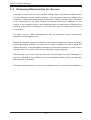
1-1Overview
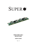
Optimized for enterprise-level heavy-capacity storage applications, Supermicro's
SC837 JBOD chassis features up to twenty-eight (sixteen front plus twelve rear)
3.5" hot-swap HDD bays.
The SC837J design provides high-density storage in a 3U form factor, with high
power efficiency, optimized HDD signal trace routing and improved HDD carrier
design to dampen vibration and maximize performance. Equipped with redundant
1620W (Platinum Level) high-efficiency redundant power supplies with PMBus functionality and I2C for enhanced power management and and five hot-plug redundant
cooling fans, the SC837J is a reliable storage system.
1-2 Shipping List
Please visit the Supermicro Web site for the latest shiping lists and part numbers
for your particular chassis model http://www.supermicro.com/
SC837J Chassis
HDD
Power
Supply
SC837E16-RJBOD1
28x (JBOD) SAS/SATA
1620W redundant
(Gold Level)
SC837E26-RJBOD1
28x (JBOD) SAS/SATA
1620W redundant
(Gold Level)
Model
1-1
SC837J Chassis Manual
1-3 Where to get Replacement Components
Though not frequently, you may need replacement parts for your system. To ensure the highest level of professional service and technical support, we strongly
recommend purchasing exclusively from our Supermicro Authorized Distributors/
System Integrators/Resellers. A list of Supermicro Authorized Distributors/System
Integrators/Resellers can be found at: http://www.supermicro.com. Click the Where
to Buy link.
1-2
SC837J Chassis Manual
1-4 Returning Merchandise for Service
A receipt or copy of your invoice marked with the date of purchase is required before any warranty service will be rendered. You can obtain service by calling your
vendor for a Returned Merchandise Authorization (RMA) number. When returning
to the manufacturer, the RMA number should be prominently displayed on the
outside of the shipping carton, and mailed prepaid or hand-carried. Shipping and
handling charges will be applied for all orders that must be mailed when service
is complete.
For faster service, RMA authorizations may be requested online (http://www.
supermicro.com/support/rma/).
Whenever possible, repack the chassis in the original Supermicro carton, using the
original packaging material. If these are no longer available, be sure to pack the
chassis securely, using packaging material to surround the chassis so that it does
not shift within the carton and become damaged during shipping.
This warranty only covers normal consumer use and does not cover damages incurred in shipping or from failure due to the alteration, misuse, abuse or improper
maintenance of products.
During the warranty period, contact your distributor first for any product problems.
1-3
SC837J Chassis Manual
Notes
1-4
SC837J Chassis Manual
Chapter 2
System Safety
2-1Overview
This chapter provides a quick setup to get your chassis up and running. Following
the steps in the order given should enable you to have your chassis set up and
operational within a minimal amount of time. This quick setup assumes that you are
an experienced technician, familiar with common concepts and terminology.
2-2 Warnings and Precautions
You should inspect the box the chassis was shipped in and note if it was damaged
in any way. If the chassis itself shows damage, file a damage claim with carrier
who delivered your system.
Decide on a suitable location for the rack unit that will hold that chassis. It should
be situated in a clean, dust-free area that is well venilated. Avoid areas where heat,
electrical noise and eletromagnetic fields are generated.
The system must be placed near at two grounded power outlets. When configured,
the SC837J chassis includes one primary and one redundant power supply.
2-3 Preparing for Setup
The SC837J chassis includes a set of rail assemblies which includes mounting
brackets and mounting screws you will need to install the systems into the rack.
Please read this manual in its entirety before you begin the installation procedure.
2-1
SC837J Chassis Manual
2-4 Electrical Safety Precautions
Basic electrical safety precautions should be followed to protect yourself from harm
and the SC837J from damage:
•Be aware of the locations of the power on/off switch on the chassis as well
as the room’s emergency power-off switch, disconnection switch or electrical
outlet. If an electrical accident occurs, you can then quickly remove power from
the system.
•Do not work alone when working with high-voltage components.
•Power should always be disconnected from the system when removing or install-
ing main system components, such as the serverboard and memory modules
(not necessary for hot swappable drives). When disconnecting power, you
should first power-down the system with the operating system and then unplug
the power cords from all the power supply modules in the system.
•When working around exposed electrical circuits, another person who is familiar
with the power-off controls should be nearby to switch off the power if necessary.
•Use only one hand when working with powered-on electrical equipment. This
is to avoid making a complete circuit, which will cause electrical shock. Use
extreme caution when using metal tools, which can easily damage any electrical
components or circuit boards they come into contact with.
•Do not use mats designed to decrease electrostatic discharge as protection from
electrical shock. Instead, use rubber mats that have been specifically designed
as electrical insulators.
•The power supply power cord must include a grounding plug and must be
plugged into a grounded electrical outlet.
•Serverboard battery: CAUTION - There is a danger of explosion if the onboard
battery is installed upside down, which will reverse its polarities This battery
must be replaced only with the same or an equivalent type recommended by
the manufacturer. Dispose of used batteries according to the manufacturer’s
instructions.
2-2
SC837J Chassis Manual
•Handle used batteries carefully. Do not damage the battery in any way; a dam-
aged battery may release hazardous materials into the environment. Do not
discard a used battery in the garbage or a public landfill. Please comply with
the regulations set up by your local hazardous waste management agency to
dispose of your used battery properly.
2-5 General Safety Precautions
•Keep the area around the chassis clean and free of clutter.
•Place the chassis top cover and any system components that have been re-
moved away from the system or on a table so that they won’t accidentally be
stepped on.
•While working on the system, do not wear loose clothing such as neckties and
unbuttoned shirt sleeves, which can come into contact with electrical circuits or
be pulled into a cooling fan.
•Remove any jewelry or metal objects from your body, which are excellent metal
conductors that can create short circuits and harm you if they come into contact
with printed circuit boards or areas where power is present.
•After accessing the inside of the system, close the system back up and secure
it to the rack unit with the retention screws after ensuring that all connections
have been made.
2-6 System Safety
Electrostatic discharge (ESD) is generated by two objects with different electrical
charges coming into contact with each other. An electrical discharge is created to
neutralize this difference, which can damage electronic components and printed
circuit boards. The following measures are generally sufficient to neutralize this
difference before contact is made to protect your equipment from ESD:
•Do not use mats designed to decrease electrostatic discharge as protection from
electrical shock. Instead, use rubber mats that have been specifically designed
as electrical insulators.
•Use a grounded wrist strap designed to prevent static discharge.
•Keep all components and printed circuit boards (PCBs) in their antistatic bags
until ready for use.
2-3
SC837J Chassis Manual
•Touch a grounded metal object before removing any board from its antistatic
bag.
•Do not let components or PCBs come into contact with your clothing, which may
retain a charge even if you are wearing a wrist strap.
•Handle a board by its edges only; do not touch its components, peripheral chips,
memory modules or contacts.
•When handling chips or modules, avoid touching their pins.
•Put the serverboard and peripherals back into their antistatic bags when not
in use.
•For grounding purposes, make sure your computer chassis provides excellent
conductivity between the power supply, the case, the mounting fasteners and
the serverboard.
2-4
SC837J Chassis Manual
Chapter 3
System Interface
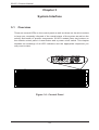
3-1Overview
There are several LEDs on the control panel as well as others on the drive carriers
to keep you constantly informed of the overall status of the system as well as the
activity and health of specific components. SC837J models have two buttons on
the chassis control panel: A reset button and a power on/off switch. This chapter
explains the meanings of all LED indicators and the appropriate responses you
may need to take.
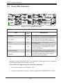
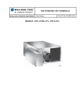
Figure 3-1: Control Panel
3-1
SC837J Chassis Manual
3-2 Control Panel Buttons
There are two push-buttons located on the left handle of the chassis. These are
(in order from top to bottom) a power on/off button and a reset button.
Power: The main power button is used to apply or remove power from the power
supply to the server system. Turning off system power with this button removes
the main power but keeps standby power supplied to the system. Therefore, you
must unplug system before servicing.
Reset: The reset button is used to reboot the system.
3-3 Control Panel LEDs
The control panel located on the left handle of the SC837J chassis has five LEDs.
These LEDs provide you with critical information related to different parts of the
system. This section explains what each LED indicates when illuminated and any
corrective action you may need to take.
!
Power Failure: When this LED flashes, it indicates a failure in the redundant power
supply.
3-2
SC837J Chassis Manual
Overheat/Fan Fail: When this LED flashes, it indicates a fan failure. When continuously on (not flashing) it indicates an overheat condition, which may be caused
by cables obstructing the airflow in the system or the ambient room temperature
being too warm. Check the routing of the cables and make sure all fans are present and operating normally. You should also check to make sure that the chassis
covers are installed. Finally, verify that the heatsinks are installed properly. This
LED will remain flashing or on as long as the overheat condition exists.
1
NIC1: Indicates network activity on GLAN1 when flashing.
2
NIC2: Indicates network activity on GLAN2 when flashing.
HDD: Indicates IDE channel activity. SAS/SATA drive, and/or DVD-ROM drive
activity when flashing.
Power: Indicates power is being supplied to the system's power supply units. This
LED should normally be illuminated when the system is operating.
3-3
SC837J Chassis Manual
3-4 Drive Carrier LEDs
Your chassis uses SAS/SATA.
SAS/SATA Drives
Each SAS/SATA drive carrier has two LEDs.
•Blue:
Solid on = Drive is present and available.
Blinking = Drive is actively being accessed.
Each Serial ATA drive carrier has a blue LED. When illuminated in a solid
on state, this blue LED (on the front of the SAS/SATA drive carrier) indicates
drive activity. A connection to the SAS/SATA backplane enables this LED to
blink on and off when that particular drive is being accessed.
•Red:
Solid on = Drive failure
Blinking = RAID activity
When the red LED is blinking, it indicates that the system is either building,
initializing or rebuilding RAID.
SCSI Drives
This chassis does not support SCSI drives at this time.
3-4
SC837J Chassis Manual
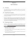
Chapter 4
Chassis Setup and Maintenance
4-1Overview
This chapter covers the steps required to install components and perform maintenance on the chassis. The only tool you will need to install components and perform
maintenance is a Phillips screwdriver. Print this chapter to use as a reference while
setting up your chassis.
!
!
Review the warnings and precautions listed in the manual before
setting up or servicing this chassis. These include information in
Chapter 2: System Safety and the warnings/precautions listed in the
setup instructions.
Safety Warning: Before performing any chassis setup or maintenance, it is recommended that the chassis be removed from the rack
and placed on a stable bench or table. For instructions on how to
uninstall the chassis from the rack, refer to Chapter 5 Rack Installation in this manual.
4-1
SC837J Chassis Manual
4-2 Removing the Chassis Cover
14
2
3
12
13
Figure 4-1: Removing the Chassis Cover
Removing the Chassis Cover
1. Unplug the chassis from any power source.
2. Push down on both release buttons simultaneously.
3. Remove the screws securing the cover to the chassis.
4. Lift the cover up and off the chassis.
!
Warning: Except for short periods of time, do NOT operate the
server without the cover in place. The chassis cover must be in
place to allow proper airflow and prevent overheating.
4-2
SC837J Chassis Manual
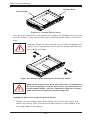
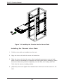
4-3 Installing Removable Hard Drives
2
1
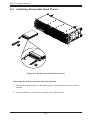
Figure 4-2: Removing a Hard Drive Carrier
Removing Hard Drive Carriers from the Chassis
1. Press the release button on the drive carrier. This extends the drive carrier
handle.
2. Use the handle to pull the drive carrier out of the chassis.
4-3
SC837J Chassis Manual
Dummy Drive
Drive Carrier
Figure 4-3: Chassis Drive Carrier
The drives are mounted in drive carriers to simplify their installation and removal
from the chassis. These carriers also help to promote proper airflow for the drive
bays.
!
Warning: Except for short periods of time (while swapping hard
drives) do not operate the server with the drives removed from
the chassis drive bays.
1
1
Figure 4-4: Removing the Dummy Drive from the Carrier
!
Warning! Enterprise level hard disk drives are recommended
for use in Supermicro chassis and servers. For information on
recommended HDDs, visit the Supermicro Web site at http://
www.supermicro.com/products/nfo/storage.cfm
Installing a Hard Drive to the Hard Drive Carrier
1. Remove the two screws securing the dummy drive to the drive carrier and
remove the dummy drive. Place the hard drive carrier on a flat surface such
as a desk, table or work bench.
4-4
SC837J Chassis Manual
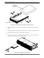
SAS/SATA
Hard Drive
4
4
Drive Carrier
Figure 4-5: Installing the Hard Drive into the Carrier
2. Slide the hard drive into the carrier with the printed circuit board side facing
down.
3. Carefully align the mounting holes in both the drive carrier and the hard drive.
4. Secure the hard drive to the carrier using six screws.
5. Return the drive carrier to the chassis bay. Make sure to close the drive carrier handle to lock the drive carrier into place.
5
Figure 4-6: Installing the Hard Drive
4-5
SC837J Chassis Manual
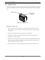
4-6 System Fans
Seven hot-swappable, heavy-duty fans provide cooling for the chassis. These fans
circulate air through the chassis, thereby lowering the chassis internal temperature.
Release Tab
Air Direction
Indicator
Figure 4-7: System Fan
Replacing a System Fan
1. Open the chassis while the system is running to determine which fan has
failed. (Never run the server for an extended period of time with the chassis
cover open.)
2. Remove the failed fan's power cord from the serverboard.
3. Press the fan release tab to lift the failed fan from the chassis and pull it
completely out of the chassis.
4. Place the new fan into the vacant space in the housing while making sure the
arrows on the top of the fan (indicating air direction) point in the same direction as the arrows on the other fans.
5. Check that the fan is working properly before replacing the chassis cover.
4-6
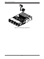
SC837J Chassis Manual
Figure 4-8: Placing the System Fan
4-7
SC837J Chassis Manual
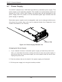
4-7 Power Supply
The SC837J chassis has a 1620 Watt high-efficiency redundant power supply. This
power supply is auto-switching capable. This enables it to automatically sense and
operate at a 100v to 240v input voltage. An amber light will be illuminated on the
power supply when the power is off. An illuminated green light indicates that the
power supply is operating.
Redundant power supplies are hot-swappable, and can be changed without powering down the system. New units can be ordered directly from Supermicro (see
contact information in the Preface).
Release Tab
Figure 4-9: Power Supply Release Tab
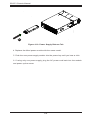
Changing the Power Supply:
1. If your chassis includes a redundant power supply (at least two power modules), you can leave the server running and remove only one power supply. If
your server has only one power supply, you must power down the server and
unplug the power cord.
2. Push the release tab (on the back of the power supply) as illustrated.
3. Pull the power supply out using the handle provided.
4-8
SC837J Chassis Manual
15
Figure 4-10: Power Supply Release Tab
4. Replace the failed power module with the same model.
5. Push the new power supply module into the power bay until you hear a click.
6. If using only one power supply, plug the AC power cord back into the module
and power up the server.
4-9
SC837J Chassis Manual
Notes
4-10
SC837J Chassis Manual
Chapter 5
Rack Installation
5-1Overview
This chapter provides a quick setup for installing the chassis into a rack. Following
these steps in the order given should enable you to have the system installed within
a minimum amount of time.
5-2 Unpacking the System
You should inspect the box the chassis was shipped in and note if it was damaged
in any way. If the chassis itself shows damage you should file a damage claim with
the carrier who delivered it.
Decide on a suitable location for the rack unit that will hold your chassis. It should
be situated in a clean, dust-free area that is well ventilated. Avoid areas where heat,
electrical noise and electromagnetic fields are generated. You will also need to position the rack near a grounded power outlet. Be sure to read the Rack Precautions
and General Server Precautions in the next section.
5-3 Preparing for Setup
The box your chassis was shipped in includes a set of rail assemblies (two inner
rails and two outer rails). and the mounting screws you will need to install the system
into the rack. Please read this section in its entirety before you begin the installation
procedure outlined in the sections that follow.
Choosing a Setup Location
•Leave enough clearance in front of the rack to enable you to open the front
door completely (~25 inches).
•Leave approximately 30 inches of clearance in the back of the rack to allow for
sufficient airflow and ease in servicing.
5-1
SC837J Chassis Manual
!
Warnings and Precautions!
!
•This product is for installation only in a Restricted Access Location (dedicated
equipment rooms, service closets and the like).
Rack Precautions
•Ensure that the leveling jacks on the bottom of the rack are fully extended to
the floor with the full weight of the rack resting on them.
•In single rack installation, stabilizers should be attached to the rack.
•In multiple rack installations, the racks should be coupled together.
•Always make sure the rack is stable before extending a component from the
rack.
•You should extend only one component at a time - extending two or more simultaneously may cause the rack to become unstable.
General Server Precautions
•Review the electrical and general safety precautions that came with the components you are adding to your chassis.
•Determine the placement of each component in the rack before you install the
rails.
•Install the heaviest server components on the bottom of the rack first, and then
work up.
•Use a regulating uninterruptible power supply (UPS) to protect the server from
power surges, voltage spikes and to keep your system operating in case of a
power failure.
•Allow the hot-plug hard drives and power supply modules to cool before touching them.
5-2
SC837J Chassis Manual
Rack Mounting Considerations
Ambient Operating Temperature
If installed in a closed or multi-unit rack assembly, the ambient operating temperature of the rack environment may be greater than the ambient temperature
of the room. Therefore, consideration should be given to installing the equipment
in an environment compatible with the manufacturer’s maximum rated ambient
temperature.
Reduced Airflow
Equipment should be mounted into a rack so that the amount of airflow required
for safe operation is not compromised.
Mechanical Loading
Equipment should be mounted into a rack so that a hazardous condition does not
arise due to uneven mechanical loading.
Circuit Overloading
Consideration should be given to the connection of the equipment to the power
supply circuitry and the effect that any possible overloading of circuits might have
on overcurrent protection and power supply wiring. Appropriate consideration of
equipment nameplate ratings should be used when addressing this concern.
Reliable Ground
A reliable ground must be maintained at all times. To ensure this, the rack itself
should be grounded. Particular attention should be given to power supply connections other than the direct connections to the branch circuit (for example, the use
of power strips, etc.).
5-3
SC837J Chassis Manual
5-4 Rack Mounting Instructions
This section provides information on installing the SC837J chassis into a rack
unit with the rails provided. There are a variety of rack units on the market, which
may mean the assembly procedure may differ slightly. You should also refer to the
installation instructions that came with the rack unit you are using.
13
Screws
1
12
Figure 7-2: Installing the Inner Rails
Installing the Inner Rails
Inner Rail Installation
1. Place the inner rail on the side of the chassis aligning the hooks of the chassis with the holes in the inner rail.
2. Slide the inner rail toward the front of the chassis.
3. Secure the chassis with four screws as illustrated.
4. Repeat steps 1-3 for the other inner rail.
5-4
SC837J Chassis Manual
B
1
D
1
1A
C
1
Figure 7-3: Installing the Outer Rails
Installing the Outer Rails on the Rack
Outer rails attach to the server rack and hold the chassis in place. The outer rails
for the SC837J chassis extend between thirty inches and thirty-three inches.
Installing the Outer Rails
1. Begin by measuring the distance from the front to the back of the rack.
2. Slide the shorter outer rail (A) into the longer outer rail (B).
3. Attach the front of the shorter outer rail (A) to the front of the rack and the
back of the longer outer rail (B) to the rear of the rack.
4. Adjust both the shorter and longer outer rails to the proper distance so that
they fit snugly into the rack and secure with the screws provided.
5. Press the release tab (C) on the inside of the outer rail to release the outer
rail extension (D)
6. Repeat steps 1 through 5 for the remaining outer rail.
5-5
SC837J Chassis Manual
13
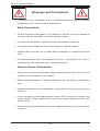
Figure 7-4: Installing the Chassis into the Server Rack
Installing the Chassis into a Rack
1. Confirm outer rails are installed on the rack.
2. Align the inner rails with the outer rail extension.
3. Slide the inner rails into the outer rails, keeping the pressure even on both
sides (it may be necessary to depress the locking tabs when inserting). When
the server has been pushed completely into the rack, the locking tabs will
"click into the secure, locked position.
4. (Optional) Insert and tighten the thumbscrews which secure the server to the
rack.
5-6
SC837J Chassis Manual
Appendix A
SC837J Cables and Hardware
A-1Overview
This appendix lists supported cables for your chassis system. It only includes the
most commonly used components and configurations. For more compatible cables,
refer to the manufacturer of the motherboard you are using and our Web site at:
www.supermicro.com.
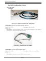
A-2 Cables Included with SC837J Chassis (SAS/SATA)
SC837J
Part #
Type
Length
Description
CBL-0102L
Cable
51 cm
CBL-0386L
Cable
---
CBL-0108L-02
Cable
39 cm
iPass to iPass PBF.
CBL-0421L
Cable
55 cm
iPass to iPass PBF.
I2C cable for the SATA LED
4-port (two in and two out) external
to internal iPass connector.
A-1
SC837J Chassis Manual
A-3 Compatible Cables
These cables are compatible with the SC837J chassis.
Alternate SAS/SATA cables
Some compatible motherboards have different connectors. These cables must be
purchased separately.
Cable Name: SAS Cable
Quantity: 4
Part #: CBL-0175L
Alt. Name: "Big Four"
Description: This cable has one SFF-8484 (32-pin) connector on one end and four
SAS connectors (seven pins each) at the other. This cable connects from the host
(motherboard or other controller) to the backplane SAS hard drive port.
Cable Name: SAS Cable
Quantity: 4
Part #: CBL-0116
Alt. Name: iPass or "Small Four"
Description: This cable has one iPass (SFF-8087/Mini-SAS) connector (36-pin) at
one end and four SAS connectors on one end. This cable connects from the host
(motherboard or other controller) to the backplane SAS hard drive port.
A-2
SC837J Chassis Manual
Extending Power Cables
Although Supermicro chassis are designed with to be efficient and cost-effective,
some compatible motherboards have power connectors located in different areas.
To use these motherboards you may have to extend the power cables to the mother
boards. To do this, use the following chart as a guide.
Power Cable Extenders
Number of Pins
Cable Part #
Length
24-pin
CBL-0042
7.9” (20 cm)
20-pin
CBL-0059
7.9” (20 cm)
8-pin
CBL-0062
7.9” (20 cm)
4-pin
CBL-0060
7.9” (20 cm)
Front Panel to the Motherboard
The SC837J chassis includes a cable to connect the chassis front panel to the
motherboard. If your motherboard uses a different connector, use the following list
to find a compatible cable.
Front Panel to Motherboard Cable (Ribbon Cable)
Number of Pins
(Front Panel)
Number of Pins
(Motherboard)
Cable Part #
16-pin
16-pin
CBL-0049
16-pin
20-pin
CBL-0048
20-pin
20-pin
CBL-0047
16-pin
various*
CBL-0068
20-pin
various*
CBL-0067
* Split cables: Use these cable if your motherboard requires several different connections from the front panel.
A-3
SC837J Chassis Manual
A-4 Chassis Screws
The accessory box includes all the screws needed to set up your chassis. This
section lists and describes the most common screws used. Your chassis may not
require all the parts listed.
M/B
HARD DRIVE
Flat head
6-32 x 5 mm
[0.197]
Pan head
6-32 x 5 mm
[0.197]
DVD-ROM, CD-ROM, and FLOPPY DRIVE
Pan head
6-32 x 5 mm
[0.197]
Flat head
6-32 x 5 mm
[0.197]
Round head
M3 x 5 mm
[0.197]
Round head
M2.6 x 5 mm
[0.197]
RAIL
Flat head
M4 x 4 mm
[0.157]
Round head
M4 x 4 mm
[0.157]
Flat head
M5 x 12 mm[0.472]
Washer for M5
M/B STANDOFFS
M/B standoff
6-32 to 6-32
M/B (CPU)
standoff
M5 to 6-32
Thumb screw
6-32 x 5 mm
[0.197]
A-4
1/U M/B standoff
6-32 x 5 mm
[0.197]
SC837J Chassis Manual
Appendix B
SC837J Power Supply Specifications
This appendix lists power supply specifications for your chassis system.
SC837J
1620W
MFR Part #
PWS-1K62P-1R
AC Input
1000W: 100-120 V, 50-60 Hz, 12-10 Amp
1200W: 120-140 V, 50-60 Hz, 12-10 Amp
1620W: 180-240 V, 50-60 Hz, 10.5-8 Amp
DC Output
4 Amp
+5V Standby
1000W: 84 Amp
DC Output 1200W: 100 Amp
+12V 1620W: 135 Amp
B-1
SC837J Chassis Manual
Notes
B-2
SC837J Chassis Manual
Appendix C
SAS2-837EL Backplane Specifications
To avoid personal injury and property damage, carefully follow all the safety steps
listed below when accessing your system or handling the components.
C-1 ESD Safety Guidelines
Electrostatic Discharge (ESD) can damage electronic components. To prevent damage to your system, it is important to handle it very carefully. The following measures
are generally sufficient to protect your equipment from ESD.
Use a grounded wrist strap designed to prevent static discharge.
•
•Touch a grounded metal object before removing a component from the antistatic
bag.
•Handle the backplane by its edges only; do not touch its components, peripheral
chips, memory modules or gold contacts.
•When handling chips or modules, avoid touching their pins.
•Put the backplane and peripherals back into their antistatic bags when not in
use.
C-2 General Safety Guidelines
•Always disconnect power cables before installing or removing any components
from the computer, including the backplane.
•Disconnect the power cable before installing or removing any cables from the
backplane.
•Make sure that the backplane is securely and properly installed on the motherboard to prevent damage to the system due to power shortage.
C-1
SC837J Chassis Manual
C-3 An Important Note to Users
All images and layouts shown in this user's guide are based upon the latest PCB
revision available at the time of publishing. The card you have received may or may
not look exactly the same as the graphics shown in this manual.
C-4 Introduction to the SAS2-837EL Backplane
The SAS2-837EL backplane has been designed to utilize the most up-to-date technology available, providing your system with reliable, high-quality performance.
This manual reflects SAS2-837EL1 and SAS2-837EL2 Revision 1.00, the most
current release available at the time of publication. Always refer to the Supermicro
Web site at www.supermicro.com for the latest updates, compatible parts and supported configurations.
The SAS2-837EL1 backplane includes a primary expander chip and primary SAS
connectors. The SAS2-837EL2 includes of both primary and secondary expander
chips, as well as primary and secondary SAS connectors. The primary and secondary expanders are redundant, so that if one should fail, the other will take over.
C-2
SC837J Chassis Manual
C-5 Front Connectors
EC4
8
DESIGNED IN USA
1
1
BAR CODE
U332
GND
SEC_FLASH
GND
U5
+
+5V
U312
+
B18
16
1
+
+
1
PWR1
+12V
+5V
B1
EC1
1
Q2
1
GND
+
+
EC2
SEC_J4
C2971
GND
17
J25
+
C2970
PWR2
FANFAIL_LED_DISABLE
15
1
EC19
C
UART_S
4
C
SEC_J0
C871
4
A
+
1
1
A
C867
4
B1
EXPDBG2
4
A
ACT25
MH7
MH5
SEC_J3
+
UART_P
EXPDBG1
+12V
EC3
FAN_MONITOR_DISABLE
A1
FANFAIL1
OVERHEATFAIL1
+
UNLESS OTHERWISE
SPECIFIED DIMENSIONS
ARE IN INCHES
TOLERANCES
DECIMAL
ANGLE
X .1
30
XX .03
MACH FINISH
XXX.010
+
+
C2973
+
L148
15
REV: 1.00
BPN-SAS2-837EL2
L147
Layout Team 1
H/W:Shen Ping
8-10-2010
C430
SILKSCREEN
PRIMARY-SIDE
DESINGER:
A18
C
33
WWN
U17
L149
B1
+
12
RR
DESIGNED BY SUPERMICRO U.S.A.
www.supermicro.com
DATE:
B1
MH13
17
1
5
FAN3
4
1
RA611
MH10
Y
MH4
MH1
Q1
U1
C2972
+5V
+
+
GND
L151
28
15
GND
K
MH11
SAN JOSE,CA 95131
PROJECT NAME:
TEL:408-503-8000 FAX:408-503-8008
14
1
+
+
25
+12V
SEC_J2
A1
B18
+
U4
PWR3
C868
10
SUPER
Q3
B18
+
EC18
EC13
EC17
A1
11
1
EC8
A18
L398
MH8
EC36
EC20
20
C377
13
1
+
15
MH2
28
+5V
FAN1
L153
+
14
C870
25
+
GND
EC35
10
B18
+
GND
+
+
PRI_J1
B1
+
L1
A18
+
+12V
C864
A1
EC9
20
PWR4
EC10
+
B18
Y10
B18
+
5
U6
18
+
PRI_J2
B1
12
1
BCA420
E
A18
EC16
BC91
EC15
+
C863
K
R
Y
AE
B18
REV: 1.00
AH
A1
+
BC92
PRI_I2C1
PRI_J3
B1
17
MH3
ACTLED1
+
BPN-SAS2-837EL2
EC27
+
C
PRI_I2C
+
16
B18
1
C
5V_LED
A
EC25
19
C2988
12V_LED
A
1
1
PRI_J0
B1
PRI_FLASH
MH6
C865
L152
C861
C866
+
EC22
13
WWN
EC26
BCA534
C862
MH9
C
B18
ACT24
A
PRI_J4
B1
+
10
1
J24
+
U16
BC52
+
+
+
16
1
EC28
MH12
12
12
FAN2
15
12
15
Figure C-1: Front Connectors
Front Connectors
1. Dual primary I2C connectors:
PRI_I2C and PRI_I2C1
2. Power connectors:
PWR1, PWR2, PWR3 and PWR4
11. Secondary SAS port: SEC_J0
(Not present on the SAS2-837EL1
backplane)
3. Primary expander chip
12.Secondary SAS port SEC_J1
(Not present on the SAS2-837EL1
backplane)
4. Secondary expander chip
(Not present on the SAS2-837EL1
backplane)
13.Secondary SAS port SEC_J2
(Not present on the SAS2-837EL1
backplane)
5. Fan connectors: FAN1, FAN2 and
FAN3
14.Secondary SAS port SEC_J3
(Not present on the SAS2-837EL1
backplane)
6. Primary SAS port: PRI_J0
15.Secondary SAS port SEC_J4
(Not present on the SAS2-837EL1
backplane)
7. Primary SAS port: PRI_J1
8. Primary SAS port: PRI_J2
16.Primary Ethernet port: J24
9. Primary SAS port: PRI_J3
17.Secondary Ethernet port: J25
(Not present on the SAS2-837EL1
backplane)
10.Primary SAS port PRI_J4
C-3
SC837J Chassis Manual
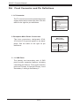
C-6 Front Connector and Pin Definitions
1. Primary I2C Connector
The I2C connector is used to monitor the power
supply status and to control the fans. See the
table on the right for pin definitions.
I2C Connector
Pin Definitions
Pin#
Definition
1
Data
2
Ground
3
Clock
4
No Connection
2. Backplane Main Power Connectors
The 4-pin connectors, designated PWR1,
PWR2 and PWR3 provide power to the
backplane. See the table on the right for
pin definitions.
Backplane
Main Power
4-Pin Connector
Pin#
1
2 and 3
4
Definition
+12V
Ground
+5V
3. and 4. Primary and Secondary Expander
Chips
The primary and secondary expander chips
allow the SAS2-837EL2 backplane to support dual ports, cascading, and failover.
SAS2-837EL1 supports cascading.
5. Fan Connectors
Fan Connectors
The 4-pin connectors, designated FAN1,
through FAN3, provide power to the fans.
See the table on the right for pin definitions.
C-4
Pin#
Definition
1
Ground
2
+12V
3
Tachometer
4
Empty
SC837J Chassis Manual
6. - 15. SAS Ports
The primary and secondary sets of SAS
ports provide expander features including cascading and failover. The primary
SAS ports are located on the left side of
the board, and are designated Primary 0
through Primary 4. The secondary SAS
ports are on the right side of the board
and are designated Secondary 0 through
Secondary 4. Note that secondary SAS
ports are not present on the SAS2-837EL1
backplane.
16. - 17. Primary and Secondary Ethernet
Ports
The primary and secondary Ethernet
ports are designated J24 (primary) and
J25 (secondary).The secondary Ethernet
ports are not present on the SAS2-837EL1
backplane.
C-5
SC837J Chassis Manual
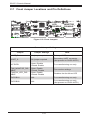
C-7 Front Jumper Locations and Pin Definitions
MH13
+
+
EC4
EC35
C
U1
EC36
A
ACT25
EC20
+
+
+
+
+
+
A1
17
16
Q3
15
B18
L153
A1
10
+
PRI_J0
B1
PRI_FLASH
L152
+
5
B18
BCA534
EC22
+
BCA420
C864
C
PRI_J4
B1
FANFAIL_ FAN_
LED_
MONITOR_
DISABLE DISABLE
EC10
+
E
K
R
Y
AE
AH
ACT24
A
C863
+
+
+
C865
MH8
C862
MH6
C861
C866
J24
BC52
L151
WWN
EC26
+
U16
+
MH9
+
+
EC28
MH12
33
WWN
U17
1
20
C2988
B18
SEC_J2
B1
8
28
MH3
+
MH2
U6
1
U332
+
SEC_FLASH
PWR1
+12V
+5V
GND
GND
U5
+5V
U312
B18
+
GND
DESIGNED IN USA
+
BAR CODE
1
+
C
+
MH7
B1
EC1
FAN3
4
1
RA611
MH10
MH4
L148
L147
FAN2
Q2
UNLESS OTHERWISE
SPECIFIED DIMENSIONS
ARE IN INCHES
Layout Team 1
H/W:Shen Ping
8-10-2010
C430
SILKSCREEN
PRIMARY-SIDE
DESINGER:
C
+
RR
DESIGNED BY SUPERMICRO U.S.A.
www.supermicro.com
DATE:
SAN JOSE,CA 95131
PROJECT NAME:
TEL:408-503-8000 FAX:408-503-8008
Q1
EC2
Y
MH1
SUPER
GND
1
MH11
A
+12V
+
+
5
K
EC17
UART_S
4
EC19
A
+5V
10
FAN1
4
B1
PWR2
C2971
GND
B1
EXPDBG2
4
SEC_J4
+
15
GND
4
J25
C2970
+12V
EC13
1
B18
+
20
PWR3
C868
+5V
EXPDBG1
SEC_J0
25
EC18
U4
GND
+
GND
1
C871
L1
L398
28
+
+
+12V
A18
PWR4
+
EC15
B18
UART_P
+
B18
A1
C867
Y10
ACTLED1
+
PRI_J2
B1
1
A18
BC91
MH5
SEC_J3
C377
EC16
BC92
A1
FANFAIL_LED_DISABLE
A18
EC8
UART_P
EXPDBG2
EXPDBG1 UART_S
C870
+
+
B18
FANFAIL1
OVERHEATFAIL1
PRI_J1
B1
+
REV: 1.00
+
ACTLED1
+
BPN-SAS2-837EL2
C2973
1
C
FAN_MONITOR_DISABLE
B18
C
5V_LED
A
C2972
PRI_I2C1
PRI_J3
B1
12V_LED
A
EC3
L149
A18
1
A1
EC25
EC9
25
+
EC27
PRI_I2C
REV: 1.00
BPN-SAS2-837EL2
TOLERANCES
DECIMAL
ANGLE
X .1
30
XX .03
MACH FINISH
XXX.010
Figure C-2: Front Jumpers
General Jumper Settings
Jumper
Jumper Settings
Note
UART_P
No jumper required
Primary UART connector
UART_S
No jumper required
Secondary UART connector
(Not present on SAS2-847E1)
ACTLED1
Open: Disable
Closed: Enable
For manufacturing use only
FAN_MONITOR_DISABLE
Open: Enable
Closed: Disable
Fan monitor settings
FANFAIL_LED_DISABLE
Open: Enable
Closed: Disable
Disables the fan failure LED
EXPDBG1
N/A
For manufacturing use only.
EXPDBG2
N/A
For manufacturing use only
(Not present on SAS2-847E1)
C-6
SC837J Chassis Manual
Explanation of Jumpers
To modify the operation of the backplane,
jumpers can be used to choose between
optional settings. Jumpers create shorts
between two pins to change the function
of the connector. Pin 1 is identified with
a square solder pad on the printed circuit
board. Note: On two pin jumpers, "Closed"
means the jumper is on and "Open" means
the jumper is off the pins.
C-7
Connector
Pins
3
2
1
3
2
1
Jumper
Setting
SC837J Chassis Manual
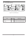
C-8 Front LED Indicators
EC4
16
1
8
1
1
DESIGNED IN USA
SEC_FLASH
GND
U5
+
GND
BAR CODE
+
+
1
+5V
U312
B18
+
FANFAIL_LED_DISABLE
PWR1
+12V
+5V
+
L148
L147
Q1
FAN_MONITOR_DISABLE
+
GND
C
SEC_J4
C2971
GND
U332
B1
EC1
FAN3
RA611
4
1
MH10
MH4
FAN2
Q2
UNLESS OTHERWISE
SPECIFIED DIMENSIONS
ARE IN INCHES
Layout Team 1
H/W:Shen Ping
8-10-2010
C430
DESINGER:
FANFAIL1
+
C2970
+
+
SILKSCREEN
PRIMARY-SIDE
RR
DESIGNED BY SUPERMICRO U.S.A.
www.supermicro.com
DATE:
UART_S
4
EC2
Y
MH1
SAN JOSE,CA 95131
PROJECT NAME:
TEL:408-503-8000 FAX:408-503-8008
4
B1
PWR2
+12V
MH7
C
SEC_J0
C871
1
EC19
1
MH11
J25
5
K
EC17
B1
EXPDBG2
4
A
+
EXPDBG1
B18
4
A
B18
1
1
SEC_J3
C867
+5V
10
FAN1
FANFAIL1
OVERHEATFAIL1
+
+
GND
EC3
MH5
+
15
GND
A1
A1
UART_P
+
U4
A18
+
+12V
17
B1
EC8
+
20
PWR3
+
A18
+
C2973
+
+
25
EC18
C868
SEC_J2
C2972
Y10
+
L1
+5V
A
ACT25
+
+
C377
C870
28
B18
U1
28
ACTLED1
B18
C
33
WWN
U17
L149
L398
PRI_J2
B1
EC13
SUPER
+
25
1
PRI_J1
ACT25
EC9
A18
PWR4
GND
+
+
20
U6
B1
BC91
GND
A1
OVERHEATFAIL1
EC16
BC92
+12V
+
15
+
A18
L152
EC35
Q3
MH2
B18
REV: 1.00
5V_LED
EC15
+
10
+
MH3
MH13
EC20
+
B18
C2988
+
BPN-SAS2-837EL2
EC36
5
PRI_J0
PRI_I2C1
PRI_J3
B1
C
L153
A1
B18
EC27
PRI_I2C
C
5V_LED
A
+
E
B1
PRI_FLASH
A1
12V_LED
A
BCA420
+
C863
K
R
Y
AE
AH
+
12V_LED
EC25
EC10
+
C864
B18
BCA534
EC22
+
+
C865
MH8
C862
MH6
C861
C866
L151
WWN
EC26
C
PRI_J4
B1
ACT24
A
ACT24
J24
+
U16
BC52
+
MH9
+
+
EC28
MH12
REV: 1.00
BPN-SAS2-837EL2
TOLERANCES
DECIMAL
ANGLE
X .1
30
XX .03
MACH FINISH
XXX.010
Figure C-3: Front LED Indicators
Front LEDs
LED
Default
State
Specification
5V_LED1
On
Blue LED indicates backplane power activity. Light is on during normal operation
12V_LED2
On
Blue LED indicates backplane power activity. Light is on during normal operation.
ACT24
On
Indicates activity in the primary section of
the backplane.
ACT25
On
Indicates activity in the secondary section
of the backplane. (Not present on SAS2837EL1 backplane)
OVERHEATFAIL1
Off
Red LED indicates an overheated condition. Light is off during normal operation
FANFAIL1
Off
Red LED indicates a fan failure. Light is
off during normal operation
Activation of the OVERHEATFAIL1 and FANFAIL1 LEDs indicate that a condition
requiring immediate attention has occurred.
These LEDs are triggered by the following conditions:
1. A fan failure triggers the FANFAIL1 LED.
2. A system temperature over 45º Celsius triggers the OVERHEATFAIL1 LED.
C-8
SC837J Chassis Manual
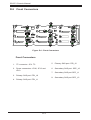
C-9 Rear Connectors and LED Indicators
C
C
C
C
U326
C
C
C
ACT20
ACT#14
C
FAIL#15
A FAIL21
C
A
CA
A
FAIL#14
A
FAIL20
A
A
ACT21
FAIL14
FAIL#10
ACT19
ACT#13
C
ACT13
C
ACT#9
ACT18 C
ACT#12
C
ACT12
C
FAIL#12
A FAIL18
A
A
J18
A
FAIL12
FAIL6
FAIL#8
C
A
A
C
SAS #12
J12
SAS
#8
FAIL#13
J19
SAS
#13
ACT#8
ACT6
A
SAS #8
A FAIL19
SAS #13
J13
SAS
#9
ACT#4 FAIL#4
C
FAIL0
FAIL#0
J6
SAS
#4
C
A
FAIL13
C
A
A
FAIL7
FAIL#5
SAS #9
FAIL#9
C
A
C
REV: 1.00
BPN-SAS2-837EL2
J20
SAS
#14
A
J7
#5
ACT0 C
Layout Team 1
H/W:Shen Ping
SAS
#15
J14
ACT7 C
BC31
SAS
ACT#0
SAS #4
UNLESS OTHERWISE
SPECIFIED DIMENSIONS
ARE IN INCHES
8-10-2010
#10
ACT#5
A
DESINGER:
DESIGNED BY SUPERMICRO U.S.A.
www.supermicro.com
DATE:
SAN JOSE,CA 95131
PROJECT NAME:
TEL:408-503-8000 FAX:408-503-8008
SAS #14
SAS
A
FAIL#1
SUPER
J0
SAS
#0
NRREERCSKLIS
EDIS-YRADNOCES
A
C
FAIL8
ACT1 A FAIL1
C
SAS #0
J21
32
17
ACT14
A
C
SAS #10
ACT#1
SAS #5
J1
SAS
#1
33
16
ACT#10
ACT8
J8
SAS
C
SAS #1
48
J15
SAS
#11
ACT#6 FAIL#6
FAIL2
FAIL#2
#6
SAS #6
SAS #15
A
SAS #11
FAIL#7
ACT2
J2
SAS
#2
J9
SAS
#7
ACT#2
SAS #2
FAIL15
A
A
SAS #7
A
A FAIL9
C
FAIL3
A
C
FAIL#3
#3
ACT#15
ACT3
J3
SAS
ACT#11
C
ACT9
ACT#7
C
ACT#3
SAS #3
SAS
#12
Figure C-4: Rear Connectors
TOLERANCES
DECIMAL
ANGLE
X .1
30
XX .03
MACH FINISH
XXX.010
Rear SAS/SATA Connectors
Rear
Connector
SAS Drive
Number
Rear
Connector
SAS Drive
Number
SAS #0
SAS/SATA HDD #0
SAS #8
SAS/SATA HDD #8
SAS #1
SAS/SATA HDD #1
SAS #9
SAS/SATA HDD #9
SAS #2
SAS/SATA HDD #2
SAS #10
SAS/SATA HDD #10
SAS #3
SAS/SATA HDD #3
SAS #11
SAS/SATA HDD #11
SAS #4
SAS/SATA HDD #4
SAS #12
SAS/SATA HDD #12
SAS #5
SAS/SATA HDD #5
SAS #13
SAS/SATA HDD #13
SAS #6
SAS/SATA HDD #6
SAS #14
SAS/SATA HDD #14
SAS #7
SAS/SATA HDD #7
SAS #15
SAS/SATA HDD #15
Rear LED Indicators
Rear
Connector
Hard Drive
Activity LED
Failure
LED
Rear
Connector
Hard Drive Activity LED
Failure
LED
SAS #0
ACT #0
FAIL #0
SAS #8
ACT #8
FAIL #8
SAS #1
ACT #1
FAIL #1
SAS #9
ACT #9
FAIL #9
SAS #2
ACT #2
FAIL #2
SAS #10
ACT #10
FAIL #10
SAS #3
ACT #3
FAIL #3
SAS #11
ACT #11
FAIL #11
SAS #4
ACT #4
FAIL #4
SAS #12
ACT #12
FAIL #12
SAS #5
ACT #5
FAIL #5
SAS #13
ACT #13
FAIL #13
SAS #6
ACT #6
FAIL #6
SAS #14
ACT #14
FAIL #14
SAS #7
ACT #7
FAIL #7
SAS #15
ACT #15
FAIL #15
C-9
SC837J Chassis Manual
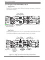
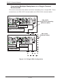
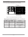
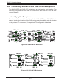
C-10Single and Dual Port Expanders
Single Ports
SAS2-837EL1 backplanes have a single-port expander that access all hard drives
and supports cascading.
From HBA or
higher backplane
MH6
C861
MH8
EC35
E
K
R
Y
C
L153
EC36
+
+
17
33
+
+
+
+
WWN
A1
16
Q3
15
B18
A
ACT25
EC20
A1
10
PRI_J0
U1
C864
5
B1
PRI_FLASH
MH13
EC4
+
+
+
EC10
+
+
BCA420
C863
+
+
C865
L152
L151
WWN
C866
+
EC22
J0
AE
BCA534
AH
C
B18
+
ACT24
A
PRI_J4
B1
C862
EC26
J24
BC52
+
U16
+
MH9
+
+
EC28
MH12
U17
1
20
C2988
B18
B1
SEC_J2
8
EC9
25
+
EC27
PRI_I2C
28
MH3
A1
+
MH2
MH7
U6
+
1
1
DESIGNED IN USA
GND
+5V
U312
FAN3
EC1
RA611
4
MH10
1
FAN2
Primary ports
Expander 1
TOLERANCES
DECIMAL
ANGLE
X .1
30
XX .03
MACH FINISH
XXX.010
REV: 1.00
BPN-SAS2-837EL2
GND
B1
Y
Q2
UNLESS OTHERWISE
SPECIFIED DIMENSIONS
ARE IN INCHES
Layout Team 1
H/W:Shen Ping
8-10-2010
SEC_FLASH
B18
+
+
L148
L147
C430
DESINGER:
DESIGNED BY SUPERMICRO U.S.A.
www.supermicro.com
DATE:
U5
PWR1
+12V
+5V
MH4
To lower backplane in
cascaded system
SAN JOSE,CA 95131
PROJECT NAME:
TEL:408-503-8000 FAX:408-503-8008
BAR CODE
GND
+
GND
5
+
SILKSCREEN
PRIMARY-SIDE
RR
Q1
U332
+
B1
PWR2
+12V
10
MH1
SUPER
+
+
15
1
MH11
EC17
C
20
+5V
K
FAN1
C
B18
+
A
GND
UART_S
4
A
GND
4
EC2
SEC_J4
J1
+12V
EC13
C2971
PWR3
C868
1
1
SEC_J0
C871
25
EC18
EXPDBG1
EC19
C2970
L1
+5V
U4
GND
+
GND
+
+
+12V
A18
PWR4
+
EC15
B1
EXPDBG2
4
+
+
28
B18
4
1
C867
Y10
PRI_J2
B1
B18
1
L398
BC91
MH5
A1
UART_P
+
BC92
A1
+
A18
FANFAIL_LED_DISABLE
A18
EC8
C377
C870
SEC_J3
B18
EC16
FANFAIL1
OVERHEATFAIL1
PRI_J1
+
B1
+
+
REV: 1.00
+
ACTLED1
C2973
1
BPN-SAS2-837EL2
C
FAN_MONITOR_DISABLE
B18
C
5V_LED
A
C2972
PRI_J3
B1
12V_LED
A
EC25
J25
EC3
L149
A18
PRI_I2C1
Dual Ports
SAS2-837EL2 backplanes have dual-port expanders that access all the hard drives.
These dual-port expanders support cascading, failover, and multipath.
From HBA or
higher backplane
L151
MH13
+
EC4
+
+
+
BCA420
+
EC10
+
EC35
J1
E
C
C864
L153
U1
5
EC36
A
ACT25
EC20
+
+
10
A1
17
+
+
15
+
A1
16
Q3
+
B18
MH8
C862
+
C863
K
PRI_J0
R
B1
PRI_FLASH
C865
Y
+
EC22
MH6
C861
AE
BCA534
AH
C
B18
+
ACT24
A
PRI_J4
B1
C866
J0
J24
BC52
L152
WWN
EC26
+
U16
+
MH9
+
+
EC28
MH12
From HBA or
higher backplane
33
WWN
U17
1
20
C2988
B18
SEC_J2
B1
8
28
MH3
A1
U6
+
REV: 1.00
BPN-SAS2-837EL2
Q1
To lower
backplane
in cascaded
system
TOLERANCES
DECIMAL
ANGLE
X .1
30
XX .03
MACH FINISH
XXX.010
1
1
PWR1
+12V
+5V
B18
GND
GND
U5
+5V
B1
EC1
1
FAN3
1
Y
MH4
FAN2
Q2
To lower
backplane
in cascaded
system
Secondary
ports
Expander 2
Figure C-5: Single and Dual Port Cascading Configurations
C-10
DESIGNED IN USA
UNLESS OTHERWISE
SPECIFIED DIMENSIONS
ARE IN INCHES
Layout Team 1
H/W:Shen Ping
8-10-2010
L148
SILKSCREEN
PRIMARY-SIDE
DESINGER:
DESIGNED BY SUPERMICRO U.S.A.
www.supermicro.com
DATE:
L147
RR
ports
Expander 1
SAN JOSE,CA 95131
PROJECT NAME:
TEL:408-503-8000 FAX:408-503-8008
C430
SPrimary
UPER
EC17
GND
U312
MH1
FAN1
GND
SEC_FLASH
MH11
J0
BAR CODE
+
K
U332
+
+
5
EC2
+
B1
PWR2
+12V
+
10
1
+
15
1
+
20
+5V
EC19
+
GND
UART_S
4
+
J1
GND
B1
EXPDBG2
4
SEC_J4
+12V
EC13
C2971
PWR3
C868
MH5
4
4
C
EC18
B18
C2970
L1
+5V
SEC_J0
GND
25
U4
GND
+
+12V
+
+
PWR4
A18
+
EC15
C871
28
B18
1
1
C
+
PRI_J2
B1
B18
UART_P
EXPDBG1
A
C867
Y10
+
BC91
A1
A1
A
A18
L398
FANFAIL_LED_DISABLE
A18
EC8
+
C377
C870
SEC_J3
B18
EC16
FANFAIL1
OVERHEATFAIL1
PRI_J1
+
B1
+
REV: 1.00
+
C2973
ACTLED1
+
BPN-SAS2-837EL2
MH7
FAN_MONITOR_DISABLE
B18
1
C
BC92
J25
C2972
MH2
C
5V_LED
A
EC3
L149
A18
+
PRI_J3
B1
12V_LED
A
EC25
EC9
25
+
EC27
PRI_I2C
PRI_I2C1
4
RA611
MH10
SC837J Chassis Manual
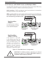
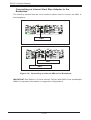
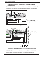
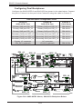
C-11Failover
The SAS2-837EL2 backplane has two expanders which allow effective failover.
SAS HBA
MH6
C861
MH8
EC35
C
L153
EC36
A
ACT25
EC20
+
+
A1
33
+
+
WWN
A1
16
17
+
+
B18
U1
C864
Q3
15
PRI_J0
MH13
EC4
+
10
+
B1
PRI_FLASH
+
+
EC10
+
5
J1
+
E
K
R
Y
AE
C863
+
+
C865
L151
WWN
C866
BCA534
BCA420
J0
AH
C
B18
+
ACT24
A
PRI_J4
B1
L152
EC26
J24
+
U16
BC52
C862
MH9
+
EC22
+
EC28
MH12
U17
1
20
C2988
B18
SEC_J2
B1
8
28
MH3
A1
MH7
U6
A18
C
1
C
1
+
B18
GND
GND
U5
+5V
U312
MH4
PWR1
+12V
+5V
+
GND
DESIGNED IN USA
EC2
UART_S
4
SEC_FLASH
+
A
BAR CODE
A
BPN-SAS2-837EL2
GND
J0
Y
B1
FAN3
EC1
1
RA611
4
MH10
1
FAN2
Secondary ports
Expander 2
TOLERANCES
DECIMAL
ANGLE
X .1
30
XX .03
MACH FINISH
XXX.010
REV: 1.00
EC19
1
K
Primary ports
Expander 1
8-10-2010
4
1
B1
PWR2
+12V
5
UNLESS OTHERWISE
SPECIFIED DIMENSIONS
ARE IN INCHES
Layout Team 1
H/W:Shen Ping
DESINGER:
DESIGNED BY SUPERMICRO U.S.A.
www.supermicro.com
DATE:
SAN JOSE,CA 95131
PROJECT NAME:
TEL:408-503-8000 FAX:408-503-8008
B1
EXPDBG2
4
4
EXPDBG1
1
Q2
10
SEC_J4
Q1
EC17
+5V
+
L148
L147
C430
SUPER
SILKSCREEN
PRIMARY-SIDE
15
C2971
MH1
FAN1
RR
GND
U332
C2970
+
+
MH11
GND
SEC_J0
C871
+12V
EC13
+
U4
J1
PWR3
C868
B18
+
EC18
+5V
+
GND
+
+
25
+
+
L1
A18
+
GND
+
C867
Y10
28
B18
20
+12V
B18
1
+
PRI_J2
B1
PWR4
A1
UART_P
L398
BC91
MH5
FANFAIL1
OVERHEATFAIL1
A18
EC16
BC92
EC15
A1
EC8
+
C377
C870
FANFAIL_LED_DISABLE
B18
SEC_J3
PRI_J1
+
B1
+
C2973
REV: 1.00
+
ACTLED1
BPN-SAS2-837EL2
FAN_MONITOR_DISABLE
B18
1
C
C2972
MH2
C
5V_LED
A
J25
EC3
L149
A18
+
PRI_J3
B1
12V_LED
A
EC25
EC9
25
+
EC27
PRI_I2C
PRI_I2C1
+
In a single host bus configuration,
the backplane connects to one
Host Bus Adapter (HBA).
+
Single Host Bus
Adapter
SAS HBA
J1
MH6
C861
MH8
C
C864
L153
EC36
A
ACT25
EC20
+
+
A1
10
17
+
+
+
+
A1
16
Q3
15
B18
U1
5
PRI_J0
MH13
EC4
+
EC35
E
K
R
Y
+
B1
+
+
EC10
+
C863
+
+
BCA420
C865
L151
WWN
C866
+
J0
PRI_FLASH
L152
EC26
AE
BCA534
AH
C
B18
+
ACT24
A
PRI_J4
B1
+
J24
C862
MH9
U16
BC52
EC22
+
EC28
MH12
+
33
WWN
U17
1
20
C2988
B18
SEC_J2
B1
8
28
MH3
A1
MH7
U6
A18
1
C
+
SEC_FLASH
MH4
PWR1
+12V
+5V
J0
B18
GND
GND
U5
+5V
U312
Y
GND
+
K
GND
DESIGNED IN USA
1
C
+
A
BAR CODE
A
EC2
UART_S
4
B1
PWR2
+12V
B1
EC1
1
FAN3
4
1
FAN2
Secondary ports
Expander 2
Figure C-6: Single HBA Failover Configurations
C-11
EC19
1
BPN-SAS2-837EL2
TOLERANCES
DECIMAL
ANGLE
X .1
30
XX .03
MACH FINISH
XXX.010
B1
EXPDBG2
4
1
REV: 1.00
4
1
+
Layout Team 1
H/W:Shen Ping
8-10-2010
5
SEC_J4
10
Primary ports
Expander 1
DESINGER:
DESIGNED BY SUPERMICRO U.S.A.
www.supermicro.com
DATE:
SAN JOSE,CA 95131
PROJECT NAME:
TEL:408-503-8000 FAX:408-503-8008
4
EXPDBG1
+
Q2
15
+5V
+
Q1
GND
C2971
L148
L147
C430
SUPER
EC17
UNLESS OTHERWISE
SPECIFIED DIMENSIONS
ARE IN INCHES
GND
U332
C2970
MH1
FAN1
+
+
MH11
SILKSCREEN
PRIMARY-SIDE
B18
+
U4
+12V
EC13
RR
J1
PWR3
C868
B18
+
EC18
+5V
+
GND
SEC_J0
25
+
+
L1
A18
+
GND
1
C871
28
B18
20
+12V
UART_P
+
PRI_J2
B1
PWR4
A1
C867
Y10
+
L398
BC91
MH5
FANFAIL1
OVERHEATFAIL1
A18
EC16
BC92
EC15
A1
EC8
+
C377
C870
FANFAIL_LED_DISABLE
B18
SEC_J3
PRI_J1
+
B1
+
C2973
REV: 1.00
+
ACTLED1
BPN-SAS2-837EL2
FAN_MONITOR_DISABLE
B18
1
C
J25
C2972
MH2
C
5V_LED
A
EC3
L149
A18
+
PRI_J3
B1
12V_LED
A
EC25
EC9
25
+
EC27
PRI_I2C
PRI_I2C1
+
If the expander or data path in
the primary ports fails, the system
automatically switches to the secondary ports.
+
Single Host Bus
Adapter Failover
RA611
MH10
SC837J Chassis Manual
C-12Failover with RAID Cards and Multiple HBAs
The SAS-837EL2 backplane may be configured for failover with multiple HBAs using
either RAID controllers or HBAs to acheive failover protection.
RAID Controllers: If RAID controllers are used, then the failover is accomplished
through port failover on the same RAID card.
HBAs: If multiple HBAs are used to achieve failover protection and load balancing,
Linux MPIO software must be installed and correctly configured to perform
the load balancing and failover tasks.
SAS HBA
SAS HBA
L151
MH8
MH13
EC4
+
EC35
C
C864
L153
A
ACT25
U1
5
EC36
EC20
+
+
A1
10
17
33
+
+
+
+
WWN
A1
16
Q3
15
B18
+
+
EC10
+
E
K
R
J1
+
C863
+
+
C865
Y
PRI_J0
U17
1
20
C2988
B18
SEC_J2
B1
8
28
MH3
A1
+
C
C
1
A
GND
1
+
PWR1
+12V
+5V
B18
GND
GND
U5
+5V
U312
MH4
+
Y
DESIGNED IN USA
EC2
UART_S
4
SEC_FLASH
+
A
BAR CODE
1
EC19
1
B1
EXPDBG2
4
+
8-10-2010
4
1
GND
J0
5
K
SEC_J4
DESINGER:
DESIGNED BY SUPERMICRO U.S.A.
www.supermicro.com
DATE:
EXPDBG1
B1
PWR2
+12V
10
UNLESS OTHERWISE
SPECIFIED DIMENSIONS
ARE IN INCHES
Layout Team 1
H/W:Shen Ping
SAN JOSE,CA 95131
PROJECT NAME:
TEL:408-503-8000 FAX:408-503-8008
Q2
15
+5V
+
L148
SILKSCREEN
PRIMARY-SIDE
L147
RR
C430
SUPER
Q1
EC17
GND
C2971
+
+
FAN1
GND
U332
C2970
+12V
EC13
MH1
+
U4
J1
PWR3
C868
B18
+
EC18
+5V
+
GND
SEC_J0
C871
25
+
+
L1
A18
+
GND
+
+
28
B18
20
+12V
FANFAIL1
OVERHEATFAIL1
C867
Y10
PRI_J2
B1
PWR4
MH11
4
1
L398
BC91
B18
UART_P
+
EC16
BC92
A1
FANFAIL_LED_DISABLE
A18
EC15
MH5
EC8
+
C377
C870
FAN_MONITOR_DISABLE
B18
SEC_J3
PRI_J1
+
B1
A1
+
C2973
REV: 1.00
A18
+
BPN-SAS2-837EL2
ACTLED1
C
MH7
U6
1
A
EC25
C2972
MH2
B18
C
5V_LED
J25
EC3
L149
A18
PRI_I2C1
PRI_J3
B1
12V_LED
A
EC9
25
PRI_I2C
+
EC27
+
In a dual host bus configuration, the backplane connects
to two Host Bus Adapters.
MH6
C861
AE
B1
PRI_FLASH
L152
WWN
C866
BCA534
BCA420
J0
AH
C
B18
+
ACT24
A
PRI_J4
B1
C862
EC26
J24
BC52
+
U16
+
MH9
+
EC22
+
EC28
MH12
+
Dual Host Bus
Adapter
B1
FAN3
EC1
1
RA611
4
MH10
1
FAN2
TOLERANCES
DECIMAL
ANGLE
X .1
30
XX .03
MACH FINISH
XXX.010
REV: 1.00
BPN-SAS2-837EL2
Secondary ports
Expander 2
Primary ports
Expander 1
SAS HBA
Dual Host Bus
Adapter Failover
SAS HBA
1
8
C
1
C
+
SEC_FLASH
GND
PWR1
+12V
+5V
GND
GND
U5
+5V
U312
+
B18
+
GND
DESIGNED IN USA
1
A
BAR CODE
A
+
16
1
1
+
FANFAIL1
OVERHEATFAIL1
FANFAIL_LED_DISABLE
FAN_MONITOR_DISABLE
EC2
UART_S
4
SEC_J4
C2971
+
L148
L147
SAN JOSE,CA 95131
PROJECT NAME:
TEL:408-503-8000 FAX:408-503-8008
Q2
EC19
U332
B1
EC1
FAN3
1
4
RA611
MH10
Y
MH4
FAN2
UNLESS OTHERWISE
SPECIFIED DIMENSIONS
ARE IN INCHES
Layout Team 1
H/W:Shen Ping
8-10-2010
C430
DESINGER:
DESIGNED BY SUPERMICRO U.S.A.
www.supermicro.com
DATE:
Q1
B1
EXPDBG2
4
B1
PWR2
+12V
5
+
UPER
4
1
MH7
C2970
+5V
K
MH1
EC17
4
EXPDBG1
SEC_J0
GND
1
C871
15
GND
+
+
+12V
1
MH11
FAN1
B18
UART_P
+
U4
+
+
A18
PWR3
C868
B18
+
EC18
10
SILKSCREEN
PRIMARY-SIDE
A1
C867
25
+
+
L1
EC13
RR
+
SEC_J3
+
Y10
+
28
B18
+5V
MH5
EC8
A18
L398
GND
A1
+
C2973
A18
+
C377
C870
20
GND
17
C2972
+
B18
J25
+
ACTLED1
PRI_J1
EC16
PRI_J2
B1
PWR4
+12V
U1
+
+
1
+
B1
BC92
!
+
+
U6
REV: 1.00
BC91
EC3
L149
A18
MH2
B18
C
5V_LED
A
ACT25
U17
B1
28
PRI_J3
B1
SEC_J2
EC9
25
+
MH3
A1
EC15
C
33
WWN
20
C2988
EC27
EC25
A1
B18
PRI_I2C
BPN-SAS2-837EL2
EC4
EC35
+
B18
MH13
Q3
15
PRI_J0
PRI_I2C1
C
A1
10
+
B1
PRI_FLASH
A
EC36
EC20
BCA534
12V_LED
A
L153
5
B18
+
+
C864
C
PRI_J4
B1
+
+
EC10
+
E
K
R
Y
AE
AH
ACT24
A
C863
+
+
BCA420
+
C865
MH8
C862
MH6
C861
C866
J24
BC52
L151
WWN
EC26
+
U16
+
MH9
+
+
EC28
MH12
EC22
L152
If the expander or data pa