1
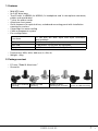
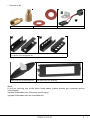
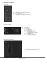
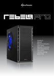
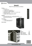
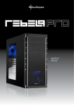
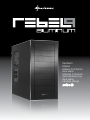
Handbuch Manual Manuel d‘utilisation Guia usario Manuale d´istruzioni Gebruiksaanwijzing Guia usário Instukcja obstugi 使用手冊 REBEL9 ALU U3 1 Content 1. Features 2. Package content 3. The case at a glance 4. Installation of a mainboard 5. Installation of a PSU 6. Installation of a HDD 7. Installation of an optical device 8. Installation of a 3.5" device 9. Installation of an add-on card 10. The pre-installed fan 11. Installation of additional fans / optimized airflow 3 3 5 7 9 10 11 13 14 15 15 Dear customer! Congratulations for purchasing this premium quality SHARKOON product. For a long life time and to take full advantage of this product we recommend that you read this manual completely. Have a good time with our product! SHARKOON Technologies REBEL9 ALU U3 2 1.Features • • • • • • • • • Midi ATX case 9x 5.25" drive bays Top I/O with 1x USB3.0, 2x USB2.0, 1x headphone and 1x microphone connector, power and reset button 7 slots for add-on cards Aluminum front panel Quick fasteners for optical drives, mainboard mounting panel with installation opening for coolers 2 openings for water cooling Cable management system Fan configuration: Case front Side panel Back side Top panel 1x 120 mm fan with 3-pin and 4-pin connector (pre-installed) 2x 120 mm fan (optional) 1x 80 mm or 1x 120 mm fan (optional) 1x 120 mm or 1x 140 mm fan (optional) • Dimensions: 455 x 202 x 440 mm (L x W x H) • Weight: ~6 kg 2.Package content • PC case “Rebel 9 Aluminum” • Screw kit: Screws for mainboard Screws for PSU mounting mounting Screws for drive Screws for HDD mounting mounting (3.5" and 5.25") REBEL9 ALU U3 3 • Accessory kit: A B Stand-offs for mainboard Washers A Lock attachment (A) and speaker (B) B Mounting angles for HDDs (decoupled / A) and 3.5" devices (not decoupled / B) Quick fasteners for optical drives 5.25" bezel with 3.5" opening Note: If you are missing any of the items listed above, please contact our customer service immediately: [email protected] (Germany and Europe) [email protected] (international). REBEL9 ALU U3 4 3.The case at a glance Front view A B A – LEDs for power and HDD activity B – 5.25" drive bays C – covered: pre-installed 120 mm fan C View from above B c d e a A b A – Fan bracket B – Top I/O with: a – Power and b – Reset button, c – 1x headphone and 1x microphone connector d – 2x USB2.0 and e – 1x USB3.0 connector Side view (closed/left) A A – Brackets for two 120 mm fans REBEL9 ALU U3 5 Side view (opened/left) A B a A – Drive bays for 5.25" devices B – Mainboard mounting panel with: a – Installation opening for coolers and b – Cable management system CPU b Back side view A B F F A – Opening for I/O shield B – Fan bracket C – Slot bezels D – Openings for water cooling E – PSU bracket F – Thumb screws C D E F F Bottom view A A A – Case feet B B – Air intake for PSU A A Note: For more information on how to install the intended devices, refer to their respective documents. REBEL9 ALU U3 6 4.Installation of a mainboard 1. Open the case by loosening the thumb screws on the case’s back side and removing the left side panel. Lay down the case sidewise on an even surface. 2. The mainboard’s mounting panel inside the case provides various drillings to fix the stand-offs (fig. 1). fig. 1 The mainboard contains special screw openings (fig. 2). fig. 2 Place the mainboard to the mounting panel. A stand-off must be screwed into every drilling of the mounting panel visible through the mainboard’s screw openings. REBEL9 ALU U3 7 3.Remove the mainboard and screw the stand-offs into the respective drillings of the mounting panel (fig. 3). (Stand-offs) fig. 3 4. Press the I/O shield (delivered with the mainboard) into the I/O shield opening in the case’s back side. 5. Place the mainboard back onto the stand-offs and screw the mainboard to them (fig. 4). (Screws for mainboard mounting) fig. 4 REBEL9 ALU U3 8 6. Plug the connectors of the case’s front bezel to the respective connectors of the mainboard (also refer to your mainboard’s manual for further information). 5.Installation of a PSU 1. Set up the case in front of you and put the PSU from the inside against the PSU bracket on the case’s back side (fig. 5). fig. 5 2. Screw the PSU to the case from the outside (fig. 6). (Screws for PSU mounting) fig. 6 REBEL9 ALU U3 9 6.Installation of a HDD 1. Remove the case’s right side panel. 2. Attach the decoupled mounting angles to the HDD from both sides (fig. 7). (Screws for HDD mounting) (Decoupled mounting angles) fig. 7 3.Slide the HDD with attached mounting angles into the case’s respective drive bay and screw it from both sides (fig. 8). fig. 8 4. Connect the HDD to the power supply and the mainboard. REBEL9 ALU U3 10 7. Installation of an optical device 1. Remove the case’s front panel by gently dragging it towards you (fig. 9). fig. 9 2. Dismantle the 5.25" front bezel from the mounting bay in which you intend to install the drive by loosening its screws and pushing the bezel to the inside (fig. 10). Remove the quick fasteners (fig. 11). fig. 10 fig. 11 (Carefully take out an optionally present metal bezel covering the 3.5" drive bay by using a gripper.) 3. Slide the optical drive into the case’s drive bay (fig. 12). fig. 12 REBEL9 ALU U3 11 4. Attach the optical device from both sides using the quick fasteners (fig. 13). fig. 13 Note: If you intend to transport the case we recommend securing (additionally) the installed drives: (Screws for 5.25" drive mounting) 5. Connect the optical drive to the power supply and the mainboard. (Put the front bezel back onto the case.) 8.Installation of a 3.5" device (1.Remove the case’s front panel by gently dragging it towards you.) 2.Dismantle the 5.25" front bezel from the mounting bay in which you intend to install the drive by loosening its screws and pushing the bezel to the inside (fig. 14). Remove the quick fasteners (fig. 15). fig. 14 fig. 15 REBEL9 ALU U3 12 (Carefully take out an optionally present metal bezel covering the drive bay by using a gripper.) 3. Screw the mounting angles to the 3.5" device from both sides (fig. 16). fig. 16 4.Slide the 3.5" device with attached mounting rails into the case’s drive bay (fig. 17) and screw it to the drive bay from both sides (fig. 18). fig. 17 fig. 18 5. Connect the 3.5" device to the power supply and the mainboard. 6. Screw the 5.25" bezel with 3.5" opening into the front panel (fig. 19) and place it back onto the case. (5.25" bezel with 3.5" opening) fig. 19 REBEL9 ALU U3 13 9.Installation of an add-on card 1. Remove the slot bezel’s fixation screw and take away the slot bezel (fig. 20). fig. 20 2.Insert the add-on card into the mainboard’s respective slot and fix it to the case by re-attaching the fixation screw (fig. 21). fig. 21 10. The pre-installed fan 1. The pre-installed 120 mm front fan provides a 4-pin PSU connector and a 3-pin mainboard plug. 2. Connect one of both plugs to either the respective PSU or (to control the fan speed via the mainboard) the matching mainboard connector. REBEL9 ALU U3 14 11. Installation of additional fans / optimized airflow 1. Place the fan against the respective bracket from the inside (e.g. in the top panel / fig. 22). fig. 22 2. Screw the fan to the attachment from the outside (fig. 23). fig. 23 Note: The Rebel 9 Aluminum case offers a lot of possibilities to install fans. While installing fans make sure that (cool) air is taken in on the case’s front side/bottom and blown out on its back side/top. The PC components with the highest heat development should be placed directly within the airflow. REBEL9 ALU U3 15 Legal disclaimer: As a continuing policy of product improvement at SHARKOON, the design and specifications are subject to change without prior notice. National product specifications may vary. All rights reserved especially (also in extracts) for translation, reprinting, reproduction by copying or other technical means. Infringements will lead to compensation. All rights reserved especially in case of assignation of patent or utility patent. Means of delivery and technical modifications reserved. Disposal of your old product Your product is designed and manufactured with high quality materials and components, which can be recycled and reused. When this crossed-out wheeled bin symbol is attached to a product, it means the product is covered by the European Directive 2002/96/EC. Please be informed about the local separate collection system for electrical and electronic products. Please act according to your local rules and do not dispose of your old products with your normal household waste. The correct disposal of your old product will help prevent potential negative consequences to the environment and human health. © SHARKOON Technologies 2012 www.sharkoon.com REBEL9 ALU U3 16