1
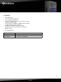
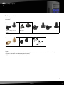
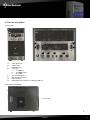
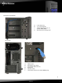
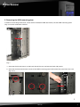
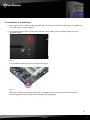
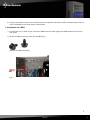
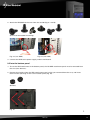
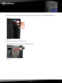
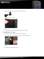
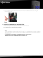
Manual MS140 Content 1. Features 3 2. Package content 4 3. The case at a glance 5 4. Installation notes 7 5. Removing the left HDD mounting plate 8 6. Installation of a mainboard 9 7. Installation of a PSU 11 8. Installation of a HDD 12 8.1 Into the lateral HDD mountings 12 8.2 Into the bottom panel 13 9. Installation of an optical device 14 10. Installation of a 3.5" device 16 11. Installation of an add-on card 17 12. Installation of additional fans / optimized airflow 18 Dear customer! Congratulations for purchasing this premium quality SHARKOON product. For a long life time and to take full advantage of this product we recommend you to read this manual completely. Enjoy our product! SHARKOON Technologies MS140 2 1. Features • • • • • • • • • • Micro ATX case 1x 5.25" drive bay (external) 1x 3.5" drive bay (external) Internal mounting area for 4x 3.5“ or 6x 2.5“ HDDs 4 slots for add-on cards Front I/O with 1x USB3.0, 3x USB2.0 and 2x audio 1x 140 mm LED fan pre-installed Supports VGA cards up to 36 cm length Dimensions: 420 x 175 x 368 mm (L x W x H) Weight: ~4 kg • Fan configuration: Case front 1x 140 mm LED fan Rear panel 1x 80 mm or 1x 92 mm fan (optional) Case bottom 1x 120 mm fan (optional) MS140 3 2. Package contents • ATX case „MS140“ • Screw kit: Screws for mainboard and drive mounting (3.5" and 5.25") Mounting screws for 2.5" HDDs/SSDs Screws for PSU mounting Screws for HDD mounting • Accessory kit: A B Stand-offs for mainboard Washers Cable tie (A) and speaker (B) Note: If you are missing any of the items listed above, please contact our customer service immediately: [email protected] (Germany and Europe) [email protected] (international). MS140 4 3. The case at a glance Front panel A B A E B F E C H G a b c b D A – B – C – D – E– F– G – H – 5.25" drive bay Power LED On/off button Front I/O: a – 1x USB3.0 b – 3x USB2.0 and c – 2x audio 3.5" mounting bay LED for HDD activity Reset button behind the mesh panel: 1x 140 mm LED fan Side panel (closed/left) A – Air inlet A MS140 5 Side panel (opened/left) A B A – B – C – D – C D 5.25" drive bay 3.5" mounting bay Attachments for 4x 3.5" or 6x 2.5"-HDDs/SSDs Mainboard mounting panel Rear panel A E E B C F D E E A – B – C – D – E– F– PSU bracket Opening for I/O shield Fan bracket (80 or 92 mm) Slot bezels Thumb screws Connection cable for the front USB3.0 plug MS140 6 Bottom panel A B A B D C C B A A – B – C – D – B A Case feet Attachment for 3.5“ HDD Attachment screws for HDD mounting panel Bracket for 120 mm fan 4. Installation notes 1. For further information on how to install the PC components, also refer to their respective instructions. 2. In order to install long VGA cards, it might be necessary to remove the left HDD mounting panel (see 5.). To have the option to install at least two 3.5“ HDDs, there is an additional HDD attachment in the bottom panel of the case. MS140 7 5. Removing the HDD mounting plate In order to install long VGA cards, and to utilize the bottom HDD attachment, the left HDD mounting panel (fig. 1) must be removed as follows: Fig. 1 1. Unscrew the thumb screws on the back side of the case and remove both side panels. 2. Unscrew the three attachment screws of the HDD mounting panel and remove the panel from the case (fig. 2 a-c). Fig. 2 a-c MS140 8 6. Installation of a mainboard 1. Unscrew the thumb screws on the back side of the case and remove the left side panel. Lay down the case sidewise on an even surface. 2. The mounting panel of the mainboard inside the case provides various mounting holes to fix the standoffs (fig. 3). Fig. 3 The mainboard contains special screw mounts (fig. 4). Fig. 4 Place the mainboard to the mounting panel. A standoff must be screwed into every hole on the mounting panel visible through the mainboard’s screw openings. MS140 9 3. Remove the mainboard and screw the standoffs into the respective holes of the mounting panel (fig. 5). (Standoffs) Fig. 5 4. Insert the I/O shield (delivered with the mainboard) into the I/O shield opening in the rear panel of the case. 5. Place the mainboard back onto the standoffs and screw the mainboard to them (fig. 6). (Screws for mainboard mounting) Fig. 6 MS140 10 6. Plug the connectors of the case’s front bezel to the respective connectors of the mainboard (also refer to your mainboard’s manual for further information). 7. Installation of a PSU 1. Position the case in front of you and set the PSU from the inside against the PSU bracket on the case’s rear panel. 2. Screw the PSU to the case from the outside (fig. 7). (Screws for PSU mounting) Fig. 7 MS140 11 8. Installation of a HDD 8.1 Into the lateral HDD mountings A B A – Attachments for 3.5" HDDs (decoupled mounting) B – Attachments for 2.5" HDDs/SSDs Note: Prior to the 2.5"HDD/SSD installation, the buffers for 3.5" HDDs must be removed from the attachments. 1. Hold the HDD/SSD against the respective attachment (fig. 8 a and b). Fig. 8 a (3.5" HDD) Fig. 8 b (2.5" HDD) MS140 12 2. Attach the HDD/SSD to the case from the outside (fig. 9 a and b). (Screws for drive/HDD mounting) Fig. 9 a (3.5" HDD) Fig. 9 b (2.5" HDD) 3. Connect the HDD to the power supply and the mainboard. 8.2 Into the bottom panel 1. To use the HDD attachment in the bottom panel, the left HDD attachment panel must be removed from the case (see above 5.). 2. Remove four buffers from the HDD attachment panel, which you removed from the case, and insert them into the openings on the case‘s bottom panel (fig. 10). (Buffers) Fig. 10 MS140 13 3. Place the HDD onto the buffers and attach it to the case from the outside (fig. 11 a and b). Fig. 11 a und b 4. Connect the HDD to the power supply and the mainboard. 9. Installation of an optical device 1. Remove the case’s front panel by gently pulling it towards you (fig. 12). Fig. 12 MS140 14 2. Dismantle the 5.25" front bezel from the mounting bay by pushing it out of the front panel (fig. 13). 3. Place the front panel back onto the case. 4. Slide the optical drive into the case’s drive bay (fig. 14). Fig. 13 Fig. 14 MS140 15 5. Attach the optical device to the case from both sides (fig. 15). (Screws for drive mounting) Fig. 15 6. Connect the optical drive to the power supply and the mainboard. 10. Installation of a 3.5" device 1. Remove the case’s front panel by gently pulling it towards you. 2. Dismantle the 3.5" front bezel by pushing it out of the front panel (fig. 16). 3. Place the front panel back onto the case. Fig. 16 MS140 16 4. Slide the 3.5" device into the 3.5" mounting bay and attach it from both sides (fig. 17). (Screws for 5.25" drive mounting) Fig. 17 5. Connect the 3.5" device to the power supply and the mainboard. 11. Installation of an add-on card 1. Remove the anchor screw of the slot bezel and take it from the case (fig. 18). Fig. 18 MS140 17 2. Insert the add-on card into the respective slot of the mainboard and attach it to the case using the anchor screw (fig. 19). Fig. 19 12. Installation of additional fans / optimized airflow 1. Place the fan against the respective bracket from the inside of the case. 2. Screw the fan to the attachment from the outside. Notes: 1. When installing fans, make sure that (cool) air is taken in on the front/bottom of the case and blown out on its rear side/top. The PC components with the highest heat development should be placed directly within the airflow. 2. The installation of the lower fan is an additional application for VGA cooling. The bottom PCI slot of the mainboard will be occupied when used. MS140 18 Legal disclaimer: As a continuing policy of product improvement at SHARKOON, the design and specifications are subject to change without prior notice. National product specifications may vary. All rights reserved especially (also in extracts) for translation, reprinting, reproduction by copying or other technical means. Infringements will lead to compensation. All rights reserved especially in case of assignation of patent or utility patent. Means of delivery and technical modifications reserved. Disposal of your old product Your product is designed and manufactured with high quality materials and components, which can be recycled and reused. When this crossed-out wheeled bin symbol is attached to a product, it means the product is covered by the European Directive 2002/96/EC. Please be informed about the local separate collection system for electrical and electronic products. Please act according to your local rules and do not dispose of your old products with your normal household waste. The correct disposal of your old product will help prevent potential negative consequences to the environment and human health. © SHARKOON Technologies 2011 www.sharkoon.com MS140 19