1
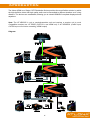
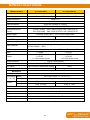
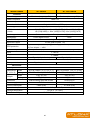
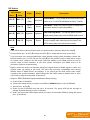
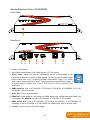
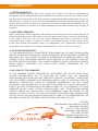
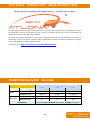
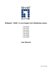
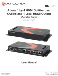
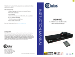
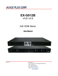
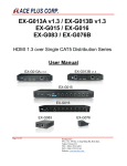
AtlonA HDMI™ v1.3 over Single CAT5E/6 Distribution Series User’s Manual AT-HD50SS AT-HDRS AT-HD50RSL AT-HD15SRS Rev.1007 TABLE OF CONTENTS 1. Introduction ....................................................................... 1 2. Features ....................................................................... 2 3. Package Contents ....................................................................... 2 4. Specifications ....................................................................... 3 5. Panel Descriptions ....................................................................... 5 5.1 Sender Unit AT-HD50SS .............................................................. 5 5.2 Sender / Receiver Unit AT-HD50RSL ............................................ 7 5.3 Receiver Unit AT-HDRS .............................................................. 8 5.4 Receiver Unit AT-HD15SRS .......................................................... 8 6. Installation ....................................................................... 9 6.1 AT-HD50SS ...................................................................... 9 6.2 AT-HD50RSL ....................................................................... 9 7. Notice ....................................................................... 11 8. RJ45/CAT5 Reference ...................................................................... 11 9. Safety Information 10. Warranty ..................................................................... 12 ...................................................................... 13 11. Atlona Product Registration .................................................................. 14 12. Performance Guide ...................................................................... 14 INTRODUCTION The Atlona HDMI over Single CAT5 Distribution Series provides the most flexible solution by which the high definition video and high quality audio can be transmitted to different locations over a long distance. The devices are cascadable, allowing you to extend HDMI/DVI compliant displays almost anywhere. Note: The AT-HD50SS is only a sender/transmitter unit and requires a receiver unit to work. Compatible receives are: AT-HDRS (CAT5/6 in and HDMI out) or AT-HD50RSL (Cat5/6 input, CAT5/6 loop-out for further cascading, HDMI output) Diagram: 1 FEATURES Silicon Image Chip-Sets allow 99.99% compatibility with all the AV gear (we only use Best) HDMI 1.3c compliant HDCP compliant Regenerates the HDMI signal, so there is no signal loss Supports Analog and Digital Audio Supports default HDMI EDID and has the ability to learn the EDID of displays Extends up to 60m (200ft) (720p / 1080i) of output CAT5/6 cable Extends up to 40m (130ft) (1080p) of output CAT5/6 cable Minimizes the cable skew by adjustable 8-level equalization control Pure unaltered uncompressed 7.1ch digital HDMI over CAT5/6 cable transmission Allows cascading Compatible with different receiver options: AT-HDRS and AT-HD50RSL Note: Atlona recommends to use Cat6 or Cat5e cables for better performance. Atlona recommends to always use "Type B" termination for the Cat6 or Cat5 Cables to extend the distance. PACKAGE CONTENTS AT-HD50SS 1x AT-HD50SS unit 1x 5V DC locking power supply unit (universal) 1x User's manual AT-HD50RSL 1x AT-HD50RSL unit 1x 5V DC locking power supply unit (universal) 1x User's manual 2 SPECIFICATIONS Model Name AT-HD50SS AT-HD50RSL Sender (TX) Sender / Receiver (TRX) Technical Role of usage HDMI compliance HDMI 1.3c HDCP compliance Yes Video bandwidth Video support Single-link 225MHz (6.75Gbps) 480i / 480p / 720p / 1080i / 1080p60 24/30/36-bit color HDMI transmission (24-bit) Audio support Full HD (1080p) 40m (130ft) [CAT5e] / 50m (165ft) [CAT6] HD (720p/1080i) 50m (165ft) [CAT5e] / 60m (200ft) [CAT6] Surround sound (up to 7.1ch) or stereo digital audio Equalization None 8-level digital control Input TMDS signal 1.2 Volts (peak-to-peak) Input DDC signal 5 Volts (peak-to-peak, TTL) ESD protection [1] Human body — ±19kV (air-gap discharge) & ±12kV (contact discharge) [2] Core chipset — ±8kV PCB stack-up 4-layer board (impedance control — differential 100; single 50) Input 1 x HDMI 1 x RJ-45 1 x HDMI 1 x RJ45 1 x 3.5mm audio socket Output 1 x HDMI 1 x RJ-45 1 x 3.5mm audio socket HDMI connector Type A (19-pin female) RJ45 connector WE/SS 8P8C with 2 LED indicators DIP switch Rotary control switch 2-pin for EDID & audio/video setting None None Signal equalization Mechanical Housing Metal enclosure Dimensions Model [L x W x H] Package Weight 180 x 108 x 27mm (7" x 4.3" x 1.1") 330 x 200 x 95mm (1’1" x 8" x 4") Model 515g (1.1 lbs) 515g (1.1 lbs) Package 970g (2.1 lbs) 970g (2.1 lbs) Fixedness Wall-mounting case with screws Power supply 5V DC Power consumption 1 Watt [max] Operation temperature 0~40C (32~104F) Storage temperature Relative humidity -20~60C (-4~140F) 20~90% RH (no condensation) 3 Model Name AT-HDRS AT-HD15SRS Receiver (long range RX) Receiver (short range RX) Technical Role of usage HDMI compliance HDMI 1.3c HDCP compliance Video bandwidth Yes Single-link 225MHz (6.75Gbps) Video support 480i / 480p / 720p / 1080i / 1080p60 24/30/36-bit color HDMI transmission (24-bit) Full HD (1080p) — 40m (130ft) [CAT5e] / 50m (165ft) [CAT6] HD (720p/1080i) — 50m (165ft) [CAT5e] / 60m (200ft) [CAT6] Audio support Surround sound (up to 7.1ch) or stereo digital audio Equalization 8-level digital control Input TMDS signal None 1.2 Volts (peak-to-peak) Input DDC signal 5 Volts (peak-to-peak, TTL) ESD protection [1] Human body — ±19kV (air-gap discharge) & ±12kV (contact discharge) [2] Core chipset — ±8kV PCB stack-up 4-layer board (impedance control — differential 100; single 50) Input 1 x RJ-45 Output 1 x HDMI HDMI connector RJ45 connector Rotary control switch Type A (19-pin female) Type A (19-pin male) WE/SS 8P8C with 2 LED indicators Signal equalization None Mechanical Housing Dimensions [L x W x H] Weight Metal enclosure Model Package Model Package Fixedness Power supply Power consumption 85 x 90 x 25mm (3.3" x 3.5" x 1") 45 x 25 x 20mm (1.8" x 1" x 0.8") 175 x 270 x 80mm (6.9"x10.6"x3.2") 115 x 170 x 40mm (4.5"x6.7"x1.6") 175g (6.2 oz) 22g (0.8 oz) 475g (1 lb) 90g (3.2 oz) Wall-mounting case with screws Direct plug-in 5V DC None 1 Watt (max) 0.5 Watt (max) Operation temperature 0~40C (32~104F) Storage temperature Relative humidity -20~60C (-4~140F) 20~90% RH (no condensation) 4 PANEL DESCRIPTIONS Sender Unit AT-HD50SS Front Panel 1 Rear Panel 2 3 4 5 6 7 8 1. Power on/off indicator 2. Input video format indicator (ON: HDMI signal / OFF: DVI signal) 3. DIP switch (see the table in the next page) 4. HDMI IN: Connect to a HDMI source with a HDMI male-male cable 5. Audio OUT: Plug in a local speaker 6. HDMI OUT: Local HDMI for connecting to a HDMI display with a HDMI male-male cable, or cascade to the HDMI IN of another AT-HD50SS, AT-HD14SS, or AT-HD19SS, or link to a remote display with AT-HDRS or AT-HD15SRS via a Cat.5e/6 cable 7. HDMI Signal OUT: Link to AT-HD50RSL for cascading; or link to AT-HDRS or AT-HD15SRS to another HDMI display via a Cat.5e/6 cable 8. +5V DC: Connect to a 5V 4A DC power supply unit 5 DIP Switch Pin Position Video Audio OFF () Up to 1080p Surround1 Default Mode2 – Up to 1080p & surround sound audio output up to 7.1ch (DTS-HD Master & Dolby TrueHD) OFF () ON () Up to 1080p Stereo Safe Mode3 – Make the system output at 1080p video and stereo audio for basic compatibility ON () OFF () Bypass4 Bypass4 EDID Learning Mode5 – for learning EDID from the display while playing any received HDMI audio format Stereo EDID Learning & Stereo mode5 – for learning EDID from the display while enforcing stereo output if any HDTV cannot play surround sound normally Pin-1 Pin-2 OFF () ON () ON () Bypass Description Note 1 If the HDTV shows video but without audio, set audio mode to stereo by dial pin-2 to ON[]. 2 Factory default: pin-1 at OFF () and pin-2 at OFF () for 1080p with surround sound audio. 3 If you encounter any unsolved audio/video output problem during system installation, please dial the DIP switch to pin 1 at OFF (), pin 2 at ON () for safe mode to enforce 1080p stereo output for system check. However, the safe mode cannot be initiated if your HDMI sources are set to enforce output at fixed resolution. In this case, please reconfigure your HDMI source to all resolutions output for troubleshooting. 4 Bypass means this device will maintain playing the original format of HDMI signals in video and perhaps audio. By setting at this mode, the users may encounter compatibility issue among different kinds of HDMI sources and displays. If you cannot get the audio and/or video output normally at the system installation, please change the DIP switch setting to default mode or even safe mode to verify the functionality of the device. 5 Steps for EDID (Extended Display Identification Data) learning A. Power off the AT-HD50SS. B. Connect the display which you want to read EDID to HDMI OUT port on the AT-HD50SS. C. Set DIP pin-1 at ON (). D. Power on the AT-HD50SS and wait up to 20 seconds. The green LED will dim and light to indicate the EDID learning process is complete. E. DON’T pull up the DIP switch again unless you want to learn another EDID by pulling DIP switch pin-1 up and down. 6 Sender/Receiver Unit AT-HD50RSL Front Panel 1 Rear Panel 2 3 4 5 6 7 8 1. Power on/off indicator 2. Input video format indicator (ON: HDMI signal / OFF: DVI signal) 3. Signal Level: Adjust the 16-level equalization control corresponding to the transmission distance of receiving HDMI signals. For surround sound audio output, please adjust from 0-to-7 (longest-to-shortest transmission length). For stereo audio output, please adjust from 8-to-F (longest-to-shortest transmission length). It is recommended to adjust from 7-to-0 or from F-to-8 to find the optimal visual experience. 4. HDMI Signal IN: Link to AT-HD14SS, AT-HD19SS, AT-HD50SS, AT-HD50RSL, or AT-HDV40SS with a Cat-5/5e/6 cable. 5. Audio OUT: Plug in a local speaker 6. HDMI OUT: Local HDMI for connecting to a HDMI display with a HDMI male-male cable here or cascade to the HDMI IN of another AT-HD50SS, AT-HD14SS, or AT-HD19SS. 7. HDMI Signal OUT: Link to AT-HD14SS, AT-HD19SS, AT-HD50SS, or AT-HD50RSL for cascading; or link to AT-HDRS or AT-HD15SRS to a HDMI display with a Cat-5e/6 cable. 8. +5V DC: Connect to 5V 4A DC power supply. 7 Receiver Unit AT-HDRS Input Panel +5V DC: Connect to 5V DC power supply unit. HDMI Signal IN: Connect to the HDMI Signal OUT on the sender unit AT-HD50SS or AT-HD50RSL with a solid Cat-5/5e/6 UTP/STP cable. Output Panel Signal Level: Adjust the 8-level signal equalization control to the received HDMI signals. The HDMI signal level varies from 0 (strongest) to 7 (weakest) for respective transmission length from longest possible range to short distance. Dial the Signal Level from 7 to 0 and stop turning the rotary switch whenever the audio/video is playing normally. Inappropriate signal level setting may cause overpowering issues that would shorten the product’s life significantly! HDMI OUT: Connect to a HDMI display or projector with a HDMI male-male cable. Receiver Unit AT-HD15SRS Connect to the RJ-45 port of the AT-HD15SRS to the HDMI Signal OUT on the sender unit ATHD50SS or AT-HD50RSL with a solid Cat-5/5e/6 UTP/STP cable and plug the HDMI port to a HDMI display/projector or the HDMI output port on AT-HD50SS or AT-HD50RSL for HDMI over CAT5e/6 transmission. 8 INSTALLATION AT-HD50SS Extends HDMI signals to next cascading device with one local display 1. Switch off all devices, including monitors. 2. Connect a local HDMI display to the HDMI out of the AT-HD50SS and then connect a speaker to the 3.5mm audio socket. 3. Connect to a HDMI source (such as a Blu-ray Disc player) 4. Connect AT-HD50SS to AT-HD50RSL (for cascading), to AT-HDRS (to HDTV at long range), or AT-HD15SRS (to HDTV at mid range) via HDMI Signal Out RJ-45 port by a Cat-5e/6 cable. 5. Plug in the 5V 4A DC power supply. 6. Power on the HDTV. 7. Power on the HDMI source. AT-HD50RSL Relays HDMI signals to next cascading device with one local display 1. Switch off all devices, including monitors. 2. Connect a local HDMI display to the HDMI Out of the AT-HD50RSL and then connect a speaker to the 3.5mm audio socket. 3. Connect to AT-HD50RSL via RJ-45 in by a CAT5 cable. 4. Connect to next AT-HD50RSL (for cascading), to AT-HD40RS (to HDTV at long range), or ATHD15SRS (to HDTV at mid range) via RJ-45 out by a CAT5 cable. 5. Plug in 5V 4A DC power supply. 6. Power on the HDTV. 9 Diagram: 10 NOTICE 1. When adjusting the signal level on the receiver unit, dial the rotary control switch from 7 to 0 and stop turning the rotary switch whenever the audio/video is playing normally. Inappropriate signal level setting may cause overpowering issues that would shorten the product’s life significantly! 2. If the DVI or HDMI device requires the EDID information, please use AT-DVISync EDID Reader/Writer to retrieve and provide EDID information of the DVI or HDMI display or AV receiver. 3. All HDMI over CAT5 transmission distances are measured using Belden CAT5e 125MHz UTP cable and ASTRODESIGN Video Signal Generator VG-859C. 4. The transmission length is largely affected by the type of category cables, the type of HDMI sources, and the type of HDMI displays. The testing result shows solid UTP cables (usually in the form of 300m or 1,000ft bulk cables) can transmit a lot longer signals than stranded UTP cables (usually in the form of fixed length patch cords). A solid UTP Cat-5e cable shows longer transmission range than a stranded STP Cat-6 cable. For long extension applications, solid UTP/STP cables are the only viable choice. 5. EIA/TIA-568-B termination (T568B) for category cables is recommended. 6. To reduce the interference among the unshielded twisted pairs of wires in a category cable, doubled shielded STP cables are better suited than unshielded UTP cables to improve EMI problems, which is worse in long transmission. 7. Because the quality of the category cables has the major effect on how long the transmission limit can achieve and how good is the received picture quality, the actual transmission range is subject to one’s choice of Cat-5/5e/6 cables. For desired resolutions greater than 1080i or 1280x1024, a Cat-6 cable is recommended. 8. If your HDMI display has multiple HDMI inputs, it is found that the first HDMI input [HDMI input #1] generally can produce better transmission performance among all HDMI inputs. RJ45 / CAT5 REFERENCE 11 SAFETY INFORMATION SAFETY INFORMATION Avoid excessive humidity, sudden temperature changes or temperature extremes. Safeguards To reduce the risk of electric shock, do not expose this product to rain or moisture. Keep this product away from wet locations such as bathtubs, sinks, laundries, wet basements and swimming pools. If the wall plug does not fit into your local power socket, hire an electrician to replace your obsolete socket. Use only accessories recommended by ATLONA to avoid fire, shock or other hazards. Do not modify the wall plug. Doing so will void the warranty and safety features. Unplug the product before cleaning. Use a damp cloth for cleaning. Do not use cleaning fluid or aerosols, which could enter the unit and cause damage, fire or electrical shock. Some substances may also mar the finish of the product. This equipment should be installed near the socket outlet and the device should be easily accessible in case it requires disconnection. Never open or remove unit panels or make any adjustments not described in this manual. Attempting to do so could expose you to dangerous electrical shock or other hazards. It may also cause damage to your AT-HD50SS or AT-HD50RSL. Opening the product will void the warranty. Precautions FCC Regulations state that any unauthorized changes or modifications to this equipment not expressly approved by the manufacturer could void the user’s authority to operate this equipment. Do not attempt to service the unit. Instead disconnect it and contact your Authorized ATLONA reseller or contact ATLONA directly. Operate this product using only the included external power supply. Use of other power supplies could impair performance, damage the product or cause fires. In the event of an electrostatic discharge, this device may automatically turn off. If this occurs, unplug the device, and plug it back in. Protect and route power cords so they will not be stepped on or pinched by anything placed on or against them. Be especially careful of plug-ins, or cord exit points from this product. 12 WARRANTY WARRANTY 1. LIMITED WARRANTY Atlona Technologies warrants that (a) its products (the ―Product‖) will perform substantially in accordance with the accompanying written materials for a period of 3 years from the date of receipt and (b) that the Product will be free from defects in materials and workmanship under normal use and service for a period of 3 years. In the event applicable law imposes any implied warranties, the implied warranty period is limited to 3 years from the date of receipt. Some jurisdictions do not allow such limitations on duration of an implied warranty, so the above limitation may not apply to Customer. 2. CUSTOMER REMEDIES Atlona Technologies and its suppliers’ entire liability and Customer’s exclusive remedy shall be, at Atlona Technologies’ option, either return of the price paid for the Product, or repair or replacement of the Product that does not meet this Limited Warranty and which is returned to Atlona Technologies with a copy of Customer’s receipt. This Limited Warranty is void if failure of the Product has resulted from accident, abuse, or misapplication. Any replacement Product will be warranted for the remainder of the original warranty period or 3 year, whichever is longer. 3. NO OTHER WARRANTIES TO THE MAXIMUM EXTENT PERMITTED BY APPLICABLE LAW, ATLONA TECHNOLOGIES AND ITS SUPPLIERS DISCLAIM ALL OTHER WARRANTIES, EITHER EXPRESS OR IMPLIED, INCLUDING, BUT NOT LIMITED TO IMPLIED WARRANTIES OF MERCHANTABILITY AND FITNESS FOR A PARTICULAR PURPOSE, WITH REGARD TO THE PRODUCT AND ANY RELATED WRITTEN MATERIALS. THIS LIMITED WARRANTY GIVES CUSTOMER SPECIFIC LEGAL RIGHTS. CUSTOMER MAY HAVE OTHER RIGHTS DEPENDING ON THE JURISDICTION. 4. NO LIABILITY FOR DAMAGES TO THE MAXIMUM EXTENT PERMITTED BY APPLICABLE LAW, IN NO EVENT SHALL ATLONA TECHNOLOGIES OR ITS SUPPLIERS BE LIABLE FOR ANY DAMAGES WHATSOEVER (INCLUDING WITHOUT LIMITATION, SPECIAL, INCIDENTAL, CONSEQUENTIAL, OR INDIRECT DAMAGES FOR PERSONAL INJURY, LOSS OF BUSINESS PROFITS, BUSINESS INTERRUPTION, LOSS OF BUSINESS INFORMATION, OR ANY OTHER PECUNIARY LOSS) ARISING OUT OF THE USE OF OR INABILITY TO USE THIS PRODUCT, EVEN IF ATLONA TECHNOLOGIES HAS BEEN ADVISED OF THE POSSIBILITY OF SUCH DAMAGES. IN ANY CASE, ATLONA TECHNOLOGIES’ AND ITS SUPPLIERS’ ENTIRE LIABILITY UNDER ANY PROVISION OF THIS AGREEMENT SHALL BE LIMITED TO THE AMOUNT ACTUALLY PAID BY YOU FOR THE PRODUCT. BECAUSE SOME JURISDICTIONS DO NOT ALLOW THE EXCLUSION OR LIMITATION OF LIABILITY FOR CONSEQUENTIAL OR INCIDENTAL DAMAGES, THE ABOVE LIMITATION MAY NOT APPLY TO YOU. ATLONA 1293 Mountain View Alviso Rd. Suite A Sunnyvale, CA 94089 Toll Free: 1-877-536-3976 International: 408-962-0515 FAX: 408-743-5622 Website: www.atlona.com E-MAIL: [email protected] 13 ATLONA PRODUCT REGISTRATION WARRANTY Thank you for purchasing this Atlona product — we hope you’ll enjoy it. We also hope that you’ll take a few moments to register your new purchase. Registration creates an ownership record if your product is lost or stolen and helps ensure you’ll receive notification of performance issues and firm- ware updates. At Atlona, we respect and protect your privacy and assure you that your registration information is completely secure. Of course, Atlona product registration is totally voluntary and failure to register will not diminish your limited warranty rights. To register go to http://www.atlona.com/Product-Registration/ PERFORMANCE GUIDE Performance rating Wiring Solid Stranded Type of category cable Shielding CAT5 CAT5e CAT6 Unshielded (UTP) Shielded (STP) Unshielded (UTP) Shielded (STP) Termination Please use EIA/TIA-568-B termination (T568B) at any time 14