1
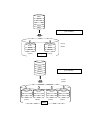
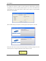
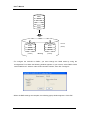
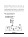
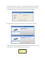
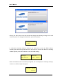
User’s Manual Preface Thank you for purchasing the Samsung DVR storage. This is a user instruction manual for the SVS-5R. The user installing and/or operating this item needs to be aware of this manual and any other manual referenced in this manual before installing or operating and use the item accordingly. This manual, and the software and hardware explained herein are protected by copyright law. All copying, reprinting and translating to other languages of part of or all of its contents without permission of Samsung Techwin Co., Ltd. are not allowed, except for fair use within the scope of copyright law. The specifications of this product are subject to change and upgrade without prior notice. Product Warranty and Limitations The manufacturer of this product is not responsible for any occurrence related to sales of this product, nor does the manufacturer delegate such responsibility to a third party. The product warranty does not cover accidents, negligence, abuse, or improper use for the item in whole or in any part. Additionally, the manufacturer does not provide warranty for any additional part or piece that was not supplied by the manufacturer. The warranty is valid for three years from the purchase date. During this period, the warranty does not cover the malfunctions in the following areas. Malfunction due to user’s Dismantling or replacement by the user Connection to an alternate power source Malfunction due to natural disasters (fire, flood, tsunami, etc.) Replacement due to wear and tear (HDD, Fan, etc.) (The warranty of HDD and Fan is valid for one year from the purchase date.) This warranty specifically excludes product not of Samsung’s manufacture, which may be included as an adjunctive product in any Samsung system. A service charge shall be charged for non-warranty products where the 3-year warranty has expired or voided by customer misuse as described in the cases above. 1 User’s Manual This product is a peripheral device for a security system, not a whole security system protecting against fire and theft. Samsung is not be liable, directly or indirectly, for any loss or damage which is caused by, alleged to be caused by or in connection with the use of the product. Assembly or installation of this item requires experience and technical skills, and unauthorized assembly or installation is strictly prohibited. Unauthorized assembly or installation may cause fire, electric shock, or product malfunction. Please contact your sales agent for help with safe assembly and installation. This manual, and the software and hardware explained herein may differ from your product depending on the version of the firmware and software. The product dimensions and design are subject to change and upgrade without prior notice. 2 User’s Manual Table of Contents CHAPTER 1. SAFETY WARNINGS ................................................. 5 1.1 Warning Symbols ................................................................................................................................5 CHAPTER 2. SUMMARY ................................................................. 8 2.1 Features ..........................................................................................................................................8 2.2 Components ...................................................................................................................................9 2.3 Part Names...................................................................................................................................10 2.3.1 Front I ....................................................................................................................................10 2.3.2 Front II ................................................................................................................................... 11 2.3.3 Back/Rear .............................................................................................................................12 CHAPTER 3. INSTALLATION ........................................................ 13 3.1 Installing HDD ..............................................................................................................................13 3.2 Initializing a HDD .........................................................................................................................15 CHAPTER 4. OPERATION ............................................................ 17 4.1 RAID Settings ...............................................................................................................................17 4.1.1 RAID0 ....................................................................................................................................18 4.1.2 RAID1 ....................................................................................................................................21 4.1.3 RAID0+1................................................................................................................................24 4.1.4 RAID5 ....................................................................................................................................26 4.1.5 RAID5+Hotstandby..............................................................................................................29 4.2 RAID Rebuilding...........................................................................................................................31 4.2.1 RAID0 ....................................................................................................................................31 4.2.2 RAID1 ....................................................................................................................................32 4.2.3 RAID0+1................................................................................................................................33 4.2.4 RAID5 ....................................................................................................................................34 4.2.5 RAID5+Hotstandby..............................................................................................................35 3 User’s Manual CHAPTER 5. CONNECTING TO DVR ........................................... 36 5.1 Adding/Removing a Hard Disk...................................................................................................37 HDD RECOMMENDED MODEL .................................................... 39 SPECIFICATION ............................................................................ 39 PRODUCT DIMENSIONS .............................................................. 40 4 User’s Manual Chapter 1. Safety Warnings 1.1 Warning Symbols Danger Misuse or wrongful operation of the item may result in death, injury, or bring about other harmful results. It indicates absolute caution must be observed when operating said item. Before Setup 9 Please set up the proper voltage (AC 100V~240V) before connecting to a power source. 9 Make sure the power is turned off before set up. 9 There is a risk of shock or fire; be sure to avoid setting up in places with high humidity. 9 To prevent electric or static shocks, connect the ground wire properly. During Use 9 When opening the product cover, there is a risk of electric shock. Only a professional should open the cover. 9 Do not plug in multiple products to a single power source; it is often the cause of short-circuits which may cause fire. 9 Do not place water or any heavy items on top of the product; these may cause a malfunction. 9 Do not use this item in a location containing propane gas, gasoline, or other flammable substances to avoid risk of explosion or fire. 9 Do not touch the power plug with (wet) hands to avoid electric shock. 9 Keep the cooling fan away from any electrical source. 9 Do not pull on the power plug with any force; a damaged plug may cause electric shock or fire. Disassembly and Cleaning 9 There is a risk of malfunction, shock, or other dangers. Do not disassemble or attempt to fix the product yourself. 9 To prevent malfunction or shock, do not use a wet cloth or oil-based cleaning agent to clean the cover of the item. Clean the cover with a dry cloth. User’s Manual Caution Misuse or wrongful operation of the item may result in injury or damage to the item. It indicates caution should be observed when operating. Upon Installation 9 Please keep at least a 15cm distance between the cooling fan and the wall to provide sufficient ventilation. 9 Do not drop or install on an unstable surface to avoid shocks and vibration. These may cause malfunctions. 9 Do not install in areas exposed to direct sunlight or any heat source. Excessive heat may cause deformation and malfunctions. 9 Please avoid installing a new camera while the existing camera is recording. This may decrease the video-quality. To avoid decreasing video quality, please only record after installation of a new camera is complete. During Use 9 Avoid shock and vibration while operating or moving the item. 9 Avoid movement, any impact, or throwing of the item during operation. 9 Before adding hard disks from a third party, please contact your sales agent and avoid a possible malfunction. 9 Using this product in conjunction with hard disks from unauthorized third parties is not covered by the product warranty. 9 This product is a peripheral device for a security system, not a whole security system against fire and theft. Samsung shall not be liable, directly or indirectly, for any loss or damage which is caused by, alleged to be caused by or caused in connection with the use of this item. Samsung Techwin cares for the environment at all stages of product manufacturing to preserve the environment, and is taking a number of steps to provide customers with more environmentally friendly products. The Eco mark represents Samsung Techwin’s wish to create environmentally friendly products, and indicates that the product satisfies the EU RoHS Directive. 6 User’s Manual FCC Compliance Statement Caution : Any changes or modifications in the construction of this device which are not expressly approved by the party responsible for compliance could void the user’s authority to operate the equipment. NOTE : This equipment has been tested, and found to comply with the limitations for a Class A digital device, pursuant to part 15 of the FCC Rules. These limits are designed to provide reasonable protection against harmful interference when the equipment is operated in a commercial environment. This equipment generates, uses, and can radiate radio frequency energy, and if not installed and used in accordance with the instruction manual, may cause harmful interference to radio communications. Operation of this equipment in a residential area is likely to cause harmful interference, in which cause the user will be required to correct the interference at his own expense. Correct Disposal of This Product (Waste Electrical & Electronic Equipment) (Applicable in the European Union and other European countries with separate collection systems) This marking shown on the product or its literature, indicates that it should not be disposed with other household wastes at the end of its working life. To prevent possible harm to the environment or human health from uncontrolled waste disposal, please separate this from other types of wastes and recycle it responsibly to promote the sustainable reuse of material resources. Household users should contact either the retailer where they purchased this product, or their local government office, for details of where and how they can take this item for environmentally safe recycling. Business users should contact their supplier and check the terms and conditions of the purchase contract. This product should not be mixed with other commercial wastes for disposal. User’s Manual Chapter 2. Summary Designed as a 19-inch rack mount unit, this SVS-5R external SATA (eSATA) storage device can be easily mounted in a cabinet along with DVR units. To achieve space efficiency, it is 1U high equipped with slots for a maximum of 4 SATA hard drives. It offers various levels of RAID (Redundant Array of Independent Disks) to provide enhanced data stability and overall system performance. Featuring the hot-swap drive bay option, the SVS-5R enables easy hard drive replacement when errors occur. When configuring the SVS-5R to RAID1, RAID0+1, RAID5, or RAID5+Hotstandby, you can replace SATA hard drives and then rebuild the RAID array when one or more connected SATA hard drives fail. 2.1 Features 1U 19-inch rack case Hardware RAID solution Maximum transfer speed of 3.0Gbps (SATA II) – D1 480fps record and display frame rate Maximum 4 SATA hard drives (250GB~1TB) Supports RAID0, RAID1, RAID0+1, RAID5, and RAID5+Hotstandby Supports hot-swappable hard drive bays Front LCD for the RAID status display Error alarm with sound and light Mute switch for error alarm Supports Plug and Play and Hot Plug Maximized space efficiency and disk capacity at economical costs Expandable for more storage Supported Devices: SVS-3200, SVR-1680, SVR-1645, SVR-960, SVR-945 8 2.2 Components Please make sure that your product includes all of the accessories as shown below. SVS-5R HDD Main Frame (1ea) SATA Cable (1ea) USB Cable (1ea) AC Power Cord (1ea) Screws (1 bag) User’s Manual (1ea) Program CD (1ea) Access Panel Lock (1 pair) Rack Mount Kit (1ea) User’s Manual 2.3 Part Names 2.3.1 Front I ① ② ④ ③ ⑤ Name Function The red LED turns on when the SVS-5R encounters 1 Error LED (Red) 2 Network LED (White) 3 Access Panel Lock Locks or unlocks the front panel of the product. Front LCD Shows the RAID Status of the SVS-5R, status of an error. The white LED turns on when data is being transferred to or from the SVS-5R. connected SATA hard drives, and RAID rebuilding 4 information. 5 Settings Button Performs commands displayed in the front LCD. 10 2.3.2 Front II ① Name 1 Mute Switch 2 Power Switch 3 Power LED (Blue) ② ③ Function Turns off the SVS-5R alarm sound when an error occurs during the RAID operation. Turns the SVS-5R on or off. The blue LED lights up when the SVS-5R is turned on. User’s Manual 2.3.3 Back/Rear ① ② ③ ④ ⑤ Name Function 1 Power Connector 2 Power Fan 3 USB Port Used to set the SVS-5R RAID settings. eSATA Port Used for data transfer to and from the SVS-5R.(DVR 4 5 Connects the power cord to the product. Keeps the SMPS inside the SVS-5R at an optimal temperature. connection port) Cooling FAN Keeps the SVS-5R at an optimal temperature. 12 Chapter 3. Installation 3.1 Installing HDD The SVS-5R supports a maximum of 4 SATA hard drives. To ensure proper installation, please follow the instructions below. ※Caution: All SATA hard drives must be of the same model. - Using the enclosed access panel lock, open the right front panel, and then the left front panel while holding down the two buttons on the left panel. - For the hot-swap drive bays, ① and ③ are shaped identically to each other, while ② and ④ are shaped identically. Please install them in the designated locations. ① ② ③ ④ User’s Manual - Remove a hot-swap drive bay by pulling the handle toward you. - Using the enclosed screws, secure a SATA hard drive to the hot-swap drive bay. 2 screw grooves are located on either side of the hot-swap drive bay. ※Caution: SATA hard drives are of different shape on the front and back. When securing a SATA hard drive to a hot-swap drive bay, please make sure to place the SATA connector on the opposite side of the handle of the drive bay. - Insert the hot-swap drive bay into the back of the main frame. Gently push the drive bay until it reaches the end of the main frame, and then secure it to the frame using the handle. Repeat the procedure to insert SATA hard drives to the other 3 hot-swap drive bays. 14 3.2 Initializing a HDD The SVS-5R shows the status of the RAID operation and connected SATA hard drives through an LCD on the front panel. ※Caution: The SVS-5R is initially set up to “RAID5 4d”. Should connected SATA drive fail, the front LCD indicates the degraded status of the SVS-5R. In this case, you can rebuild the RAID array by replacing the failed SATA hard drive. - Using the enclosed access panel lock, open the right front panel, and then press the power switch on the front panel for at least 2 seconds to turn on the SVS-5R. Power Switch - When the SVS-5R turns on, the front LCD displays a message as shown below. The SVS-5R is initially set up to “RAID5 4d.” To use 4 SATA hard drives for RAID5, please wait for 20 seconds after turning it on. To use a different RAID mode, please refer to 4-1.RAID Settings. User’s Manual ※Caution: The following message appears each time the SVS-5R turns on. To keep the initial RAID settings, please wait 20 seconds after the product is turned on. To change the RAID settings, press the left button to move to the RAID resetting mode. Change RAID mode <-Okay? - If all 4 SATA hard drives are properly connected, the LCD on the front panel displays a message as shown in the window below on the left. To reset the RAID settings, press the left button. If at least one of 4 SATA hard drives fails to connect, the LCD displays a message as shown in the window below on the right. ※Caution: Pressing the left button resets the current RAID settings and deletes entire data saved in the SVS-5R. Please be cautious when using the button except one necessary case: to reset the RAID settings of newly equipped SATA hard drives. RAID5 4d <-Init? -- HALTED -- Cancel-> Bad Disk Count - When the RAID setting of the SVS-5R is reset successfully, the LCD displays a message as shown below. “R5 4d” next to the product name indicates the RAID5 mode is successfully configured for 4 SATA hard drives. “d:OOOO” at the bottom right indicates the status of connected 4 SATA hard drives. The following initials indicate different statuses. e.g.) O: Operating properly F: Failed to connect R: Rebuilding S: on Standby X: Not equipped SVS-5R R5 4d d:OOOO 16 Chapter 4. Operation 4.1 RAID Settings The SVS-5R supports RAID0, RAID1, RAID0+1, RAID5, and RAID5+Hotstandby. ※Caution: The SVS-5R is initially set up to “RAID5 4d”. “RAID5 4d” is to configure 4 SATA hard drives with the RAID5 settings. To use a different RAID mode, please use the ‘Configuration Tool’ in the enclosed CD. - Connect plugs of the enclosed USB cable to the back side of the SVS-5R and a windowsinstalled PC. USB Cable - Press the power switch on the front of the SVS-5R for at least 2 seconds to turn on the SVS5R. Power Switch - When running ‘Configuration Tool’ from the enclosed CD, the following window appears in the computer screen. The following instructions describe how to set up each available RAID mode. ※Caution: Please set up the RAID settings of the SVS-5R before connecting to a DVR to begin saving data. User’s Manual 4.1.1 RAID0 The SVS-5R supports RAID0. Using RAID0 requires 2 or 4 SATA hard drives. When configured to RAID0 with 2 or 4 SATA hard drives, the SVS-5R saves data as shown in the picture below. RAID0 saves data across all connected hard drives and storage; it has the fastest speed and uses the hard drives to full capacity. ※Caution: RAID0 has no fault tolerance; entire data of the SVS-5R is lost if even one SATA hard drive fails. RAID0 is not recommended for saving crucial data. 18 Block1 Block2 Block3 Block4 Block5 Block6 [For 2 HDDs] SVS-5R Block1 Block2 Block3 Block4 Block5 Block6 [HDD#1] Striping (RAID0) [HDD#2] Block1 Block2 Block3 Block4 [For 4 HDDs] Block5 Block6 SVS-5R (RAID0) Block1 Block2 Block3 Block4 Block5 Block6 Block7 Block8 Block9 Block10 Block11 Block12 [HDD#1] [HDD#2] [HDD#3] Striping [HDD#4] User’s Manual - To configure the SVS-5R to RAID0, you must change the RAID mode by using the Configuration Tool. When the following window appears on your screen, select RAID0 under “Select RAID level”. Under “Select number of disks”, select a number of connected SATA hard drives. Click “Configure”. - When the RAID settings are complete, the following popup window appears. Click “Exit”. - Clicking the “Exit” button resets the SVS-5R and displays the following message on the LCD at the front panel. To change the RAID mode, click the button on the left. Change RAID mode <-Okay? 20 - A confirmation message appears, asking if you really want to reset the RAID settings. Resetting the RAID settings will delete the entire data saved in the SVS-5R. When the following window appears, press the left button to reset the RAID settings. Warning!!! RAID0 4d Data can be lost <-Init? Cancel-> - When the RAID0 mode is successfully configured, the LCD at the front will display the following message. Connect to a DVR to begin saving data. SVS-5R R0 4d d:OOOO 4.1.2 RAID1 SVS-5R supports the RAID1. Using RAID1 requires 2 SATA hard drives; HDD#3 and HDD#4 are not used. When configured to RAID1, the SVS-5R saves data as shown in the picture below. In the RAID1 mode, each of the two hard drives stores identical data. Thus, data is not lost even if either SATA hard drive fails. When a SATA hard drive fails, the SVS-5R continues saving data to the other hard drive. To ensure data stability however, it is highly recommended that you replace the failed hard drive and rebuild the RAID array. In the RAID1 mode, total storage capacity of the SVS-5R is simply the capacity of one drive; please check total storage capacity of the SVS-5R before configuring it to RAID1. User’s Manual Block1 Block2 Block3 Block4 Block5 Block6 SVS-5R Block1 Block1 Block2 Block2 Block3 Block3 [HDD#1] (RAID1) [HDD#2] Mirroring - To configure the SVS-5R to RAID1, you must change the RAID mode by using the Configuration Tool. When the following window appears on your screen, select RAID1 under “Select RAID level”. Select 2 under “Select number of disks”, then click “Configure”. - When the RAID settings are complete, the following popup window appears. Click “Exit”. 22 - Clicking the “Exit” button resets the SVS-5R and displays the following message on the LCD at the front panel. To change the RAID mode, press the left button. Change RAID mode <-Okay? - A confirmation message appears asking if you really want to reset the RAID settings. Resetting the RAID settings deletes ALL data saved in the SVS-5R. When the following window appears, press the left button to reset the RAID settings. Warning!!! RAID1 2d Data can be lost <-Init? Cancel-> - When the RAID1 mode is successfully configured the front LCD displays the following message. Connect to a DVR to begin saving data. SVS-5R R1 2d d:OOXX User’s Manual 4.1.3 RAID0+1 The SVS-5R supports RAID0+1. Using RAID0+1 requires 4 SATA hard drives. When configured to RAID0+1, the SVS-5R saves data as shown in the picture below. RAID0+1 uses both striping (RAID0) and mirroring (RAID1); it will store identical data to 2 RAID0 disk arrays. Thus, data is not lost even if a SATA hard drive or either disk array should fail. When a SATA hard drive or a disk array fails, the SVS-5R continues saving data to the other RAID0 disk array. To ensure data stability, however, it is highly recommended that you replace a failed hard drive and rebuild the RAID array. In the RAID0+1 mode, total storage capacity of the SVS-5R is simply the capacity of 2 drives; please check total storage capacity of the SVS-5R before configuring it to RAID0+1. The following describes possible instances when 2 SATA hard drives simultaneously fail during the RAID0+1 mode. e.g.) HDD#1, HDD#2 fail Æ Rebuilding Can be rebuilt HDD#1, HDD#3 fail Æ Halt, Entire data is lost HDD#1, HDD#4 fail Æ Can be rebuilt HDD#2, HDD#3 fail Æ Can be rebuilt HDD#2, HDD#4 fail Æ Halt, Entire data is lost HDD#3, HDD#4 fail Æ Can be rebuilt Block1 Block2 Block3 Block4 Block5 Block6 SVS-5R (RAID0+1) Mirroring Block1 Block2 Block1 Block2 Block3 Block4 Block3 Block4 Block5 Block6 Block5 Block6 [HDD#1] [HDD#2] [HDD#3] Striping [HDD#4] Striping 24 - To configure the SVS-5R to RAID0+1, you must change the RAID mode by using the Configuration Tool. When the following window appears in the screen, select RAID0+1 under “Select RAID level”. Select 4 under “Select number of disks”, then click “Configure”. - When the RAID settings are complete, the following popup window appears. Click “Exit”. - Clicking the “Exit” button resets the SVS-5R and displays the following message on the LCD at the front panel. To change the RAID mode, press the left button. Change RAID mode <-Okay? User’s Manual - A confirmation message appears asking you if you really want to reset the RAID settings. Resetting the RAID settings will delete ALL saved in the SVS-5R. When the following window appears, press the left button to reset the RAID settings. Warning!!! RAID0+1 4d Data can be lost <-Init? Cancel-> - When the RAID0+1 mode is successfully configured, the LCD will display the following message. Connect to a DVR to begin saving data. SVS-5R R0+1 4d d:OOOO 4.1.4 RAID5 The SVS-5R supports RAID5. Using RAID5 requires 3 or 4 SATA hard drives. When configured to RAID5, the SVS-5R saves data as shown in the picture below. RAID5 uses block-level striping with parity data to save data across all connected SATA hard drives. Thus, data is not lost even if a hard drive fails. When a SATA hard drive fails, the SVS-5R continues saving data to the remaining hard drives. To ensure data stability however, it is highly recommended that you replace a failed hard drive and rebuild the RAID array. In the RAID5 mode, total storage capacity of the SVS-5R is the capacity of total SATA hard drives subtracted by one drive. Although RAID5 has decreased data storage capacity, it is most recommended as it is safest and has larger capacity than RAID0+1. 26 Block1 Block2 Block3 Block4 Block5 Block6 SVS-5R (RAID5) Block1 Block2 Block3 Parity(1,2,3) Block4 Block5 Parity(4,5,6) Block6 Block7 Parity(7,8,9) Block8 Block9 [HDD#1] [HDD#2] [HDD#3] [HDD#4] - To configure the SVS-5R to RAID5, you must change the RAID mode by using the Configuration Tool. When the following window appears on your screen, select RAID5 under “Select RAID level”. Under “Select number of disks”, select a number of connected SATA hard drives and click “Configure”. - When the RAID settings are complete, the following popup window appears. Click “Exit”. User’s Manual - Clicking the “Exit” button resets the SVS-5R and displays the following message on the LCD at the front panel. To change the RAID mode, press the left button. Change RAID mode <-Okay? - A confirmation message appears, asking if you really want to reset the RAID settings. Resetting the RAID settings will delete ALL data saved in the SVS-5R. When the following window appears, press the left button to reset the RAID settings. Warning!!! RAID5 4d Data can be lost <-Init? Cancel-> - When the RAID5 mode is successfully configured, the LCD displays the following message. Connect to a DVR to begin saving data. SVS-5R R5 4d d:OOOO 28 4.1.5 RAID5+Hotstandby SVS-5R supports RAID5+Hotstandby. Using RAID5+Hotstandby requires 4 SATA hard drives. When configured to RAID5+Hotstandby, the SVS-5R saves data as shown in the picture below. RAID5+Hotstandby uses 3 SATA hard drives in the RAID5 mode, while putting on the last drive on standby. ※Caution: In the RAID5+Hotstandby mode, HDD#4 in the SVS-5R is put on standby. When a SATA hard drive in the RAID5 mode fails, the standby drive replaces the failed drive to rebuild the RAID array and allow the SVS-5R to continue saving data. To ensure data stability however, it is highly recommended that you replace the failed hard drive immediately. In the RAID5+Hotstandby mode, total storage capacity of the SVS-5R is simply the capacity of 2 drives. It is more stable than RAID5, but has decreased storage capacity; please consider the storage capacity before using this mode. Block1 Block2 Block3 Block4 Block5 Block6 SVS-5R (RAID5+Hotstandby) Block1 Block2 Parity(1,2) Block3 Parity(3,4) Block4 Parity(5,6) Block5 Block6 [HDD#1] [HDD#2] [HDD#3] Standby [HDD#4] User’s Manual - To configure the SVS-5R to RAID5+Hotstandby, you must change the RAID mode by using the Configuration Tool. When the following window appears in the screen, select RAID5 under “Select RAID level”. Select 3+Hotstandby under “Select number of disks”, then click “Configure”. - When the RAID settings are complete, the following popup window appears. Click “Exit”. - Clicking the “Exit” button resets the SVS-5R and displays the following message on the LCD at the front panel. To change the RAID mode, press the left button. Change RAID mode <-Okay? 30 - A confirmation message appears asking you if you really want to reset the RAID settings. Resetting the RAID settings will delete ALL data saved in the SVS-5R. When the following window appears, press the left button to reset the RAID settings. Warning!!! RAID5 3d+HS Data can be lost <-Init? Cancel-> - When the RAID5+Hotstandby mode is successfully configured, the LCD displays the following message. Connect to a DVR to begin saving data. SVS-5R R5 3d d:OOOS 4.2 RAID Rebuilding When the SVS-5R is in the RAID rebuilding process and its connected DVR is in the Half D1 or D1 mode, activating the playback option may cause skipping frames. This skipping frame issue is simply caused by the RAID rebuilding process; once it is complete, the screen will no longer skip frames and no data is damaged. 4.2.1 RAID0 In the RAID0 mode, ALL data saved in the SVS-5R is lost if only ONE of the connected SATA hard drives fails. ※Caution: RAID0 does not offer the rebuilding option; you must replace a failed hard drive and reinitialize a RAID mode. - During the RAID0 mode when one of connected SATA hard drives fails, the front LCD of the SVS-5R displays the following message notifying you of the loss of ALL data. -- HALTED -Bad Disk Count User’s Manual ※Caution: RAID0 is not recommended for saving crucial data. 4.2.2 RAID1 During the RAID1 mode, when a SATA hard drive fails, replace it and then rebuild the RAID array. - During the RAID1 mode, when a SATA hard drive fails, the SVS-5R activates a beeping sound, as well as the RAID error LED. To disable the beeping sound, open the front panel using the access panel lock, and then press the front mute switch. The front LCD will display the SVS-5R status as Degraded. d:FOXX; indicating a failed SATA hard drive. Degraded R1 2d d:FOXX - When a failed SATA hard drive is replaced with a new one, the LCD displays the following message. Press the left button to start rebuilding the RAID array. RAID rebuilding? <-Okay? - During the rebuilding process, the front LCD displays the following message. This indicates a rebuilding SATA hard drive and the remaining time. Rebuild d:ROXX 1h:31m - When the RAID array is successfully rebuilt, the front LCD displays the following message. SVS-5R R1 2d d:OOXX 32 4.2.3 RAID0+1 During the RAID0+1 mode, when a SATA hard drive fails, replace it and then rebuild the RAID array. - During the RAID0+1 mode, when a SATA hard drive fails, the SVS-5R activates beeping sounds and the RAID error LED. To disable the beeping sounds, open the front panel using the access panel lock, and then press the mute switch. The front LCD will display the SVS-5R status as Degraded. d:FOOO; indicating a failed SATA hard drive. Degraded R0+1 4d d:FOOO - When the failed SATA hard drive is replaced with a new one, the LCD displays the following message. Press the left button to start rebuilding the RAID array. RAID rebuilding? <-Okay? - During the rebuilding process, the front LCD displays the following message. It indicates a rebuilding SATA hard drive, and the time remaining until completion. Rebuild d:ROOO 1h:31m - When the RAID array is successfully rebuilt, the front LCD displays the following message. SVS-5R R0+1 4d d:OOOO User’s Manual 4.2.4 RAID5 During the RAID5 mode, when a SATA hard drive fails, replace it and then rebuild the RAID array. - During the RAID1 mode, when a SATA hard drive fails, the SVS-5R activates beeping sounds and the RAID error LED. To disable the beeping sounds, open the front panel using the access panel lock, and then press the mute switch. The front LCD will display the SVS-5R status as Degraded. d:FOOO indicates a failed SATA hard drive. Degraded R5 4d d:FOOO - When the failed SATA hard drive is replaced with a new one, the LCD displays the following message. Press the left button to start rebuilding the RAID array. RAID rebuilding? <-Okay? - During the rebuilding process, the front LCD displays the following message to indicate a SATA hard drive rebuilding, and the time remaining until completion. Rebuild d:ROOO 1h:31m - When the RAID array is successfully rebuilt, the front LCD displays the following message. SVS-5R R5 4d d:OOOO 34 4.2.5 RAID5+Hotstandby During the RAID5+Hotstandby mode, when a SATA hard drive fails, another hard drive in standby replaces the failed drive and rebuilds the RAID array. When replacing the failed SATA hard drive, the new hard drive is automatically set to standby status. - During the RAID5+Hotstandby mode, when a SATA hard drive fails, the SVS-5R activates beeping sounds and the RAID error LED. To disable the beeping sounds, open the front panel using the access panel lock, and then press the front mute switch. Check the front LCD to make sure that the standby SATA hard drive has replaced the failed drive and begun rebuilding the RAID array automatically. d:FOOR indicates both the failed SATA hard drive and rebuilding one as well as the time to remaining rebuild the RAID array. Rebuild d:FOOR SVS-5R 1h:31m R5 3d d:OOOS - When the failed SATA hard drive is replaced with a new one, the LCD displays the following message. To put the new hard drive on standby, press the left button. RAID rebuilding? <-Okay? - The new hard drive is in standby mode while the RAID is being rebuilt. Rebuild d:SOOR 1h:31m - When the RAID array is successfully rebuilt, the front LCD displays the following message. SVS-5R R5 3d d:SOOO User’s Manual Chapter 5. Connecting to DVR The SVS-5R HDD extension unit uses the eSATA port to connect to a DVR. To ensure proper installation, please follow the instructions below. ※ Applicable Models: SVR-3200, SVR-1680, SVR-1645, SVR-960, SVR-945 - Please check the eSATA port on the back side of the SVS-5R. eSATA Port - Connect plugs of the enclosed eSATA cable to the eSATA port of a DVR and the SVS-5R. ※Caution: Please use the enclosed eSATA cable to connect the SVS-5R to a DVR. 36 5.1 Adding/Removing a Hard Disk This section describes how to add, remove or format a hard disk. Select “System Setup/Disk” in the menu. Disk Manager Disk Manager is used to manage internal and external HDDs. It manages HDD status, bad blocks, disk size, enabled/disabled status, etc. User’s Manual Type : Displays disk locations and types. Int A (Internal A HDD), Int B (Internal B HDD), Ext (External HDD) Model : Displays HDD models. Bad Block : Displays HDDs with bad blocks. 0 is displayed when there are no problems. Nothing is displayed for HDDs not in use. Size( in MB) : Displays HDD sizes in MB. Enabled (Yes/No) : Enables or disables HDDs. Yes: Enabled / No: Disabled To Change HDD to Yes - Enabled: While selecting No, press the [Enter] button or use the mouse wheel to open the notice window, which shows the following message: - “Warning: This disk is usable without being formatted. Do you want to format the disk anyway?” - - Select No to keep the previous data stored in the HDD and change it to Enabled-Yes. - Select Yes to delete the previous data stored in the HDD and change it to Enabled-Yes. To change HDD to No - Enabled: While selecting Yes, press the [Enter] button or use the mouse wheel to open the notice window to display the following message: - “Warning: Do you want to remove the disk?” - Select Yes to open the “The disk has been removed.” message and change the HDD to Enabled-No. - The HDD is now unused. ※Caution: The SVS-5R does not offer you to save data selectively to a hard drive; it automatically starts saving data starting from a last-enabled HDD. 38 HDD Recommended Model Seagate Technology Western Digital Size Model Size Model 1,000GB ST31000340SV 1,000GB WD10EVCS 750GB ST3750840SCE 750GB WD7500AVCS 500GB ST3500830SCE 500GB WD5000AVJS 250GB ST3250820SCE 250GB WD2500AVJS Specification SVS-5R Transmission Speed Maximum Capacity Internal HDD RAID eSATA Up to 3.0Gbps (SATA II) Up to 4TB Up to 4 SATA HDDs (Support Hot-Swap Function) RAID 0,1,0+1,5 1 External SATA ports for DVR connection USB USB2.0, RAID configuration only Operating Temperature +5°C ~ +45°C (+41°F ~ +113°F) Operating Humidity Input Voltage 20%RH ~ 70%RH 115~230V AC ±10%, 50/60 Hz, Autoranging Dimensions (W×H×D) 482ⅹ44×433mm (18.97"×1.73"×17.04") Weight(4X hard disks) Approx. 6.4Kg (14.1 lb) Rack Mount Kit Supported Devices Certifications For mounting one unit in an EIA 19-inch rack SVR-3200/1680/1645/960/945 FCC (Class A), UL/cUL listed, CE (Class A) User’s Manual Product Dimensions 40