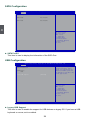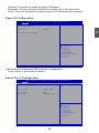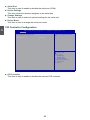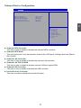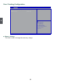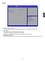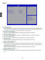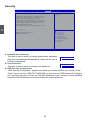
1
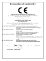
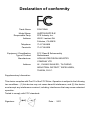
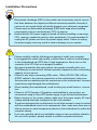
AHD1S Series
Motherboard
User’s Manual
Statement:
This manual is the intellectual property of Foxconn, Inc. Although the information
in this manual may be changed or modified at any time, Foxconn does not obligate
itself to inform the user of these changes.
Trademark:
All trademarks are the property of their respective owners.
Version:
User’s Manual V1.0 for AHD1S Series motherboard.
CA
UT
IO
N
Symbol description:
!
NING
AR
!
W
Caution : refers to important information that can help you to use motherboard
better, and tells you how to avoid problems.
Warning : indicating a potential risk of hardware damage or physical injury may
exist.
WEEE:
The use of this symbol indicates that this product may not be treated as household
waste. By ensuring this product is disposed of correctly, you will help prevent potential
negative consequences for the environment and human health, which could otherwise
be caused by inappropriate waste handling of this product. For more detailed
information about recycling of this product, please contact your local city office, your
household waste disposal service or the shop where you purchased this product.
More information:
If you want more information about our products, please visit Foxconn’s
website: http://www.foxconnchannel.com
© All rights reserved.
All trade names are registered trademarks of respective manufacturers listed.
All images are for reference only, please refer to the physical motherboard for specific features.
Declaration of conformity
HON HAI PRECISION INDUSTRY COMPANY LTD
66 , CHUNG SHAN RD., TU-CHENG INDUSTRIAL DISTRICT,
TAIPEI HSIEN, TAIWAN, R.O.C.
declares that the product
Motherboard AHD1S/AHD1S-K
is in conformity with
(reference to the specification under which conformity is declared in
accordance with 89/336 EEC-EMC Directive)
■ EN 55022:1998/A2: 2003 Limits and methods of measurements of radio disturbance characteristics of information technology equipment
■ EN 61000-3-2/:2000 Electromagnetic compatibility (EMC)
Part 3: Limits
Section 2: Limits for harmonic current emissions
(equipment input current <= 16A per phase)
■ EN 61000-3-3/A1:2001 Electromagnetic compatibility (EMC)
Part 3: Limits
Section 2: Limits of voltage fluctuations and flicker in low voltage supply systems for equipment with rated current <= 16A
■ EN 55024/A2:2003 Information technology equipment-Immunity characteristics limits and methods of measurement
Signature : Printed Name : James Liang Place / Date : TAIPEI/2011
Declaration of conformity
Trade Name:
FOXCONN
Model Name:
Responsible Party:
Address:
Telephone:
Facsimile:
AHD1S/AHD1S-K
Equipment Classification:
Type of Product:
Manufacturer:
Address:
FCC Class B Subassembly
Motherboard
HON HAI PRECISION INDUSTRY
COMPANY LTD
66 , CHUNG SHAN RD., TU-CHENG
INDUSTRIAL DISTRICT, TAIPEI HSIEN, TAIWAN, R.O.C.
PCE Industry Inc.
458 E. Lambert Rd.
Fullerton, CA 92835
714-738-8868
714-738-8838
Supplementary Information:
This device complies with Part 15 of the FCC Rules. Operation is subject to the following
two conditions : (1) this device may not cause harmful interference, and (2) this device
must accept any interference received, including interference that may cause undesired
operation.
Tested to comply with FCC standards.
Signature : Date :
2011
Installation Precautions
NING
AR
!
W
■
CA
UT
IO
N
■
!
■
■
■
■
■
■
■
■
Electrostatic discharge (ESD) is the sudden and momentary electric current
that flows between two objects at different electrical potentials. Normally it
comes out as a spark which will quickly damage your electronic equipment.
Please wear an electrostatic discharge (ESD) wrist strap when handling
components such as a motherboard, CPU or memory.
Ensure that the DC power supply is turned off before installing or removing
CPU, memory, expansion cards or other peripherals. It is recommended to
unplug the AC power cord from the power supply outlet. Failure to unplug
the power supply cord may result in serious damage to your system.
Please carefully read the following procedures to install your computer :
It is suggested to select high-quality, certified fans in order to avoid damage
to the motherboard and CPU due to high temperature. Never turn on the
computer if the CPU fan is not properly installed.
We cannot guarantee that your system can operate normally when your
CPU/Memory is overclocked. Normal operation depends on the overclocking
capacity of your device.
If there is any, when connecting USB, audio, 1394a, RS232 COM, IrDA or
S/PDIF cables to the internal connectors on the motherboard, make sure
their pinouts are matching with the connectors on the motherboard. Incorrect
connections might damage the motherboard.
When handling the motherboard, avoid touching any metal leads or connectors.
If there is a PCI Express x16 graphics card installed in your system, we
recommend using a 24-pin ATX power supply to get the best performance.
Before turning on the power, please make sure the power supply AC input
voltage setting has been configured to the local standard.
To prevent damage to the motherboard, do not allow screws to come in contact
with the motherboard circuit or its components. Also, make sure there are no
leftover screws or metal components placed on the motherboard or within the
computer casing.
If you are uncertain about any installation steps or have a problem related to
the use of the product, please consult a certified computer technician.
Table of Contents
Chapter 1 Product Introduction
Product Specifications................................................................... 2
Layout............................................................................................ 4
Back Panel Connectors................................................................. 5
Chapter 2 Installation
Install the Memory......................................................................... 8
Install an Expansion Card............................................................. 9
Install other Internal Connectors................................................. 10
Jumpers....................................................................................... 14
Install Driver and Utility................................................................ 15
Chapter 3 BIOS Setup
Enter BIOS Setup........................................................................ 19
Main............................................................................................. 20
Advanced.................................................................................... 22
Chipset........................................................................................ 29
Boot............................................................................................. 31
Power.......................................................................................... 32
Health.......................................................................................... 33
Security ...................................................................................... 34
Save & Exit . ............................................................................... 36
Technical Support :
Support
Website :
http://www.foxconnchannel.com
Support Website :
http://www.foxconnsupport.com
Worldwide online contact Support :
http://www.foxconnsupport.com/inquiry.aspx
CPU Support List :
http://www.foxconnsupport.com/cpusupportlist.aspx
Memory, VGA Compatibility List :
http://www.foxconnsupport.com/complist.aspx
Thank you for buying Foxconn AHD1S Series motherboard. Foxconn
products are engineered to maximize computing power, providing only
what you need for break-through performance.
With advanced overclocking capability and a range of connectivity
features for today multi-media computing requirements, AHD1S/
AHD1S-K enables you to unleash more power from your computer.
This chapter includes the following information:
■
Product Specifications
■
Layout
■
Back Panel Connectors
1
1-1 Product Specifications
CPU
Zacate Dual Core APU, Max processor power up to 18W
For the latest CPU information, please visit:
http://www.foxconnsupport.com/cpusupportlist.aspx
Chipset
Hudson D1
Memory
2 x 240-pin DDR3 DIMMs
Support up to 8GB of system memory
Dual Channel DDR3 1066MHz architecture
Expansion Slots
1 x PCI Express x16 slot (only support PCIE x 4 card )
VGA
AMD Radeon HD 6310 Graphics
support Direct X11 compliant
Storage
Hudson D1 chipset:
- 2 x SATA 2.0 connectors 300MB/s data transfer rate
- Support hot plug and NCQ (Native Command Queuing )
LAN
Realtek RTL8111E Gigabit LAN chip
(co-lay Realtek RTL8105E 10/100Mb/s LAN chip)
Audio
Realtek ALC662 audio chip:
- High Definition Audio
- 2/4/5.1-channel
- Support for S/PDIF Out
- Support Jack-Sensing function
USB
Hudson D1 chipset:
- Support up to 10 x USB 2.0 ports (6 rear panel ports, 2 onboard USB
headers supporting 4 extra ports)
Internal Connectors
1 x 24-pin ATX main power connector
1 x 4-pin ATX 12V power connector
2 x SATA 2.0 connectors
2 x USB 2.0 connectors (supporting 4 x USB devices)
1 x CPU fan header (4-pin)
1 x System fan header (4-pin)
1 x Front panel connector
1 x Front Audio connector
1 x S/PDIF_OUT connector
1 x Speaker connector
1 x Chassis intrusion alarm header
1 x COM connector
1 x TPM connector
1 x CIR connector
(Continued on the next page)
1 x PS/2 Keyboard port
1 x VGA port
1 x DVI-D port
1 x HDMI port
6 x USB 2.0 ports
1 x RJ-45 LAN port
6-channel Audio ports
Hardware Monitor
System voltage detection
CPU/System temperature detection
CPU/System fan speed detection
CPU overheating warning
CPU/System fan speed control
PCI Express x16
Transfer rate per lane are 2.5GT/s for PCIe Gen 1 and 5GT/s for PCIe
Gen 2. Low power consumption and power management features
Green Function
Support ACPI (Advanced Configuration and Power Interface)
Support S0 (normal), S1 (power on suspend), S3 (suspend to RAM),
S4 (suspend to disk), S5 (soft - off)
Support EuP function
Bundled Software
FOX ONE
FOX LiveUpdate
FOX LOGO
FOX DMI
Operating System
Support for Microsoft® Windows® 7/Vista/XP
Form Factor
Mini-ITX Form Factor, 6.7 inches x 6.7inches (17cm x17cm)
1
Back Panel
Connectors
1-2 Layout
1
7
6
5
4
3
2
1
8
18
17
9
16
15
14
10
11
13
12
1. COM Connector
2. TPM Connector
3. Clear CMOS Jumper
4. Front USB Connectors
5. Front Audio Connector
6. System Fan Header
7. SPDIF_OUT Connector
8. Chassis Intrusion Alarm Header
9. PCI Express x16 Slot
10. Front Panel Connector
11. CIR Connector
12. 24-pin ATX Power Connector
13. Speaker Connector
14. DDR3 DIMM Slots
15. SATA Connectors
16. Zacate Dual Core APU
17. Chipset: Hudson D1
18. 4-pin ATX 12V Power Connector
Note : The above motherboard layout is for reference only, please refer to the physical
motherboard for detail.
1-3 Back Panel Connectors
VGA Port
LAN Port
3
1
1
PS/2 Keyboard
Port
6
Line In
Line Out
Microphone In
2
USB Ports
2
4
5
DVI-D Port
HDMI Port
7
USB Ports
Audio Ports
1. PS/2 Keyboard Port
Use the lower port (purple) to connect a PS/2 keyboard.
2. USB Ports
The USB port supports the USB 2.0/1.1 specification. Use this port for USB devices such as an
USB keyboard/mouse, USB printer, USB flash drive and etc.
3. VGA Port
To connect with external display devices, such as monitor or LCD display.
4. DVI-D Port
The DVI-D port supports DVI-D specification. Connect a monitor that supports DVI-D connection
to this port.
5. HDMI Port
The HDMI (High-Definition Multimedia Interface) provides an all-digital audio/video interface to
transmit the uncompressed audio/video signals and is HDCP compliant. Connect the HDMI audio/
video device to this port. The HDMI Technology can support a maximum resolution of 1920x1080p
but the actual resolutions supported depend on the monitor being used.
6. RJ-45 LAN Port
The Ethernet LAN port provides Internet connection at up to 10/100/1000Mb/s data rate.
LAN Type
1000M
Left: Active
Right: Link
Status
Description
Status
Off
No Link
Off
No Link
Off
10Mb/s Connection
Green
Blinking
Data Activity
Description
Green
100Mb/s Connection
Orange
1000Mb/s Connection
Active
LED
Link
LED
1
7. Audio Ports
For the definition of each audio port, please refer to the table below :
Port
2-channel
4-channel
5.1-channel
Blue
Line In
Rear Speaker Out
Rear Speaker Out
Green
Line Out
Front Speaker Out
Front Speaker Out
Pink
Microphone In
Microphone In
Center/Subwoofer
Speaker Out
* : Please refer to Chapter 4, and install the Realtek audio driver (in CD) to assign the audio
output ports for different applications of 2/4/5.1 channels. The fundamental audio outputs are
depicted in the table above.
This chapter introduces the hardware and software installation process, including the installation of the CPU, memory, power supply,
slots, pin headers and the mounting of jumpers. Caution should be
exercised during the installation of these modules. Please refer to the
motherboard layout prior to any installation and read the contents in
this chapter carefully.
This chapter includes the following information :
■
Install the Memory
■
■
■
Install other Internal Connectors
Jumpers
Install Driver and Utility
Please visit the following website for more supporting information about your motherboard.
CPU Support List:
http://www.foxconnsupport.com/cpusupportlist.aspx
Memory, VGA Compatibility List:
http://www.foxconnsupport.com/complist.aspx
CA
UT
IO
N
2-1 Install the Memory
!
■
■
144-Pin
■
Read the following guidelines before you begin to install the memory :
Make sure that the motherboard supports the memory. It is recommended that memory
of the same capacity, brand, speed, and chips be used.
Always turn off the computer and unplug the power cord from the power outlet before
installing the memory to prevent hardware damage.
Memory modules have a foolproof design. A memory module can be installed in only
one direction. If you are unable to insert the memory, switch the direction.
Be sure to install DDR3 DIMMs on this motherboard.
Notch
96-Pin
2
■
If you take a look at front side of memory module, it has asymmetric pin counts on both sides
separated by a notch in the middle, so it can only fit in one direction. Follow the steps below to
correctly install your memory modules into the sockets.
Step 1:
Spread the clips at both ends of the memory socket.
Place the memory module onto the socket, then put
your fingers on top edge of the module, and push it
down firmly and seat it vertically into the memory
socket.
Step 2:
The clips at both ends of the socket will snap into
place when the memory module is securely inserted.
CA
UT
IO
N
2-2 Install an Expansion Card
!
PCI Express x16
Follow the steps below to correctly install your expansion card in the expansion slot.
1. Locate an expansion slot that supports your card. Remove the metal slot cover from the chassis
back panel.
2. Align the card with the slot, and press down on the card until it is fully seated in the slot.
3. Make sure the metal contacts on the card are completely inserted into the slot.
4. Secure the card's metal bracket to the chassis back panel with a screw.
5. After installing all expansion cards, replace the chassis cover.
6. Turn on your computer. If necessary, go to BIOS Setup to make any required BIOS changes for
your expansion card(s).
7. Install the driver provided with the expansion card in your operating system.
Installing and Removing a PCI Express x16 Graphics Card :
• Installing a Graphics Card:
Gently insert the graphics card into the PCI Express x16 slot. Make
sure the graphics card is locked by the latch at the end of the PCI
Express x16 slot.
• Removing the Card:
Push the latch at the end of the PCI Express x16 slot to release
the card and then pull the card straight up from the slot.
2
■ Make sure the motherboard supports the expansion card. Carefully read the manual
that came with your expansion card.
■
Always turn off the computer and unplug the power cord from the power outlet before
installing an expansion card to prevent hardware damage.
2-3 Install other Internal Connectors
Power Connectors
24-pin ATX power connector : PWR2
PWR2 is the ATX power supply connector. Make sure that the power supply cable and pins are
properly aligned with the connector on the motherboard. Firmly plug the power supply cable into the
connector and make sure it is secure.
13
24
12
CA
UT
IO
N
2
This motherboard uses an ATX power supply. In order not to damage any device, make sure all the
devices have been installed properly before applying the power supply.
!
Pin #
Definition
Pin #
Definition
1
3.3V
13
3.3V
2
3.3V
14
-12V
3
GND
15
GND
4
+5V
16
PS_ON(Soft On/Off)
5
GND
17
GND
6
+5V
18
GND
7
GND
19
GND
8
Power Good
20
NC
9
+5V SB(Stand by +5V)
21
+5V
10
+12V
22
+5V
11
+12V
23
+5V
12
3.3V
24
GND
1
PWR2
Pin No. 24
We recommend you using a 24-pin power supply.
If you are using a 20-pin power supply, you need
to align the ATX power connector according to
the picture.
20-Pin Power
4-pin ATX 12 V Power Connector : PWR1
Connect the 4-pin ATX 12V power supply to PWR1 and provides power to the CPU.
3
1
+12V
GND
4
2
PWR1
10
Pin #
Definition
1
GND
2
GND
3
+12V
4
+12V
1
2
+5V
EMPTY
SPDIF_OUT
GND
S/PDIF OUT Connector : SPDIF_OUT1
The connector is used for S/PDIF output.
3
4
SPDIF_OUT1
USB Connectors : F_USB1/2
2
2
1
VCC
DD+
GND
EMPTY
VCC
DD+
GND
GND
9 10
F_USB 1/2
In addition to the four USB ports on the rear panel, this
product also provides two 10-pin USB headers on its
motherboard. By connecting through USB cables with
them, user can quickly expand another four USB ports
on the front panel.
TPM Connector : TPM1
The TPM (Trusted Platform Module) provides the ability
to the PC to run applications more secure and to make
transactions and communication more trustworthy. To
utilize this function, you should purchase additional
device and install it.
1 2
LCLK#
GND
LFRAME#
EMPTY
LRESET#
LAD3
NC
LAD2
VDD
LAD1
LAD0
NC
SB3V
GND
GND
NC
SERIRQ
CLKRUN#
LPCPD#
NC
19 20
TPM1
COM Connector : COM1
This motherboard supports one serial RS232 COM port
for legacy compatibility. User must purchase another
RS232 cable with a 9-pin D-sub connector at one end
to connect with the external RS232 device and another
end with 10-pin female connector to connect with COM1
connector in the motherboard.
1
2
RLSD
SIN
SOUT
DTR
GND
DSR
RTS
CTS
EMPTY
RI
9 10
COM1
11
IrDA Connector : CIR
This connector supports infrared wireless transmitting and
receiving device.
1 2
+5VSB
CIRRX
GND
CIRTX
+5V
EMPTY
NC
GND
NC
EMPTY
2
9 10
CIR
Front Panel Connector : FP1
This motherboard includes one connector for connecting the
front panel switch and LED Indicators.
Hard Disk LED Connector (HDD-LED)
Connect to the chassis front panel IDE indicator LED. It
indicates the active status of the hard disks. This 2-pin
connector is directional with +/- sign.
Reset Switch (RESET-SW)
Attach the connector to the Reset switch on the front
panel of the case; the system will restart when the switch
is pressed.
Power LED Connector (PWR-LED)
Connect to the power LED indicator on the front panel of
the chassis. The Power LED indicates the system’s status.
When the system is in operation (S0 status), the LED is
on. When the system gets into sleep mode (S1) , the LED
is blinking; When the system is in S3/S4 sleep state or
power off mode (S5), the LED is off. This 2-pin connector
is directional with +/- sign.
HDD-LED
+
1
2
-
+
PWR-LED
-
RESET-SW
PWR-SW
NC
Power Switch Connector (PWR-SW)
Connect to the power button on the front panel of the
chassis. Push this switch allows the system to be turned
on and off rather than using the power supply button.
EMPTY
9 10
FP1
1
GND
TX+
TXGND
RXRX+
GND
Serial ATA Connectors : SATA_1/2
The Serial ATA connector is used to connect with SATA Hard
Disk or CD devices which supporting this feature. The current
Serial ATA II interface allows up to 300MB/s data transfer
rate.
SATA _1/2
12
Audio Connector : F_AUDIO1
The audio connector supports HD Audio standard.
It provides the Front Audio output choice.
A_MIC2_L
A_MIC2_R
A_LINE2_R
SENSE_SEND
A_LINE2_L
1 2
9 10
AUD_GND
PRESENCEJ
SENSE1_RETURN
EMPTY
SENSE2_RETURN
Fan Headers : CPU_FAN1, SYS_FAN1
1
There are two main fan headers on this motherboard. The fan
speed can be controlled and monitored in “PC Health Status”
section of the BIOS Setup. These fans can be automatically
turned off after the system enters S3, S4 and S5 sleeping
states.
2
F_AUDIO1
GND
POWER
SENSE
CONTROL
CPU_FAN1/SYS_FAN1
Chassis Intrusion Alarm Header : C_INTRUSION1
The connector can be connected to a security switch on the
chassis. The system can detect the chassis intrusion through
the function of this connector. If eventually the chassis is
closed, the system will send a message out.
INTRUDERJ
1
GND
C_INTRUSION1
Speaker Connector : SPEAKER1
The speaker connector is used to connect speaker of the
chassis.
PWR
EMPTY
NC
SPKJ
1
2
3
4
SPEAKER1
13
2-4 Jumpers
2
For some features needed, users can change the jumper settings on this motherboard to modify them.
This section explains how to use the various functions of this motherboard by changing the jumper
settings. Users should read the following content carefully prior to modifying any jumper setting.
Description of Jumpers
1. For any jumper on this motherboard, Pin 1 can be identified by the bold silkscreen next to it.
However, in this manual, Pin 1 is simply labeled as “1”.
2. The following table explains different types of the jumper settings. "Closed" means placing a jumper
cap on the two pins to temporarily short them. The shorting can also be done by touching two
pins by a screwdriver for a few seconds, but using jumper cap is recommended. It can prevent
hazardous ESD (Electrical Static Discharge) problem.
Jumper
Diagram
Definition
Description
1
1-2
Set Pin 1 and Pin 2 closed
1
2-3
Set Pin 2 and Pin 3 closed
1
Clear CMOS Jumper: CLR_CMOS
The motherboard uses CMOS RAM to store the basic hardware information (such as BIOS data,
date, time information, hardware password...etc.). Clear CMOS data is the fast way to go back to
factory default when the BIOS settings were mistakenly modified.
The steps to clear CMOS data are :
1. Turn off the computer, unplug the power cord from the power outlet.
2. Remove jumper cap from pins 2-3, put it onto pins 1-2 to short them. This will clear CMOS
data.
3. Return the setting to its original with pins 2-3 closed.
4. Plug in the power cord to your computer and turn it on.
5. Go to BIOS Setup to configure new system as described in next chapter.
Normal
(Default)
3
2
1
3
2
Clear
NING
AR
!
W
1
CLR_CMOS
■ Disconnect the power cable before adjusting the jumper settings.
■ Do not clear the CMOS while the system is turned on.
14
2-5 Install Driver and Utility
Utility CD Content
This motherboard comes with one Utility CD. You can simply put it into your CD/DVD-ROM drive,
and the main menu will be displayed on your PC screen to guide you how to install.
2
1. Driver
Use these options to install all the drivers for your system. You should install the drivers in order,
and you need to restart your computer after all the drivers have been installed.
Items for Windows XP/Vista:
A. AMD Chipset Driver
C. Realtek LAN Driver
Items for Windows 7:
A. AMD Chipset Driver
C. Realtek LAN Driver
B. Realtek HDA Audio Driver
D. CIR Device Driver
B. Realtek HDA Audio Driver
D. CIR Device Driver
2. Utility
Use these options to install additional software programs. FOX ONE is a very powerful user interface program which allows you to change your system setting without going to BIOS. Some auto
features help user to improve (or overclock) your system without being a computer literate.
Items for Windows XP/Vista:
A. FOX ONE
C. FOX LOGO
E. Microsoft DirectX 9.0
G. Norton Internet Security
Items for Windows 7:
A. FOX ONE
C. FOX LOGO
E. Adobe Acrobat Reader
G. SmartView [For IE8]
B. FOX LiveUpdate
D. FOX DMI
F. Adobe Acrobat Reader
H. Browser Configuration Utility
B. FOX LiveUpdate
D. FOX DMI
F. Norton Internet Security
15
Install Driver and Utility
2
This motherboard comes with one DVD, after installing the Operating System, you can simply put
it into your DVD-ROM drive, and the main menu will be displayed on your PC screen to guide you
how to install.
1. Install Driver
Use these options to install all the drivers for your system. You must click "AMD Chipset Driver"
to install it first. After that, you can click ”One Click Setup” and then choose the items you want to
install, or you can click on each individual driver to install it manually.
Manual Installation
Step by Step
Automatic Installation
by One Click
Drop to System Tray
Exit the program
Visit Foxconn's
Website
Show Utilities Show Drivers
Browse CD
View the User’s Manual
Choose the items you
want to Install
(Windows XP/Vista)
16
Choose the items you
want to Install
2
(Windows 7)
2. Install Utility
Use these options to install additional software programs. And click “Use’s Manual” button to view
the utility(FOX ONE, FOX LiveUpdate, FOX LOGO, FOX DMI) help manual.
(Windows XP/Vista)
(Windows 7)
17
This chapter tells how to change system settings through the
BIOS Setup menus. Detailed descriptions of the BIOS parameters are also provided.
You have to run the Setup Program when the following cases
occur :
1.An error message appears on the screen during the system Power On Self Test (POST) process.
2.You want to change the default CMOS settings.
This chapter includes the following information :
■
Enter BIOS Setup
■
Main
■
Advanced
■
Chipset
■
Boot
■
Power
■
Health
■
Security
■
Save & Exit
Since BIOS could be updated some other times, the BIOS information described in this
manual is for reference only. We do not guarantee the content of this manual will remain
consistent with the newly released BIOS at any given time in the future. Please visit our
website for updated manual if it is available.
Enter BIOS Setup
CA
UT
IO
N
The BIOS is the communication bridge between hardware and software, correctly setting up the
BIOS parameters is critical to maintain optimal system performance. Power on the computer,
when the message "Press <DEL> to enter Setup, <F7> to Boot Menu" appears at the bottom of
the screen, you can press <DEL> key to enter Setup.
!
Use the arrow right/left keys to select a specific function and go to the submenu. Each function is
explained below:
Main It displays the basic system configuration, such as CPU Name, memory size, system date,
time and so on. They all can be viewed or set up through this menu.
Advanced
The advanced system features can be set up through this menu.
Chipset
The values for the chipset can be changed through this menu, and the system performance
can be optimized.
Boot
Boot features can be set up through this menu. You can set the boot device priority and enable
"Quiet Boot" feature here.
Power
All the items related with Green function features can be setup through this menu.
Health
This setup enables you to read/change fan speeds, and displays temperatures and voltages of
your CPU/System.
Security
The Administrator/User password can be set up through this menu to prevent unauthorized
use of your computer. If you set a password, the system will ask you to key in correct password before boot or access to Setup.
Save&Exit
The optimal performance settings can be loaded through this menu. However, it may offer better performance in some ways (such as less I/O cards, less memory ...etc.), still, it may cause
problem if you have more memory or I/O cards installed. It means, if your system loading is
heavy, set to optimal default may sometimes come out an unstable system. What you need
now is to adjust BIOS setting one by one, trial and error, to find out the best setting for your
current system. You also can save or discard the changes and exit BIOS setup here.
19
3
We do not suggest that you change the default values in the BIOS Setup, and we shall
not be responsible for any damage which resulted from the change you made.
Main
3
Aptio Setup Utility - Copyright (C) 2010 American Megatrends, Inc.
Main Advanced Chipset Boot Power Health Security Save
& Exit
Main
System Date
System Time
Access Level
Model Name
BIOS Version
Build Date and Time
Halt On
[Thu 12/30/2010]
[09:44:21]
Administrator
AHD1S
A93F1B15
12/25/2010 14:27:07 [All, but keyboard]
CPU Brand Name:
AMD E-350 Processor
Total Memory MAC Address
1024 MB (DDR3 1066)
00-E0-4C-68-00-02 Set the Date. Use Tab to
switch between Date elements.
→ ←: Select Screen
↑ ↓: Select Item
Enter: Select
+/-: Change Opt.
F1: General Help
F2: Previous Values
F3: Optimized Defaults
F4: Save & Exit
ESC: Exit
Version 2.10.1208. Copyright (C) 2010 American Megatrends, Inc.
► System Date
<weekday><month><date> <year> format.
Day—weekday from Sun. to Sat., this message is automatically displayed by BIOS (Read
Only).
Month—month from 1 to 12.
Date—date from 1 to 31.
Year—year, set up by users.
Use [ENTER], [TAB] or [SHIFT-TAB] to select a field. Use [+] or [-] to input the value.
► System Time
This item allows you to configure the desired time. Use [ENTER], [TAB] or [SHIFT-TAB] to
select a field. Use [+] or [-] to input the value.
The three fields of the setting are <hour> : <minute> : <second> respectively.
► Access Level
It displays your current access level. If you enter system with a user password, it will dispaly
“User”. If no password is set or you enter system with administrator password, this item will
dispaly “Administrator”.
► Model Name
This item shows the model name of this product.
► BIOS Version
It displays the current BIOS version. User can check this information and discuss with the field
service people if a BIOS upgrade is needed.
► Build Date and Time
This item shows the BIOS building date and time.
► Halt On
This category determines whether or not the computer will stop if an error is detected during
20
21
3
powering up.
[All Errors]: All errors can result in system halt.
[No Errors]: No error can result in system halt.
[All, but keyboard]: All errors but keyboard can result in system halt.
► CPU Brand Name
It displays the current CPU name.
► Total Memory
This item displays the total memory size. The size is depending on how many memory modules are installed in your system before powering on.
► MAC Address
This item displays the onboard LAN MAC address.
Advanced
Aptio Setup Utility - Copyright (C) 2010 American Megatrends, Inc.
Main Advanced Chipset Boot Power Health Security Save
& Exit
Advanced
Trusted Computing (TPM)
▶ Trusted Computing
settings
▶ CPU Configuration
SATA Configuration
USB Configuration
Super IO Configuration
Onboard Device Configuration
Over Clocking Configuration
3
▶
▶
▶
▶
▶
→ ←: Select Screen
↑ ↓: Select Item
Enter: Select
+/-: Change Opt.
F1: General Help
F2: Previous Values
F3: Optimized Defaults
F4: Save & Exit
ESC: Exit
Version 2.10.1208. Copyright (C) 2010 American Megatrends, Inc.
►Trusted Computing/CPU Configuration/SATA Configuration/USB Configuration//Super IO
Configuration/Onboard Device Configuration/Over Clocking Configuration
Press <Enter> to go to relative submenu.
Trusted Computing
Aptio Setup Utility - Copyright (C) 2010 American Megatrends, Inc.
Advanced
TPM Configuration
TPM SUPPORT
[Disabled]
Current TPM Status Information
NO TPM Hardware
Enable or Disable TPM
support. O.S. will not show
TPM. Reset of platform is
required.
→ ←: Select Screen
↑ ↓: Select Item
Enter: Select
+/-: Change Opt.
F1: General Help
F2: Previous Values
F3: Optimized Defaults
F4: Save & Exit
ESC: Exit
Version 2.02.1205. Copyright (C) 2010 American Megatrends, Inc.
► TPM SUPPORT
22
This item is used to decide whether to support TPM (Trusted Platform Module) device function. Default option is [Disabled]. If you want to support TPM, first you need to install a TPM
device on the motherboard and set this item to [Enabled], then save changing and reset your
computer, otherwise the operation system can not show the relative information.
CPU Configuration
Aptio Setup Utility - Copyright (C) 2010 American Megatrends, Inc.
Advanced
Disabled for Windowa XP
3
CPU Configuration
CPU Brand Name:AMD E-350 Processor
CPU Speed:1600 MHZ
Limit CPUID Maximum
PSS Support
PSTATE Adjustment
PPC Adjustment
NX Mode
SVM Mode
3000 MHz
[Disabled]
[Enabled]
[PState 0]
[PState 0]
[Enabled]
[Enabled]
→ ←: Select Screen
↑ ↓: Select Item
Enter: Select
+/-: Change Opt.
F1: General Help
F2: Previous Values
F3: Optimized Defaults
F4: Save & Exit
ESC: Exit
Version 2.10.1208. Copyright (C) 2010 American Megatrends, Inc.
► Limit CPUID Maximum
This item is used to enable or disable CPUID limited. when enable, the processor will limit the
maximum CPUID. It is recommend that you leave it at the default setting of [Disable].
► PSS Support
This item is used to enable or disable the generation of ACPI _PPC, _PSS and _PCT objects.
► PSTATE Adjustment
This item is used to adjust startup P-state level, you could select PState 0-7.
► PPC Adjustment
This item is used to adjust _PPC object.
► NX Mode
This item is used to enable or disable No-execute page protection function.
► SVM Mode
This item is used to enable or disable CPU Virtualization.
23
SATA Configuration
Aptio Setup Utility - Copyright (C) 2010 American Megatrends, Inc.
Advanced
SATA Configuration
SATA Port0
Not Present
Not Present
3
SATA Port1
→ ←: Select Screen
↑ ↓: Select Item
Enter: Select
+/-: Change Opt.
F1: General Help
F2: Previous Values
F3: Optimized Defaults
F4: Save & Exit
ESC: Exit
Version 2.10.1208. Copyright (C) 2010 American Megatrends, Inc.
► SATA Port0/1
This item is used to display the information of the SATA Port.
USB Configuration
Aptio Setup Utility - Copyright (C) 2010 American Megatrends, Inc.
Advanced
USB Configuration
USB Devices:
None
Legacy USB Support
[Enabled]
Enables Legacy USB support,
AUTO option disables legacy
support if no USB devices are
connected. DISABLE option will
keep USB devices available only
for EFI applications.
→ ←: Select Screen
↑ ↓: Select Item
Enter: Select
+/-: Change Opt.
F1: General Help
F2: Previous Values
F3: Optimized Defaults
F4: Save & Exit
ESC: Exit
Version 2.10.1208. Copyright (C) 2010 American Megatrends, Inc.
► Legacy USB Support
This item is used to enable the support for USB devices on legacy OS. If you have a USB
keyboard or mouse, set to enabled.
24
[Enabled]: This option will enable the legacy USB support.
[Disabled]: This option will keep USB devices available only for EFI applications.
[Auto]: This option will disable the legacy support if no USB devices are connected.
Super IO Configuration
Aptio Setup Utility - Copyright (C) 2010 American Megatrends, Inc.
Advanced
Super IO Configuration
3
Super IO Chip NCT5573D
▶Serial Port 0 Configuration
▶CIR Controller Configuration
→ ←: Select Screen
↑ ↓: Select Item
Enter: Select
+/-: Change Opt.
F1: General Help
F2: Previous Values
F3: Optimized Defaults
F4: Save & Exit
ESC: Exit
Version 2.02.1205. Copyright (C) 2010 American Megatrends, Inc.
►Series Port 0 Configuration/CIR Controller Configuration/
Press <Enter> to go to relative submenu.
Series Port 0 Configuration
Aptio Setup Utility - Copyright (C) 2010 American Megatrends, Inc.
Advanced
Enable or Disable Serial Port
(COM)
Serial Port 0 Configuration
Serial Port
Device Settings [Enabled]
IO=3F8h; IRQ=4;
Change Settings
Device Mode
[Auto]
[Standard Serial Po...]
→ ←: Select Screen
↑ ↓: Select Item
Enter: Select
+/-: Change Opt.
F1: General Help
F2: Previous Values
F3: Optimized Defaults
F4: Save & Exit
ESC: Exit
Version 2.10.1208. Copyright (C) 2010 American Megatrends, Inc.
25
3
► Serial Port
This item is used to enable or disable the serial port (COM).
► Device Settings
This item shows the resource assigned to the serial port.
► Change Settings
This item is used to select an optimal settings for the serial port.
► Device Mode
This item is used to change the serial port mode.
CIR Controller Configuration
Aptio Setup Utility - Copyright (C) 2010 American Megatrends, Inc.
Advanced
Enable or Disable CIR Controller
CIR Controller Configuration
CIR Conroller
[Enabled]
→ ←: Select Screen
↑ ↓: Select Item
Enter: Select
+/-: Change Opt.
F1: General Help
F2: Previous Values
F3: Optimized Defaults
F4: Save & Exit
ESC: Exit
Version 2.10.1208. Copyright (C) 2010 American Megatrends, Inc.
► CIR Controller
This item is used to enable or disable the onboard CIR controller.
26
Onboard Device Configuration
Aptio Setup Utility - Copyright (C) 2010 American Megatrends, Inc.
Advanced
Onboard SATA Controller
Onboard Device Configuration
Onboard SATA Controller
Onboard SATA Mode
Onboard LAN Controller
Onboard LAN PXE OpROM
Onboard USB Controller
Azalia HD Audio Controller
[Enabled]
[Native IDE]
[Enabled]
[Disabled]
[Enabled]
[Enabled]
3
→ ←: Select Screen
↑ ↓: Select Item
Enter: Select
+/-: Change Opt.
F1: General Help
F2: Previous Values
F3: Optimized Defaults
F4: Save & Exit
ESC: Exit
Version 2.10.1208. Copyright (C) 2010 American Megatrends, Inc.
► Onboard SATA Controller
This item is used to enable or disable the onboard SATA controller.
► Onboard SATA Mode
This item allows you to set the operation mode of the SATA ports. Setting values are: [Native
IDE], [AHCI].
► Onboard LAN Controller
This item is used to enable or disable the onboard LAN controller.
► Onboard LAN PXE OpROM
This item is used to enable or disable onboard LAN boot option ROM.
► Onboard USB Controller
This item is used to enable or disable the USB controller.
► Azalia HD Audio Controller
This item is enable oe disable the Azalia HD audio.
27
Over Clocking Configuration
Aptio Setup Utility - Copyright (C) 2010 American Megatrends, Inc.
Advanced
Memory Voltage Settings
Over Clocking Configuration
[Disabled]
3
Memory Voltage
→ ←: Select Screen
↑ ↓: Select Item
Enter: Select
+/-: Change Opt.
F1: General Help
F2: Previous Values
F3: Optimized Defaults
F4: Save & Exit
ESC: Exit
Version 2.10.1208. Copyright (C) 2010 American Megatrends, Inc.
► Memory Voltage
This item is used to change the memeory voltage.
28
Chipset
Aptio Setup Utility - Copyright (C) 2010 American Megatrends, Inc.
Main Advanced Chipset Boot Power Health Security Save
& Exit
Chipset
▶North Bridge North Bridge Parameters
3
→ ←: Select Screen
↑ ↓: Select Item
Enter: Select
+/-: Change Opt.
F1: General Help
F2: Previous Values
F3: Optimized Defaults
F4: Save & Exit
ESC: Exit
Version 2.02.1205. Copyright (C) 2010 American Megatrends, Inc.
► North Bridge
Press <Enter> to go to its submenu.
North Bridge
Aptio Setup Utility - Copyright (C) 2010 American Megatrends, Inc.
Chipset
North Bridge Configuration
Memory Information
Total Memory
Memory Slot1
Memory Slot2
Memory Configuration
Integrated Graphics
Integrated Graphics controller
1024 MB (DDR3 1066)
Not Present
1024 MB (DDR3 1066)
[Auto]
→ ←: Select Screen
↑ ↓: Select Item
Enter: Select
+/-: Change Opt.
F1: General Help
F2: Previous Values
F3: Optimized Defaults
F4: Save & Exit
ESC: Exit
Version 2.10.1208. Copyright (C) 2010 American Megatrends, Inc.
► Total Memory
29
3
This item displays the current using memory information.
► Memory Slot 1/2
These items display the memory size installed on each slot.
► Integrated Graphics
This item is used to select which graphics controller is used as the primary boot device.
30
Boot
Aptio Setup Utility - Copyright (C) 2010 American Megatrends, Inc.
Main Advanced Chipset Boot Power Health Security Save
& Exit
Boot
Boot Configuration Bootup Numlock State
[On]
Select the keyboard NumLock
state
Quiet Boot
[Enabled]
CSM16 Module Version
07.63
Boot Option Priorities
3
→ ←: Select Screen
↑ ↓: Select Item
Enter: Select
+/-: Change Opt.
F1: General Help
F2: Previous Values
F3: Optimized Defaults
F4: Save & Exit
ESC: Exit
Version 2.02.1205. Copyright (C) 2010 American Megatrends, Inc.
► Bootup Numlock State
This item is used to select the keyboard numlock state. The defaulte setting is [On].
► Quiet Boot
This item is used to enable/disable the quiet boot.
[Disabled] : Displays the normal POST messages.
[Enabled] : Displays OEM customer logo instead of POST messages.
► Boot Option Priorities
BIOS auto detect the presence of boot devices, you can configure the priority for boot devices.
31
Power
Aptio Setup Utility - Copyright (C) 2010 American Megatrends, Inc.
Main Advanced Chipset Boot Power Health Security Save
& Exit
Power
3
ACPI Power Management
ACPI Sleep State [S3]
Resume By PS2 Keyboard
[Enabled]
Resume By USB Device(s)
[Enabled]
Resume By PCIE PME
[Disabled]
Resume By Modem Ring
[Disabled]
Resume By RTC
[Disabled]
Energy-using Products
[Enabled]
Restore AC Power Loss
[Power Off]
Enable/Disable PS2 Keyboard
resume system
→ ←: Select Screen
↑ ↓: Select Item
Enter: Select
+/-: Change Opt.
F1: General Help
F2: Previous Values
F3: Optimized Defaults
F4: Save & Exit
ESC: Exit
Version 2.10.1208. Copyright (C) 2010 American Megatrends, Inc.
► ACPI Sleep State
This motherboard only support “S3 (STR)” mode, the power will be down after a period of time.
The status of the computer before it entering STR will be saved in memory, and the computer
can quickly return to previous state when the STR function wakes.
► Resume by PS2 Keyboard
This item is used to enable/disable the PS2 keyboard to generate a wake up.
► Resume by USB Device(s)
This item is used to wake up the system by a USB device when it is staying at S3 state.
► Resume by Modem Ring
This item is used to enable/disable the Modem Ring to generate a wake up.
► Resume by RTC
This item is used to enable/disable RTC alarm event to generate a wake up.
RTC is system real time clock.
► Energy-using Products
This item is used to enable/disable the EuP(Energy-using Products) feature. When enable, the
suspend power of the chipset will be cut off in S5 suspend mode in order to reduce the power
consumption of motherboard.
Enabled: S1/S3/S4 is normal, S5 wake up only by pressing the power button.
Disabled: Normal ACPI function.
► Restore AC Power Loss
This item is used to set which state the PC will take with when it resumes after an AC power
loss.
32
Health
Aptio Setup Utility - Copyright (C) 2010 American Megatrends, Inc.
Main Advanced Chipset Boot Power Health Security Save
& Exit
Health
PC Health Status
Case Open Warning
Case Open Warning:Set disable
to clear the status
[Disabled] : +88 C
: +42 C
CPU Fan Speed
System Fan Speed
: N/A
: N/A
CPUVcore
+3.3V
+12V SYS
+1.1V
AVCC
3VSB
VBAT
:
:
:
:
:
:
:
CPU Warning Temperature
CPU Shutdown Temperature
Smart Fan Control
[Disabled]
[Disabled]
[Disabled]
+1.312 V
+3.392 V
+12.096 V
+1.112 V
+3.408 V
+3.280 V
+3.184 V
3
CPU Temperature
System Temperature
→ ←: Select Screen
↑ ↓: Select Item
Enter: Select
+/-: Change Opt.
F1: General Help
F2: Previous Values
F3: Optimized Defaults
F4: Save & Exit
ESC: Exit
Version 2.10.1208. Copyright (C) 2010 American Megatrends, Inc.
► Case Open Warning
This item is used to enable or disable case open warning function.
► CPU Temperature
These items show the current CPU temperature detected automatically by the system.
► System Temperature
These items show the current System temperature detected automatically by the system.
► CPU Fan Speed
This item shows the current CPU Fan speed detected automatically by the system.
► System Fan Speed
This item shows the current North Bridge Fan speed detected automatically by the system.
► CPU Vcore/+3.3V/+12V SYS/+1.1V/AVCC/3VSB/VBAT
These items show the Current CPU Ccore/+3.3V/+12V SYS/+1.1V/AVCC/3VSB/VBAt voltage
detected automatically by the system.
► CPU Warning Temperature
This option is used to set the warning temperature for the system. When the temperature of
CPU is higher than the set value, the motherboard will send out warning information.
► CPU Shutdown Temperature
This item is used to set the system temperature upper limit. When the temperature exceeds
the set value, the system will shut down automatically.
This function works only when your operating system is supporting ACPI.
► Smart Fan Function
This option is used to enable or disable smart fan function. Default value is [Disabled]. Only
when this option is enabled, the CPU/system fan speed will change automatically with the
CPU/system temperature. "Smart Fan Automatic Mode" is the principle figure of CPU smart
fan function for your reference.
33
Security
Aptio Setup Utility - Copyright (C) 2010 American Megatrends, Inc.
Main Advanced Chipset Boot Power Health Security Save
& Exit
Security
3
Password Description
If ONLY the Administrator’s password is set,
then this only limits access to Setup and is
only asked for when entering Setup.
If ONLY the User’s password is set, then this
is a power on password and must be entered to
boot or enter Setup. In Setup the User will
have Administrator rights.
The password must be 3 to 20 characters long.
Administrator Password
User Password
Set Setup Administrator
Password → ←: Select Screen
↑ ↓: Select Item
Enter: Select
+/-: Change Opt.
F1: General Help
F2: Previous Values
F3: Optimized Defaults
F4: Save & Exit
ESC: Exit
HDD Security Configuration
HDD 0:ST3160815AS
Version 2.10.1208. Copyright (C) 2010 American Megatrends, Inc.
► Administrator Password
This item is used to install or change administrator password.
Create New Password
After you input administrator password, it then will ask you to
confirm the password.
► User Password
Create New Password
This item is used to install or change user password.
► HDD Security Configuration
“HDD Security Configuration” appears only when you connect HDD to your system. Press
“Enter” key on the item “HDD 0:ST3160815AS” to enter into the “HDD Password Configuration” interface, then press “Enter” on “Set HDD Password” to set, modify and clear HardDisk
password. HDD Password need to be installed for enabling Security.
34
Save & Exit
Aptio Setup Utility - Copyright (C) 2010 American Megatrends, Inc.
Main Advanced Chipset Boot Power Health Security Save
Save & Exit
Reset system setup after saving
Save Changes and Reset the changes.
Discard Changes and Reset Restore Defaults
Boot Override
3
→ ←: Select Screen
↑ ↓: Select Item
Enter: Select
+/-: Change Opt.
F1: General Help
F2: Previous Values
F3: Optimized Defaults
F4: Save & Exit
ESC: Exit
Version 2.10.1208. Copyright (C) 2010 American Megatrends, Inc.
► Save Changes and Reset
If you select this option and press <Enter>, a message will be displayed in the screen.
Select [Yes] to save your changes and reset computer, select [No] or <ESC> to return to the
main menu.
► Discard Changes and Reset
If you select this option and press <Enter>, a message will be displayed in the screen.
Select [Yes] to exit setup utility and reset computer without saving your modifications, select
[No] or <ESC> to return to the main menu.
► Restore Defaults
Optimal defaults are the best settings of this motherboard.
Always load the Optimal defaults after updating the BIOS or after clearing the CMOS values.
Select this option and press Enter, it will pop out a dialogue box to let you load the defaults.
Select <Yes> and then press <Enter> to load the defaults. Select <No> and press <Enter>, it
will not load.
By this default, BIOS have set the optimal performance parameters of system to improve the
performances of system components. But if the optimal performance parameters to be set
cannot be supported by your hardware devices (for example, too many expansion cards were
installed), the system might fail to work.
35