1
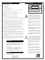
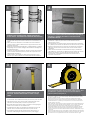
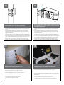
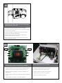
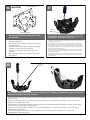
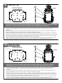
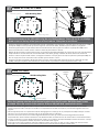
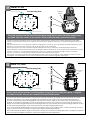
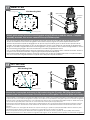
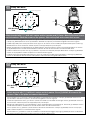
IGLOO DOME
An Air-Conditioned Solution for hot, humid climates
www.videolarm.com
Installation and Operation Instructions for the following models:
IGDW75C1N
Outdoor air conditioned dome housing with wall and pole mount, clear polycarbonate dome, with 240VAC input, heater/blower, 120 to 24VAC transformer for fixed camera
IGDW75T1N
Tinted version
CERTIFIED
Before attempting to connect or operate this product,
please read these instructions completely.
81-IN5434
05-06-2010
IMPORTANT SAFEGUARDS
1
Read these instructions.
2
Keep these instructions.
3
Heed all warnings
4
Follow all instructions.
5
Do not use this apparatus near water.
6
Clean only with damp cloth.
7
Do not block any of the ventilation openings. Install in accordance with the
SAFETY PRECAUTIONS
CAUTION
RISK OF ELECTRIC SHOCK
DO NOT OPEN
manufacturers instructions.
8
Cable Runs- All cable runs must be within permissible distance.
9
Mounting - This unit must be properly and securely mounted to a supporting
structure capable of sustaining the weight of the unit.
Accordingly:
a. The installation should be made by a qualified installer.
b. The installation should be in compliance with local codes.
c. Care should be exercised to select suitable hardware to install the unit, taking into
account both the composition of the mounting surface and the weight of the
unit.
10 Do not install near any heat sources such as radiators, heat registers, stoves, or other
apparatus ( including amplifiers) that produce heat.
11 Do not defeat the safety purpose of the polarized or grounding-type plug. A
polarized plug has two blades with one wider than the other. A grounding type
plug has two blades and a third grounding prong. The wide blade or the third
prong are provided for your safety. When the provided plug does not fit into your
outlet, consult an electrician for replacement of the obsolete outlet.
12 Protect the power cord from being walked on or pinched particularly at plugs,
convenience receptacles, and the point where they exit from the apparatus.
13 Only use attachment/ accessories specified by the manufacturer.
14 Use only with a cart, stand, tripod, bracket, or table specified by the manufacturer,
or sold with the apparatus. When a cart is used, use caution when moving the cart/
apparatus combination to avoid injury from tip-over.
15 Unplug this apparatus during lighting storms or when unused for long periods of time.
16 Refer all servicing to qualified service personnel. Servicing is required when the
apparatus has been damaged in any way, such as power-supply cord or plug is
damaged, liquid has been spilled of objects have fallen into the apparatus, the
apparatus has been exposed to rain or moisture, does not operate normally, or
has been dropped.
Be sure to periodically examine the unit and the supporting structure to make sure that the
integrity of the installation is intact. Failure to comply with the foregoing could result in the
unit separating from the support structure and falling, with resultant damages or injury to
anyone or anything struck by the falling unit.
UNPACKING
Unpack carefully. Electronic components can be
damaged if improperly handled or dropped. If an item
appears to have been damaged in shipment, replace
it properly in its carton and notify the shipper.
Be sure to save:
1 The shipping carton and packaging material.
They are the safest material in which to make
future shipments of the equipment.
2 These Installation and Operating Instructions.
SERVICE
If technical support or service is needed, contact us
at the following number:
TECHNICAL SUPPORT
AVAILABLE 24 HOURS
1 - 800 - 554 -1124
CAUTION: TO REDUCE THE RISK OF
ELECTRIC SHOCK, DO NOT REMOVE
COVER ( OR BACK). NO USER- SERVICEABLE PARTS INSIDE. REFER SEVICING TO
QUALIFIED SERVICE PERSONNEL.
The lightning flash with an arrowhead
symbol, within an equilateral triangle, is
intended to alert the user to the presence
of non-insulated “dangerous voltage”
within the product’s enclosure that may be
of sufficient magnitude to constitute a risk
to persons.
Este símbolo se piensa para alertar al usuario a la
presencia del “voltaje peligroso no-aisIado” dentro del
recinto de los productos que puede ser un riesgo de
choque eléctrico.
Ce symbole est prévu pour alerter I’utilisateur à la
presence “de la tension dangereuse” non-isolée dans la
clôture de produits qui peut être un risque de choc
électrique.
Dieses Symbol soll den Benutzer zum Vorhandensein der
nicht-lsolier “Gefährdungsspannung” innerhalb der
Produkteinschließung alarmieren die eine Gefahr des
elektrischen Schlages sein kann.
Este símbolo é pretendido alertar o usuário à presença
“di tensão perigosa non-isolada” dentro do cerco dos
produtos que pode ser um risco de choque elétrico.
Questo simbolo è inteso per avvertire I’utente alla
presenza “di tensione pericolosa” non-isolata all’interno
della recinzione dei prodotti che può essere un rischio di
scossa elettrica.
The exclamation point within an equilateral
triangle is intended to alert the user to
presence of important operating and
maintenance (servicing) instructions in the
literature accompanying the appliance.
Este símbolo del punto del exclamation se piensa para
alertar al usuario a la presencia de instrucciones
importantes en la literatura que acompaña la
aplicación.
Ce symbole de point d’exclamation est prévu pour
alerter l’utilisateur à la presence des instructions
importantes dans la littérature accompagnant
l’appareil.
Dieses Ausruf Punktsymbol soll den Benutzer zum
Vorhandensein de wichtigen Anweisungen in der
Literatur alarmieren, die das Gerät begleitet.
Este símbolo do ponto do exclamation é pretendido
alertar o usuário à presença de instruções importantes
na literatura que acompanha o dispositivo.
Questo simbolo del punto del exclamaton è inteso per
avvertire l’utente alla presenza delle istruzioni importanti
nella letteratura che accompagna l'apparecchio.
LIMITED WARRANTY FOR VIDEOLARM INC. PRODUCTS
VIDEOLARM INC. warrants this Product to be free from defects in material or workmanship,as follows:
PRODUCTCATEGORY
PARTS
LABOR
All Enclosuresand Electronics
Five (5) Years
Five (5) Years
Pan/Tilts
Three (3) Years **6 months if used in autoscan
Three (3) Years **6 months if used in autoscan
/tour operation
Poles/PoleEvators
Three (3) Years /tour operation
Three (3) Years
Warrior/Q-View/I.R.Illuminators
Five (5) Years
Five (5) Years
Five (5) Years **6 months if used in autoscan
SView Series
Five (5) Years **6 months if used in autoscan
/tour operation
Controllers
Five (5) Years /tour operation
Five (5) Years
PowerSupplies
Five (5) Years
Five (5) Years
AccessoryBrackets
Five (5) Years
Five (5) Years
During the labor warranty period, to repair the Product,Purchaserwill either return the defective product, freight prepaid, or deliver it to Videolarm Inc.
an equal degree of protection with a
Decatur GA.The Productto be repaired is to be returned in either its original carton or a similar package
RMA# (Return Materials Authorization number) displayed on the outer box or packing slip. To obtain a RMA#you must contact our TechnicalSupport
Team at 800.554.1124,extension 101.Videolarm will return the repaired Productfreight prepaid to Purchaser.Videolarm is not obligated to provide
Purchaserwith a substitute unit during the warranty period or at any time. After the applicable warranty period, Purchasermust pay all labor and/or
parts charges.
The limited warranty stated in these product instructions is subject to all of the following terms and conditions:
TERMS AND CONDITIONS
1. NOTIFICATIONOF CLAIMS: WARRANTYSERVICE: If Purchaser believes that the Product is defective in material or workmanship, then written notice
with an explanation of the claim shall be given promptly by Purchaser to Videolarm but all claims for warranty service must be made within the
warranty period. If after investigation Videolarm determines that the reported problem was not covered by the warranty, Purchaser shall pay Videolarm
for the cost of investigating the problem at its then prevailing per incident billable rate. No repair or replacement of any Product or part thereof shall
extend the warranty period as to the entire Product. The
warranty on the repaired part only shall be in
for a period of ninety (90) days
following the repair or replacement of that part or the remaining period of the Product parts warranty, whichever is greater.
2. EXCLUSIVE REMEDY: ACCEPTANCE:Purchaser’s exclusive remedy and Videolarm’s sole obligation is to supply (or pay for) all labor necessary to repair
any Product found to be defective within the warranty period and to supply, at no extra charge, new or rebuilt replacements for defective parts.
3. EXCEPTIONS TO LIMITED WARRANTY: Videolarm shall have no liability or obligation to Purchaser with respect to any Product requiring service
during the warranty period which is subjected to any of the following: abuse, improper use: negligence, accident, lightning damage or other acts
of God (i.e., hurricanes, earthquakes),
failure of the end-user to follow the directions outlined in the product instructions, failure of the
end-user to follow the maintenance procedures recommended by the International Security Industry Organization, written in product instructions,
for regular
or recommended in the service manual for the Product. Furthermore, Videolarm shall have no liability where a schedule is
replacement or maintenance or cleaning of certain parts (based on usage) and the end-user has failed to follow such schedule; attempted repair by
personnel; operation of the Product outside of the published environmental and electrical parameters, or if such Product’s original
(trademark, serial number) markings have been defaced, altered, or removed. Videolarm excludes from warranty coverage Products sold
AS IS and/or WITH ALL FAULTS and excludes used Products which have not been sold by Videolarm to the Purchaser. All software and accompanying
documentation furnished with, or as part of the Product is furnished “AS IS” (i.e., without any warranty of any kind), except where expressly provided
otherwise in any documentation or license agreement furnished with the Product.
4. PROOF OF PURCHASE: The Purchaser’s dated bill of sale must be retained as evidence of the date of purchase and to establish warranty eligibility.
DISCLAIMEROF WARRANTY
EXCEPT FOR THE FOREGOING WARRANTIES, VIDEOLARM HEREBY DISCLAIMS AND EXCLUDES ALL OTHER WARRANTIES, EXPRESS OR IMPLIED,
INCLUDING, BUT NOT LIMITED TO ANY AND/OR ALL IMPLIED WARRANTIES OF MERCHANTABILITY, FITNESS FOR A PARTICULAR PURPOSE AND/OR ANY WARRANTY WITH
REGARD TO ANY CLAIM OF INFRINGEMENT THAT MAY BE PROVIDED IN SECTION 2-312(3) OF THE UNIFORM COMMERCIAL CODE AND/OR IN ANY OTHER COMPARABLE
STATE STATUTE. VIDEOLARM HEREBY DISCLAIMS ANY REPRESENTATIONS OR WARRANTY THAT THE PRODUCT IS COMPATIBLE WITH ANY COMBINATION OF NON-VIDEOLARM
PRODUCTS OR NON-VIDEOLARM RECOMMENDED PRODUCTS PURCHASER CHOOSES TO CONNECT TO PRODUCT.
LIMITATION OF LIABILITY
THE LIABILITY OF VIDEOLARM, IF ANY, AND PURCHASER’S SOLE AND EXCLUSIVE REMEDY FOR DAMAGES FOR ANY CLAIM OF ANY KIND
WHATSOEVER, REGARDLESS OF THE LEGAL THEORY AND WHETHER ARISING IN TORT OR CONTRACT, SHALL NOT BE GREATER THAN THE ACTUAL PURCHASE PRICE OF THE
PRODUCT WITH RESPECT TO WHICH SUCH CLAIM IS MADE. IN NO EVENT SHALL VIDEOLARM BE LIABLE TO PURCHASER FOR ANY SPECIAL, INDIRECT, INCIDENTAL, OR
CONSEQUENTIAL DAMAGES OF ANY KIND INCLUDING, BUT NOT LIMITED TO, COMPENSATION, REIMBURSEMENT OR DAMAGES ON ACCOUNT OF THE LOSS OF PRESENT
OR PROSPECTIVE PROFITS OR FOR ANY OTHER REASON WHATSOEVER.
!
English
Español
Français
Deutsch
Portuguese
Italiano
Electrical Specifications
Mechanical Options
Igloo Dome
Power 120VAC .
50/60 H2.
300 WATTS.
Tools Required: Phillips Head Screwdriver.
Ceiling Support Wires(14 AWG wire min.)
Energía 120VAC.
50/60 H2.
300 VATIOS.
Las herramientas requirieron: Destornillador principal
Phillips.
Alambres de la ayuda del techo
(14 de alambre del AWG Min.)
Puissance 120VAC.
50/60 H2.
300 WATTS.
Outils requis : Tournevis phillips.
Fils de soutien de plafond (14 de fil d'A.W.G. mn)
Energie 120VAC.
50/60 H2.
300 WATT.
Werkzeuge erfordert: Kreuzkopfschraubenzieher.
Decken-Stützdrähte (14 AWG-Lehredraht Min.)
Poder 120VAC.
50/60 de H2.
300 WATTS.
As ferramentas exigiram: Chave de fenda principal de
Phillips.
Fios da sustentação do teto
(14 de fio Calibre de diâmetro de fios Min.)
Potere 120VAC.
50/60 di H2.
300 WATT.
Gli attrezzi hanno richiesto: Cacciavite phillips. Legare
di sostegno del soffitto
(14 del legare dell'AWG min.)
1. Air flow sensor available to be combined with camera output systems
to monitor the effectiveness of air filter. If improper air flow is detected,
sensor will send alarm. If user by passes air flow sensor, air filter should
be changed approximately every 6 months (depending on monitoring
environment).
2. The Igloo Dome incorporates an automatic cool-down safety
precaution system which deactivates the power of both the camera and
cooling system when internal temperatures exceed 167°F (75°C). Once
safe operating conditions resume, the camera and cooling system will
reactivate.
3. Condensation and water run-off is a by product of the Igloo Dome's
cooling system. To prevent damage to the internal electrical
components, the Igloo Dome consists of a water run-off hose, located
underneath the optical dome. Please use caution that small amounts of
water accumulation will be present directly underneath the Igloo Dome,
resulting in slippery conditions.
* A 50/50 blend of propylene glycol and water has a freezing point of
-26°F. If lower temperature protection is required, it can readily be
attained by increasing the concentration of propylene glycol Antifreeze for example; a 60/40 blend of Antifreeze and water gives antifreeze
protection to -54°F.
Content of Box
COOLANT
1
2
1/2" LOWER
MOUNTING BOLTS
STEP 1:
POSITION LOWER MOUNTING BOLTS, WASHERS
Thread one retainer extrusion at the end of steel band,
allowing 1” (254mm) of band out. Beveled end of
extrusion to be out.
AND NUTS
AS SHOWN ABOVE.,
THREAD THE NUTS
Position lower mounting
bolts,
washers
and nuts as
UNTIL FLUSH WITH BOLT ENDS
shown above. Thread the nuts until flush with bolt ends.
• Coloque pernos, arandelas y tuercas más bajos de montaje como se
muestra arriba. Rosque las tuercas hasta rubor con los extremos de
perno.
• Placez les boulons de fixation, les rondelles et les écrous inférieurs
comme montré ci-dessus. Filetez les écrous jusqu'à l'éclat avec des
extrémités de boulon.
• Bringen Sie unterere Befestigungsbolzen, Unterlegscheiben und Nüsse
wie gezeigt oben in Position. Verlegen Sie die Nüsse bis bündiges mit
Schraubbolzenenden.
• Posicione uns mais baixos parafusos, arruelas e porcas de montagem
como mostrado acima. Rosqueie as porcas até o resplendor com
extremidades de parafuso.
• Posizioni i bulloni, le rondelle ed i dadi più bassi di attacco come
indicato sopra. Filetti i dadi fino ad a livello dell'estremità di bullone.
• Un hilo de retención de extrusión en la final de la banda de acero,
permitiendo 1 "(254 mm), de banda a cabo. Biselados final de
extrusión que se fuera.
• Thread extrusion une retenue à la fin de la bande d'acier, permettant
à 1 "(254mm) de la bande de. Biseauté fin de l'extrusion de ne pas être.
• Rijg een vasthoud-extrusie op het einde van stalen band, waardoor 1
"(254 mm) van de band uit. Schuine einde van de extrusie worden
uitgesloten.
• Passe um retentor extrusão no final da banda de aço, permitindo 1
"(254 milímetros), da banda fora. Biselado final de extrusão de ser fora.
• Iniziatore di estrusione uno fermo alla fine di banda di acciaio,
consentendo 1 "(254 millimetri) di banda fuori. Smussato fine di
estrusione di essere fuori.
3
Carefully bend steel band around beveled end of
extrusion. Hammer bend band to create a sharp
radius.
• Doblar cuidadosamente alrededor de banda de acero biselado final
de la extrusión. Libra doblado la banda para crear un plano de radio.
• Plier soigneusement autour de la bande d'acier biseautée fin de
l'extrusion. Livre bande pliée pour créer un plat de rayon.
• Buig stalen band rond schuine einde van extrusie. Pound gebogen
band voor het maken van een vlakke straal.
• Cuidadosamente dobre aço biselado fim da banda em torno de
extrusão. Libra curvados banda para criar um plano de raio.
• Attentamente piegare acciaio banda intorno smussato fine di
estrusione. Sterlina piegato banda per creare un piatto raggio.
4
Measure perimeters around pole at desired mounting location.
Measure band from outside edge of threaded retainer extrusion. Allow
for additional 1½” (254 mm) to be placed underneath additional
extrusion. Mark steel band and cut.
• Medida de distancias en torno a polos de montaje en la ubicación deseada.
•
•
•
•
Medida de fuera de banda borde de la rosca de retención de extrusión. Dejar
para más 1½ "(254 mm), que se coloca debajo adicionales de extrusión. Marcos
de acero y banda de corte.
Mesurer les distances autour de pôles de montage à l'emplacement désiré.
Mesure bande de bord extérieur de l'extrusion de retenue fileté. Pour permettre
supplémentaire de 1½ "(254 mm) pour être placées sous d'autres extrusion. Mark
bande d'acier et de coupe.
Meet afstanden rond de paal te monteren gewenste locatie. Maatregel band van
buiten de rand van het threaded vasthoud-extrusie. Laat voor extra 1½ "(254 mm)
worden geplaatst onder meer extrusie. Mark stalen band en uitgesneden.
Medida de distâncias de cerca de pólo na montagem local desejado. Medida
banda de fora de borda enfiada retentor extrusão. Permitir adicionais para 1½
"(254 mm) devem ser colocados debaixo adicionais extrusão. Mark banda de aço
e de corte.
Misura le distanze intorno al polo di montaggio posizione desiderata. Misura banda
al di fuori del bordo del fermo filettati estrusione. Consenti per ulteriori 1½ "(254 mm)
ad essere messi sotto supplementari estrusione. Mark acciaio banda e taglio.
•
•
•
•
•
5
6
Thread mounting hardware and additional retainer extrusion
at opposite end of steel band. Refer to Block 1 and 2 for
instructions.
Place assembly around pole at desired mounting location.
Insert bolt through retainer extrusions. Head of bolt needs to
lock into end of retainer.
Rosca de montaje de hardware adicional y anticipo de extrusión en el
extremo opuesto de la banda de acero. Consulte a Bloque 1 y 2 para
obtener instrucciones.
Thread matériel de montage et de retenue supplémentaire d'extrusion
à face en acier fin de bande. Reportez-vous à bloc 1 et 2 pour les
instructions.
Rijg de montage van extra hardware en vasthoud-extrusie op het
andere uiteinde van stalen band. Raadpleeg Blok 1 en 2 voor
instructies.
Rosca de montagem e hardware adicional retentor extrusão na
extremidade oposta da banda de aço. Referem-se Bloco 1 e 2 para
obter instruções.
Iniziatore di montaggio e supplementari fermo estrusione a fine opposta
fascia di acciaio. Fare riferimento al blocco 1 e 2 per le istruzioni.
7
Thread nut to end of bolt and tighten with wrench.
• Hilo para poner fin a la tuerca de tornillo y apretar con llave.
• Thread noix à la fin de boulon et serrez avec clé.
• Thread moer tot het einde van de bout en draai met de moersleutel.
• Thread porca para o fim do ferrolho e aperte com a chave inglesa.
• Iniziatore dado alla fine del bullone e serrare con la chiave inglese.
•
•
•
•
•
Lugar de reunión en torno a polos de montaje en la ubicación deseada.
Inserte el perno de retención a través de extrusiones. Jefe de la saeta a las
necesidades de bloqueo en la final del retenedor.
Lieu de rassemblement autour de pôles de montage à l'emplacement désiré.
Insérer boulon de retenue extrusions. Chef de boulon doit en fin de verrouillage de la bague de retenue.
Plaats vergadering rond de paal te monteren gewenste locatie. Plaats bout
door vasthoud extrusies. Hoofd van de bout moet vastklikken einde van
vasthoud.
Colocar cerca de montagem em poste montagem local desejado. Inserir
ferrolho através retentor extrusões. Chefe do ferrolho precisa ser encaixado na
extremidade do dispositivo de retenção.
Luogo di montaggio intorno al polo di montaggio posizione desiderata.
Inserire il bullone attraverso fermo estrusioni. Capo del bullone deve bloccare
in fine di fermo.
8
Installation is complete when nut is tight / secure and all slack has been removed from steel band.
• La instalación es completa cuando es apretado la tuerca / garantizar la seguridad de todos y la atonía se ha eliminado de la banda
de acero.
• L'installation est terminée lorsque l'écrou est serré, sécurité et tous les mou a été retiré de la bande d'acier.
• De installatie is volledig wanneer moer is strak / beveiligde en alle speling verwijderd is van staal-band.
• A instalação está completa quando porca é apertado / seguro e todos folga foi removido da banda de aço.
• L'installazione è completa quando il dado è stretto / e tutte le sicuro slack è stata rimossa dalla banda di acciaio.
9
From
10
A-Z
Repeat for multiple band applications.
(4) holes
Locate and drill (4) holes 2” deep
• Repetición para los usos de venda múltiples.
• Localice y perfore (4) los agujeros 2” profundamente
• Répétition pour des applications de bande multiples.
•
Trouvez et forez (4) les trous 2 » profondément
• Wiederholung für mehrfache Bandanwendungen.
•
Lokalisieren Sie und bohren Sie (4) Löcher 2“ tief
•
Encontre e perfure (4) furos 2” profundamente
•
Individui e perfori (4) fora 2„ in profondità
• Repetição para aplicações de faixa múltiplas.
• Ripetizione per le applicazioni di fascia multiple.
11
Place the mounting plate against the wall
12
Attach with (4) anchor bolts, (4) lock washers, and (4)
flat washers
• Fijación con (4) los pernos de ancla, (4) arandelas de cerradura, y (4) arandelas
planas
• Coloque la pletina contra la pared
•
Placez le plat de support contre le mur
•
Setzen Sie die Montageplatte gegen die Wand
•
Coloc a placa de montagem de encontro à parede
•
Disponga il giunto di supporto contro la parete
•
Attache avec (4) des boulons d'anchrage, (4) rondelles de freinage, et (4) rondelles
plates
•
Befestigung mit (4) Ankerbolzen, (4) Federringe und (4) flache Unterlegscheiben
•
Anexo com (4) parafusos de escora, (4) arruelas de fechamento, e (4) arruelas lisas
•
Attaccatura con (4) bulloni d'ancoraggio, (4) ranelle di bloccaggio e (4) rondelle
piane
13
14
Tighten all bolts securely
Hang the Igloo Dome unit onto the wall mount
• Apriete todos los pernos con seguridad
•
Serrez tous les boulons solidement
•
Ziehen Sie alle Schraubbolzen sicher fest
•
Aperte todos os parafusos firmemente
•
Stringa saldamente tutti i bulloni
• Cuelgue la unidad Deputy2 sobre el montaje de la pared
•
Accrochez l'unité Igloo Dome sur le bâti de mur
•
Hängen Sie die Iglu-Haubemaßeinheit auf die Wandeinfassung
•
Pendure a unidade da abóbada do Igloo na montagem da parede
•
Appenda l'unità Igloo Dome sul supporto della parete
15
16
3/8" UPPER
MOUNTING BOLTS
SLOTS ON
MOUNTING PLATE
STEP 2:
REST THE IGLOODOME UPPER MOUNTING BOLTS
ON THE SLOTS OF THE ADAPTER PLATE.
INSERT LOWER BOLTS, WASHERS AND NUTS AND
TIGHTEN ALL FOUR BOLTS
STEP 1:
MOUNT ADAPTER PLATE TO POLE BY STEEL STRAPS
Mount adapter plate to pole by steel straps
• Coloque pernos, arandelas y tuercas más bajos de montaje como se
muestra arriba. Rosque las tuercas hasta rubor con los extremos de
perno.
• Placez les boulons de fixation, les rondelles et les écrous inférieurs
comme montré ci-dessus. Filetez les écrous jusqu'à l'éclat avec des
extrémités de boulon.
• Bringen Sie unterere Befestigungsbolzen, Unterlegscheiben und Nüsse
wie gezeigt oben in Position. Verlegen Sie die Nüsse bis bündiges mit
Schraubbolzenenden.
• Posicione uns mais baixos parafusos, arruelas e porcas de montagem
como mostrado acima. Rosqueie as porcas até o resplendor com
extremidades de parafuso.
• Posizioni i bulloni, le rondelle ed i dadi più bassi di attacco come
indicato sopra. Filetti i dadi fino ad a livello dell'estremità di bullone.
17
Release latches (2) to open the cover
• Cierres de lanzamiento (2) para abrir la cubierta
• Verrous de dégagement (2) pour ouvrir la couverture
Rest the IglooDome upper mounting bolts on the slots of
the adapter plate. Insert lower bolts, washers and nuts
and tighten all (4) bolts
• Coloque pernos, arandelas y tuercas más bajos de montaje como se
muestra arriba. Rosque las tuercas hasta rubor con los extremos de
perno.
• Placez les boulons de fixation, les rondelles et les écrous inférieurs
comme montré ci-dessus. Filetez les écrous jusqu'à l'éclat avec des
extrémités de boulon.
• Bringen Sie unterere Befestigungsbolzen, Unterlegscheiben und Nüsse
wie gezeigt oben in Position. Verlegen Sie die Nüsse bis bündiges mit
Schraubbolzenenden.
• Posicione uns mais baixos parafusos, arruelas e porcas de montagem
como mostrado acima. Rosqueie as porcas até o resplendor com
extremidades de parafuso.
• Posizioni i bulloni, le rondelle ed i dadi più bassi di attacco come
indicato sopra. Filetti i dadi fino ad a livello dell'estremità di bullone.
18
Support cover in open position using the brace
• Apoye la cubierta en la posición abierta usando el apoyo
• Soutenez la couverture en position d'ouverture utilisant le croisillon
• Entriegelungshebel (2), zum der Abdeckung zu öffnen
• Stützen Sie Abdeckung in der geöffneten Position unter Verwendung
der Klammer
• Travas de liberação (2) para abrir a tampa
• Suporte a tampa na posição aberta usando a cinta
• Fermi di rilascio (2) aprire la copertura
• Sostenga la copertura nella posizione aperta usando il gancio
19
STEP 3:
COMPLETE ELECTRICAL CONNECTIONS
Route power and video cables through the water tight
feed (at the base of the unit)
• Encamine los cables de la energía y del vídeo a través de la
alimentación apretada del agua (en la base de la unidad)
• Conduisez les câbles de puissance et de vidéo par l'alimentation serrée
de l'eau (à la base de l'unité)
• Verlegen Sie Energien- und Videokabel durch die feste Zufuhr des
Wassers (an der Unterseite der Maßeinheit)
• Distribua cabos do poder e do vídeo através da alimentação
apertada da água (na base da unidade)
• Diriga i cavi del video e di potere attraverso l'alimentazione stretta
dell'acqua (alla base dell'unità)
20
INPUT
OUTPUT
GND
GND
N
N
L
L
Connect wires as shown, use minimum of 14 AWG
Route cables and connect as shown
• Conecte los alambres como se muestra, utilice el mínimo de AWG 14
• Encamine los cables y conecte como se muestra
• Reliez les fils comme montré, employez le minimum d'A.W.G. 14
• Conduisez les câbles et reliez comme montré
• Schließen Sie Drähte wie gezeigt an, verwenden Sie Minimum von
AWG-Lehre 14
• Verlegen Sie Kabel und schließen Sie wie gezeigt an
• Conecte fios como mostrado, use um mínimo de Calibre de diâmetro de
fios 14
• Colleghi i legare come indicato, usi un minimo dell'AWG 14
• Distribua cabos e conecte-os como mostrado
• Diriga i cavi e colleghi come indicato
21
Remove right side louver panel
22
Set louver aside
• Quite el panel de la lumbrera del derecho
• Fije la lumbrera a un lado
• Enlevez le panneau d'auvent de côté droit
• Placez l'auvent de côté
• Entfernen Sie Luftschlitzverkleidung der rechten Seite
• Stellen Sie Luftschlitz beiseite ein
• Remova o painel da grelha do lado direito
• Ajuste a grelha de lado
• Rimuova il pannello della feritoia della parte di destra
• Regoli la feritoia da parte
23
Remove cap and still reservoir with Propylene Glycol/
water mix. Use mix ratio specified or container (*)
• Quite el casquillo y aún el depósito con la mezcla del glicol/del agua
de propileno. Utilice el cociente de la mezcla especificado o el
envase
• Enlevez le chapeau et toujours le réservoir avec le mélange de
propylèneglycol/eau. Utilisez le rapport de mélange spécifique ou le
récipient
• Entfernen Sie Kappe und noch Vorratsbehälter mit Propylenglykol-/wassermischung. Benutzen Sie das spezifizierte Mischungsverhältnis
oder Behälter
• Remova o tampão e ainda o reservatório com a mistura do
glicol/água de Propylene. Use a relação da mistura especific ou o
recipiente
• Rimuova la protezione ed ancora il bacino idrico con la miscela del
glicol/acqua di propilene. Utilizzi il rapporto della miscela specificato o
il contenitore
* Refer to the Mechanical Operations section of the instructions for
proper mixture proportions
24
Initial liquid level should be between “High” and “Low”
markers
• El nivel líquido inicial debe estar entre “los marcadores altos” y “bajos”
This is what the typical path of illumination will look like with the setting at 30 degrees.
•
•
•
•
•
• Le niveau liquide initial devrait être entre les « hauts » et « bas »
marqueurs
Esto es lo que parecerá la trayectoria típica de la iluminación con el ajuste 30 grados.
Flüssiges
zuerstniveau sollte
C'est ce qui ressemblera le chemin typique de l'illumination à•avec
l'arrangement
30 zwischen
degrés.„den hohen“ und „niedrigen“
Markierungen sein
Dieses ist, was der typische Weg der Ablichtung wie mit der Einstellung bei 30 Grad aussieht.
Este é o que o trajeto típico da iluminação olhará como com• oOajuste
em 30
graus.
nível líquido
inicial
deve estar entre “marcadores elevados” e
“baixos”
Ciò è che cosa il percorso tipico di illuminazione assomiglierà con
alla regolazione 30 gradi
• Il livello liquido iniziale dovrebbe essere fra “gli alti„ ed indicatori “bassi„
25
Power up the unit by activating the “Primer” button as
shown to circulate coolant through system. Add
coolant after system stabilizes-if required (should be
between the “High” and “Low” marker.
• Accione para arriba la unidad activando el botón de la “cartilla”
como se muestra para circular el líquido refrigerador a través de
sistema. Agregue el líquido refrigerador después de sistema estabilizarsi está requerido (debe estar entre “el marcador alto” y “bajo”.
• Mettez l'unité en actionnant le bouton de « amorce » comme montré
pour circuler le liquide réfrigérant par le système. Ajoutez le liquide
réfrigérant après système stabiliser-si requis (devrait être entre le « haut
» et « bas » marqueur.
• Treiben Sie oben die Maßeinheit an, indem Sie wie gezeigt den
„Zündkapsel“ Knopf aktivieren, um Kühlmittel durch System zu verteilen.
Fügen Sie Kühlmittel nach System hinzu, stabilisieren-wenn erfordert
(sollte zwischen der „hohen“ und „niedrigen“ Markierung sein.
• Pnha acima a unidade ativando a tecla da “primeira demão” como
mostrado para circular o líquido refrigerante através do sistema.
Adicione o líquido refrigerante após o sistema estabilizar-se exigido
(deve estar entre “o marcador elevado” e “baixo”.
• Alimenti in su l'unità attivando il tasto “dell'iniettore„ come indicato per
fare circolare il liquido refrigerante attraverso il sistema. Aggiunga il
liquido refrigerante dopo il sistema stabilizzare-se richiesto (dovrebbe
essere fra “l'alto„ ed indicatore “basso„.
26
The air intake filters should be periodically checked.
They should be cleaned or replaced. To replace,
unfasten the nuts holding the filter frame. Replace and
remount using nuts as shown.
This is what the typical path of illumination will look like with the setting at 30 degrees.
• Los filtros de la toma de aire deben ser comprobados periódicamente.
Deben ser limpiados o ser substituidos. Para substituir, desate la
Esto es lo que parecerá la trayectoria típica de la iluminación con
el ajuste
grados.
tenencia
nuts el30
marco
del filtro. Substituya y remonte con tuercas
comol'arrangement
se muestra.
C'est ce qui ressemblera le chemin typique de l'illumination à avec
30 degrés.
•
•
• Dieses ist, was der typische Weg der Ablichtung wie mit der Einstellung bei 30 Grad aussieht.
• Les filtres d'entrée d'air devraient être périodiquement vérifiés. Ils
• Este é o que o trajeto típico da iluminação olhará como com odevraient
ajuste em
graus.
être 30
nettoyés
ou remplacés. Pour remplacer, desserrez
• Ciò è che cosa il percorso tipico di illuminazione assomiglierà con
alla regolazione
30 de
gradi
l'exploitation
nuts l'armature
filtre. Remplacez et remount à l'aide
des écrous comme montrés.
• Die Lufteintritfilter sollten regelmäßig überprüft werden. Sie sollten
gesäubert werden oder ersetzt werden. Um zu ersetzen, lösen Sie die
nuts Holding der Filterrahmen. Ersetzen Sie und remount mit Nüssen wie
gezeigt.
• Os filtros da entrada de ar devem periòdicamente ser verific. Devem
ser limpados ou substituído. Para substituir, desate a terra arrendada
nuts o frame do filtro. Substitua e remount usando porcas como
mostradas.
• I filtri dalla presa di aria dovrebbero essere controllati periodicamente.
Dovrebbero essere puliti o sostituiti. Per sostituire, sciolga la tenuta nuts
la struttura del filtro. Sostituisca e remount per mezzo dei dadi come
indicati.
27
Mount louver panel(s)
• Los paneles de la lumbrera del montaje
• Panneaux d'auvent de bâti
• Einfassungsluftschlitzverkleidungen
• Painéis da grelha da montagem
• Pannelli della feritoia del supporto
28
17
Axis 213
(3) #8x3/8”
(13mm) ½"
2539 Mounting Plate
Captive
Screw
(26mm) 1"
(52mm) 2"
Mounting
Hole
Mounting
Hole
Install the camera to the mounting plate with (2) #10 screws and lock washers provided. Place (3)
#8x3/8” screws on the spacers and align the mounting slots. Slide on plate and camera then secure.
• Instale la cámara fotográfica a la placa de montaje con (2) los tornillos #10 y las arandelas de cerradura proporcionadas. Coloque los
tornillos de (3) del # 8x3/8"en los espaciadores y alinee las ranuras de montaje. Resbale en la placa y la cámara fotográfica entonces
seguras.
• Installez l'appareil-photo sur le plat de support avec (2) les vis #10 et les rondelles de freinage fournies. Placez les vis de (3) # de 8x3/8"
sur les entretoises et alignez les fentes de support. Glissez du plat et de l'appareil-photo puis bloqués.
• Bringen Sie die Kamera zur Montageplatte mit (2) den bereitgestellten Schrauben #10 und Federringen an. Setzen Sie (3) # 8x3/8"die
Schrauben auf die Distanzscheiben und richten Sie die Befestigungsschlitze aus. Schieben Sie auf die sichere Platte und Kamera dann.
• Instale a câmera à placa de montagem com (2) os parafusos #10 e as arruelas de fechamento fornecidas. Coloque os parafusos de
(3) # de 8x3/8"nos espaçadores e alinhe os entalhes de montagem. Deslize na placa e na câmera então seguras.
• Installi la macchina fotografica al giunto di supporto con (2) le viti #10 e le ranelle di bloccaggio fornite. Disponga le viti di 8x3/8"# di (3)
sui distanziatori ed allinei le scanalature di montaggio. Faccia scorrere sulla piastra e sulla macchina fotografica allora sicure.
29
18
Axis 214
Mounting Hole
3026 Mounting
Plate
(3) #8 x 3/8”
Captive
Screw
(52mm) 2"
Mounting
Hole
Mounting
Hole
Install the camera to the mounting plate using (3) 3mm x 12mm bolts and lock washers. Place (3) #8x3/8”
screws on the spacers and line up the mounting slots. Slide plate in and secure.
• Instale la cámara fotográfica a la placa de montaje usando (3) los pernos de 3m m x de 12m m y las arandelas de cerradura.
•
•
•
•
Coloque los tornillos de (3) del # 8x3/8"en los espaciadores y alinee las ranuras de montaje. Resbale la placa adentro y
asegúrela.
Installez l'appareil-photo sur le plat de support en utilisant (3) des boulons de 3mm x de 12mm et des rondelles de freinage.
Placez les vis de (3) # de 8x3/8"sur les entretoises et alignez les fentes de support. Glissez le plat dedans et le fixez.
Bringen Sie die Kamera zur Montageplatte mit (3) 3mm x 12mm den Schraubbolzen und den Federringen an. Setzen Sie (3) #
8x3/8"die Schrauben auf die Distanzscheiben und richten Sie die Befestigungsschlitze aus. Schieben Sie Platte innen und sichern
Sie.
Instale a câmera à placa de montagem usando (3) os parafusos de 3mm x de 12mm e as arruelas de fechamento. Coloque os
parafusos de (3) # de 8x3/8"nos espaçadores e alinhe-os acima dos entalhes de montagem. Deslize a placa dentro e fixe-a.
Installi la macchina fotografica al giunto di supporto usando (3) i bulloni di 12mm x di 3mm e le ranelle di bloccaggio. Disponga
le viti di 8x3/8"# di (3) sui distanziatori ed allinei le scanalature di montaggio. Faccia scorrere la piastra dentro e fissi.
30
Axis 215
1"
1"
Mounting
Holes
Mounting
Holes
2"
Install the camera to the mounting plate with (4) #8 screws and lock washers provided. Place (3) #8x3/8”
screws on the spacers and align the mounting slots. Slide on plate and camera then secure.
• Instale la cámara fotográfica a la placa de montaje con (4) los tornillos #8 y las arandelas de cerradura proporcionadas. Coloque los
tornillos de (3) del # 8x3/8"en los espaciadores y alinee las ranuras de montaje. Resbale en la placa y la cámara fotográfica entonces
seguras.
• Installez l'appareil-photo sur le plat de support avec (4) les vis #8 et les rondelles de freinage fournies. Placez les vis de (3) # de 8x3/8"
sur les entretoises et alignez les fentes de support. Glissez du plat et de l'appareil-photo puis bloqués.
• Bringen Sie die Kamera zur Montageplatte mit (4) den bereitgestellten Schrauben #8 und Federringen an. Setzen Sie (3) # 8x3/8"die
Schrauben auf die Distanzscheiben und richten Sie die Befestigungsschlitze aus. Schieben Sie auf die sichere Platte und Kamera dann.
• Instale a câmera à placa de montagem com (4) os parafusos #8 e as arruelas de fechamento fornecidas. Coloque os parafusos de
(3) # de 8x3/8"nos espaçadores e alinhe os entalhes de montagem. Deslize na placa e na câmera então seguras.
• Installi la macchina fotografica al giunto di supporto con (4) le viti #8 e le ranelle di bloccaggio fornite. Disponga le viti di 8x3/8"# di (3)
sui distanziatori ed allinei le scanalature di montaggio. Faccia scorrere sulla piastra e sulla macchina fotografica allora sicure.
17
31
Axis 231D/232D
Mounting Hole
18
32
AXIS 231-232D
Tab
Loosen
Screw
Mounting
Hole
Mounting
Hole
Use the (3) keyhole slots indicated above.
Loosen the screw to the right of the tab by
approximately (5) turns.
• Utilice (3) las ranuras del ojo de la cerradura indicadas
arriba.
• Employez (3) les fentes de trou de la serrure indiquées
ci-dessus.
• Benutzen Sie die (3) Schlüssellochschlitze, die oben
angezeigt werden.
• Use (3) os entalhes do buraco da fechadura indicados
acima.
• Usi (3) le scanalature del buco della serratura indicate
sopra.
• Afloje el tornillo a la derecha de la lengüeta aproximadamente (5) vueltas.
• Desserrez la vis à la droite de l'étiquette approximativement (5) aux tours.
• Lösen Sie die Schraube auf der rechten Seite des
Vorsprunges durch ungefähr (5) Umdrehungen.
• Afrouxe o parafuso à direita da aba aproximadamente (5) por voltas.
• Allenti la vite alla destra della linguetta circa (5) dalle
girate.
19
33
Locking Screw
Captive
Screw
Keyhole
Slot (3)
Locking
Pins
(3) #8 x 3/8”
(13mm) ½"
Position locking pins and locking screw over slots and turn clockwise; secure the screw. Place (3)
#8x3/8” screws on the spacers and line up mounting slots. Slide on plate and camera then secure.
• Coloque los pernos de fijación y el tornillo de fijación sobre ranuras y dé vuelta a la derecha; asegure el tornillo. Coloque los tornillos de
(3) del # 8x3/8"en los espaciadores y las ranuras de montaje de la formación. Resbale en la placa y la cámara fotográfica y asegure.
• Placez les chevilles de verrouillage et la vis de blocage au-dessus des fentes et tournez dans le sens des aiguilles d'une montre ; fixez la
vis. Placez les vis de (3) # de 8x3/8"sur les entretoises et les fentes de support de ligne. Glissez du plat et de l'appareil-photo et fixez.
• Bringen Sie Sicherungsstifte und Sicherungsschraube über Schlitzen in Position und drehen Sie nach rechts; sichern Sie die Schraube.
Setzen Sie (3) # 8x3/8"die Schrauben auf die Distanzscheiben und die Anordnungbefestigungsschlitze. Schieben Sie auf Platte und
Kamera und sichern Sie.
• Posicione os pinos travando e o parafuso travando sobre entalhes e gire-os no sentido horário; fixe o parafuso. Coloque os parafusos
de (3) # de 8x3/8"nos espaçadores e alinhe-os acima dos entalhes de montagem. Deslize na placa e na câmera e fixe.
• Posizioni i perni di bloccaggio e la vite di bloccaggio sopra le scanalature e giri in senso orario; fissi la vite. Disponga le viti di 8x3/8"# di
(3) sui distanziatori e sulle scanalature di montaggio dell'allineamento. Faccia scorrere sulla piastra e sulla macchina fotografica e fissi.
20
34
Connection
Module
3mm
Screw
Power
Board
Remove
thethe
power
board
located
inside the
thesetting
connection
module as shown.
This is what
typical
path
of illumination
willhousing.
look likeAttach
with the
at 30 degrees.
Attach this assembly to the housing using (1) 6-32x3/8” screw and star washer.
• Quite a tablero de energía situado dentro de la cubierta. Una el módulo de la conexión según lo demostrado. Una
a esta asamblea a la cubierta usando (1) "arandela del tornillo 6-32x3/8 y de la estrella.
• Enlevez carte d'alimentation situé à l'intérieur du logement. Attachez le module de raccordement comme montré.
Attachez cette assemblée au logement en utilisant (1) la "vis 6-32x3/8 et tenez le premier rôle la rondelle.
• Entfernen Sie das Energie Brett, das innerhalb des Gehäuses befunden wird. Bringen Sie das Anschlußmodul an, wie
gezeigt. Bringen Sie diese Versammlung zum Gehäuse mit (1) "Schraube 6-32x3/8 und Sternunterlegscheibe an.
• Remova a placa de poder situada dentro da carcaça. Una o módulo da conexão como mostrado. Una este
conjunto à carcaça usando (1) do "arruela parafuso 6-32x3/8 e da estrela.
• Rimuova il bordo di alimentazione situato all'interno dell'alloggiamento. Fissi il modulo del collegamento come
indicato. Fissi questo complessivo all'alloggiamento usando (1) "rondella della vite 6-32x3/8 e della stella.
35
Open Screw
Slots
POWER
1
Camera Power (24VAC)
Red
2
Camera Power (24VAC)
Orange
Cable
Ties
CONTROL
RJ45 Ethernet Connector
ALARMS
1
Alarm 1
Blue
2
Alarm 2
Violet
3
Alarm 3
Gray
4
Common
White
Captive
Screw
Complete
thetypical
wiring
to of
camera.
Attach
thelike
camera
the housing by sliding the (3)
This is what the
path
illumination
will look
with the assembly
setting at 30 to
degrees.
open screw slots over the screws in the housing; tighten the fasteners on the bracket.
• Termine el cableado a la cámara fotográfica. Una el montaje de la cámara fotográfica a la cubierta resbalando
(3) las ranuras abiertas del tornillo sobre los tornillos en la cubierta; apriete los sujetadores en el soporte.
• Accomplissez le câblage à l'appareil-photo. Attachez l'appareil-photo au logement en glissant (3) les fentes
ouvertes de vis au-dessus des vis dans le logement ; serrez les attaches sur la parenthèse.
• Führen Sie die Verdrahtung zur Kamera durch. Bringen Sie die Kamera zum Gehäuse an, indem Sie die (3) geöffneten Schraube Schlitze über den Schrauben im Gehäuse schieben; ziehen Sie die Befestiger am Haltewinkel fest.
• Termine a fiação à câmera. Una o conjunto da câmera à carcaça deslizando (3) os entalhes abertos do parafuso
sobre os parafusos na carcaça; aperte os prendedores no suporte.
• Completi i collegamenti alla macchina fotografica. Fissi il complessivo della macchina fotografica all'alloggiamento
facendo scorrere (3) le scanalature aperte della vite sopra le viti nell'alloggiamento; stringa i fermi sulla staffa.
36
Axis 233D
37
Mounting Hole
Power
Board
Mounting Hole
Disconnect the orange, red, and black wires. Remove the
power board in the housing by loosening screws on the
terminal block and the (4) machine screws.
Use the holes indicated above to mount
the camera.
• Utilice los agujeros indicados arriba para montar la
cámara fotográfica.
• Employez les trous indiqués ci-dessus pour monter
l'appareil-photo.
• Benutzen Sie die Bohrungen, die oben angezeigt
werden, um die Kamera anzubringen.
• Use os furos indicados acima para montar a
câmera.
• Usi i fori indicati sopra per montare la macchina
fotografica.
38
•
•
•
•
•
Desconecte los alambres anaranjados, rojos, y negros. Quite a tablero de
energía en la cubierta aflojando los tornillos en el bloque de terminales y (4)
los tornillos de la máquina.
Débranchez les fils oranges, rouges, et noirs. Enlevez carte d'alimentation
dans le logement en desserrant des vis sur le TB et (4) les vis de machine.
Trennen Sie die orange, roten und schwarzen Leitungen. Entfernen Sie das
Energie Brett im Gehäuse, indem Sie Schrauben am Klemmenblock und an
den (4) Maschine Schrauben lösen.
Desconecte os fios alaranjados, vermelhos, e pretos. Remova a placa de
poder na carcaça afrouxando os parafusos no bloco terminal e (4) nos
parafusos da máquina.
Stacchi i legare arancioni, rossi e neri. Rimuova il bordo di alimentazione
nell'alloggiamento allentando le viti sul blocchetto terminali e (4) sulle viti
della macchina.
Mounting
Bracket
½"
Now remove the mounting bracket and attach (4) 1/2” spacers (located in the packet that came
with the housing) to the base bracket.
• Ahora quite el soporte de montaje y una (4) los espaciadores del 1/2"(situados en el paquete que vino con la cubierta)
al soporte bajo.
• Maintenant enlevez le support et attachez (4) les entretoises de 1/2"(situées dans le paquet qui est venu avec le
logement) à la parenthèse basse.
• Jetzt entfernen Sie die Schienenplatte und bringen Sie (4) die 1/2"Distanzscheiben (gelegen im Paket, das mit dem
Gehäuse kam), zum niedrigen Haltewinkel an.
• Agora remova o suporte de montagem e una (4) os espaçadores de 1/2"(situados no pacote que veio com a
carcaça) ao suporte baixo.
• Ora rimuova il supporto di attacco e fissi (4) i distanziatori di 1/2"(situati nel pacchetto che è venuto con
l'alloggiamento) alla staffa bassa.
39
Quick Release
Plate
Additional
Spacers
Keyhole
Slots
Camera
Bracket
Base Bracket
Mount
the Axis
camera
and quick
release
plate
theatadditional
spacers from
This is what
the 233D
typical
path ofbracket
illumination
will look
like with
theusing
setting
30 degrees.
the hardware packet.
• Monte el soporte de la cámara fotográfica del eje 233D y la placa rápida del lanzamiento usando los espaciadores
adicionales del paquete del hardware.
• Montez la parenthèse d'appareil-photo de l'axe 233D et le plat rapide de dégagement en utilisant les entretoises
additionnelles du paquet de matériel.
• Bringen Sie den Mittellinie 233D Kamerahaltewinkel und schnelle die Freigabeplatte mit den zusätzlichen Distanzscheiben vom Kleinteilpaket an.
• Monte o suporte da câmera da linha central 233D e a placa rápida da liberação usando os espaçadores adicionais do pacote da ferragem.
• Monti la staffa della macchina fotografica di asse 233D e la piastra rapida del rilascio usando i distanziatori supplementari dal pacchetto dei fissaggi.
40
Thumb Screw
Keyhole Slots
Locking Screw
Place quick release plate onto the bottom of the camera. Align the camera locking screws and the keyhole
This isSlide
what the
typical path
illumination
will look
likeuntil
with the
at 30 degrees.
slots.
camera
intoof the
keyhole
slots
thesetting
locking
buttons hit the end, and tighten the Thumb screw.
• Coloque la placa rápida del lanzamiento sobre el fondo de la cámara fotográfica. Alinee los tornillos de fijación de la cámara fotográfica y las
ranuras del ojo de la cerradura. Resbale la cámara fotográfica dentro de las ranuras del ojo de la cerradura hasta que los botones de fijación
golpean el extremo, y apriete el tornillo de pulgar.
• Placez le plat rapide de dégagement sur le fond de l'appareil-photo. Alignez les vis de blocage d'appareil-photo et les fentes de trou de la
serrure. Glissez l'appareil-photo dans les fentes de trou de la serrure jusqu'à ce que les boutons de fermeture frappent l'extrémité, et serrez la vis de
pouce.
• Setzen Sie schnelle Freigabeplatte auf der Unterseite der Kamera. Richten Sie die Sicherungsschrauben der Kamera und die Schlüssellochschlitze
aus. Schieben Sie Kamera in die Schlüssellochschlitze, bis die verriegelntasten das Ende schlagen, und ziehen Sie die Rändelschraube fest.
• Coloque a placa rápida da liberação no fundo da câmera. Alinhe os parafusos travando da câmera e os entalhes do buraco da fechadura.
Deslize a câmera nos entalhes do buraco da fechadura até que as teclas travando batam a extremidade, e aperte o parafuso de polegar.
• Disponga la piastra rapida del rilascio sulla parte inferiore della macchina fotografica. Allinei le viti di bloccaggio della macchina fotografica e le
scanalature del buco della serratura. Faccia scorrere la macchina fotografica nelle scanalature del buco della serratura fino a che i tasti di
bloccaggio non colpiscano l'estremità e stringa la vite di pollice.
22
41
Canon VB-C10R
(13mm) ½"
2539 Mounting Plate
Captive
Screw
(26mm) 1"
(52mm) 2"
Mounting
Hole
Mounting
Hole
Mount the camera to the 2539 plate using the provided hardware. Place (3) 8 x 32 x 3/8 Phillips
head screws on the top of the spacer as shown above. Slide plate in and secure.
• Monte la cámara fotográfica a la placa 2539 usando el hardware proporcionado. Coloque (3) 8 x 32 x 3/8 de los
•
•
•
•
tornillos principales Phillips en la tapa del espaciador según lo demostrado arriba. Resbale la placa adentro y
asegúrela.
Montez l'appareil-photo au plat 2539 à l'aide du matériel fourni. Placez (3) 8 x 32 x 3/8 de vis principales Phillips sur le
dessus de l'entretoise comme montré ci-dessus. Glissez le plat dedans et le fixez.
Bringen Sie die Kamera zur Platte 2539 mit den zur Verfügung gestellten Kleinteilen an. Setzen Sie (3) 8 x 32 x 3/8 Kreuzkopfhauptschrauben auf die Oberseite der Distanzscheibe, wie oben gezeigt. Schieben Sie Platte innen und sichern Sie.
Monte a câmera à placa 2539 usando a ferragem fornecida. Coloque (3) 8 x 32 x 3/8 dos parafusos principais Phillips
no alto do espaçador como mostrado acima. Deslize a placa dentro e fixe-a.
Monti la macchina fotografica alla piastra 2539 per mezzo dei fissaggi forniti. Disponga (3) 8 x 32 x 3/8 delle viti cape
"phillips" sulla parte superiore del distanziatore come indicato sopra. Faccia scorrere la piastra dentro e fissi.
23
42
Canon VB-C50IR
(13mm) ½"
2539 Mounting Plate
Mounting
Hole
(26mm) 1"
Captive
Screw
(52mm) 2"
Mounting
Hole
Mount the camera to the 2539 plate using the provided hardware. Place (3) 8 x 32 x 3/8
Phillips head screws on the top of the spacer as shown above. Slide plate in and secure.
• Monte la cámara fotográfica a la placa 2539 usando el hardware proporcionado. Coloque (3) 8 x 32 x 3/8 de los
tornillos principales Phillips en la tapa del espaciador según lo demostrado arriba. Resbale la placa adentro y
asegúrela.
• Montez l'appareil-photo au plat 2539 à l'aide du matériel fourni. Placez (3) 8 x 32 x 3/8 de vis principales Phillips sur le
dessus de l'entretoise comme montré ci-dessus. Glissez le plat dedans et le fixez.
• Bringen Sie die Kamera zur Platte 2539 mit den zur Verfügung gestellten Kleinteilen an. Setzen Sie (3) 8 x 32 x 3/8 Kreuzkopfhauptschrauben auf die Oberseite der Distanzscheibe, wie oben gezeigt. Schieben Sie Platte innen und sichern Sie.
• Monte a câmera à placa 2539 usando a ferragem fornecida. Coloque (3) 8 x 32 x 3/8 dos parafusos principais Phillips
no alto do espaçador como mostrado acima. Deslize a placa dentro e fixe-a.
• Monti la macchina fotografica alla piastra 2539 per mezzo dei fissaggi forniti. Disponga (3) 8 x 32 x 3/8 delle viti cape
"phillips" sulla parte superiore del distanziatore come indicato sopra. Faccia scorrere la piastra dentro e fissi.
24
43
Canon VC-C4R/VC-C50IR
Mounting Hole
(26mm) 1"
(3) 8 x 32 x 3/8
2539 Mounting Plate
Captive
Screw
(26mm) 1"
(52mm) 2"
Mounting Hole
Mount the camera to the 2539 plate using the provided hardware. Place (3) 8 x 32 x 3/8 Phillips
head screws on the top of the spacer as shown above. Slide plate in and secure.
• Monte la cámara fotográfica a la placa 2539 usando el hardware proporcionado. Coloque (3) 8 x 32 x 3/8 de los tornillos
principales Phillips en la tapa del espaciador según lo demostrado arriba. Resbale la placa adentro y asegúrela.
• Montez l'appareil-photo au plat 2539 à l'aide du matériel fourni. Placez (3) 8 x 32 x 3/8 de vis principales Phillips sur le
dessus de l'entretoise comme montré ci-dessus. Glissez le plat dedans et le fixez.
• Bringen Sie die Kamera zur Platte 2539 mit den zur Verfügung gestellten Kleinteilen an. Setzen Sie (3) 8 x 32 x 3/8 Kreuzkopfhauptschrauben auf die Oberseite der Distanzscheibe, wie oben gezeigt. Schieben Sie Platte innen und sichern Sie.
• Monte a câmera à placa 2539 usando a ferragem fornecida. Coloque (3) 8 x 32 x 3/8 dos parafusos principais Phillips no
alto do espaçador como mostrado acima. Deslize a placa dentro e fixe-a.
• Monti la macchina fotografica alla piastra 2539 per mezzo dei fissaggi forniti. Disponga (3) 8 x 32 x 3/8 delle viti cape
"phillips" sulla parte superiore del distanziatore come indicato sopra. Faccia scorrere la piastra dentro e fissi.
25
44
Elmo PTC-200C
Mounting Hole
2539 Mounting Plate
(13mm) ½"
Captive
Screw
(3) 8 x 32 x 3/8
(26mm) 1"
(52mm) 2"
Mounting Hole
Place the camera onto the quick release bracket using the (4) metric 3M Phillips head screws
provided. Place the screws on the spacers. Slide on the plate and camera then secure.
• Coloque la cámara fotográfica sobre el soporte rápido del lanzamiento usando (4) los tornillos principales los 3M Phillips
métricos proporcionados. Coloque los tornillos en los espaciadores. Resbale en la placa y la cámara fotográfica entonces
seguras.
• Placez l'appareil-photo sur la parenthèse rapide de dégagement à l'aide (4) des vis principales 3M Phillips métriques fournies.
Placez les vis sur les entretoises. Glissez du plat et de l'appareil-photo puis bloqués.
• Setzen Sie die Kamera auf dem schnellen Freigabehaltewinkel mit den (4) metrischen 3M bereitgestellten Kreuzkopfhauptschrauben. Setzen Sie die Schrauben auf die Distanzscheiben. Schieben Sie auf die sichere Platte und die Kamera dann.
• Coloque a câmera no suporte rápido da liberação usando (4) os parafusos principais 3M Phillips métricos fornecidos. Coloque
os parafusos nos espaçadores. Deslize na placa e na câmera então seguras.
• Disponga la macchina fotografica sulla staffa rapida del rilascio per mezzo (4) delle viti cape "phillips" 3M metriche fornite.
Disponga le viti sui distanziatori. Faccia scorrere sulla piastra e sulla macchina fotografica allora sicure.
45
Elmo PTC-201
Mounting Hole
2539 Mounting Plate
Captive
Screw
(13mm) ½"
(52mm) 2"
Mounting Hole
Place the camera onto the quick release bracket using the (4) metric 3M Phillips head screws
provided. Place the screws on the spacers. Slide on the plate and camera then secure.
• Coloque la cámara fotográfica sobre el soporte rápido del lanzamiento usando (4) los tornillos principales los 3M Phillips
•
•
•
•
métricos proporcionados. Coloque los tornillos en los espaciadores. Resbale en la placa y la cámara fotográfica entonces
seguras.
Placez l'appareil-photo sur la parenthèse rapide de dégagement à l'aide (4) des vis principales 3M Phillips métriques fournies.
Placez les vis sur les entretoises. Glissez du plat et de l'appareil-photo puis bloqués.
Setzen Sie die Kamera auf dem schnellen Freigabehaltewinkel mit den (4) metrischen 3M bereitgestellten Kreuzkopfhauptschrauben. Setzen Sie die Schrauben auf die Distanzscheiben. Schieben Sie auf die sichere Platte und die Kamera dann.
Coloque a câmera no suporte rápido da liberação usando (4) os parafusos principais 3M Phillips métricos fornecidos.
Coloque os parafusos nos espaçadores. Deslize na placa e na câmera então seguras.
Disponga la macchina fotografica sulla staffa rapida del rilascio per mezzo (4) delle viti cape "phillips" 3M metriche fornite.
Disponga le viti sui distanziatori. Faccia scorrere sulla piastra e sulla macchina fotografica allora sicure.
27
46
Elmo PTC-400C
Mounting Hole
2539 Mounting Plate
(13mm) ½"
Quick release
plate
(26mm) 1"
(52mm) 2"
Mounting Hole
Attach quick release bracket to mounting plate using (4) #8 screws and star washer. Complete
assembly as shown, then secure camera to the quick release plate.
• Una el soporte rápido del lanzamiento a la placa de montaje usando (4) los tornillos #8 y la arandela de la estrella.
Termine a asamblea como cámara fotográfica demostrada, después segura a la placa rápida del lanzamiento.
• Attachez la parenthèse rapide de dégagement au plat de support à l'aide (4) des vis #8 et tenez le premier rôle la
rondelle. Accomplissez l'assemblée en tant qu'appareil-photo montré et puis bloqué au plat rapide de dégagement.
• Bringen Sie schnellen Freigabehaltewinkel zur Montageplatte mit (4) Schrauben #8 und Sternunterlegscheibe an. Führen
Sie Versammlung als gezeigte, dann sichere Kamera zur schnellen Freigabeplatte durch.
• Una o suporte rápido da liberação à placa de montagem usando (4) os parafusos #8 e a arruela da estrela. Termine o
conjunto como a câmera mostrada, a seguir segura à placa rápida da liberação.
• Fissi la staffa rapida del rilascio al giunto di supporto usando (4) le viti #8 e la rondella della stella. Completi il complessivo
come macchina fotografica indicata e quindi sicura alla piastra rapida del rilascio.
28
47
Elmo PTC-401
Mounting Hole
2539 Mounting Plate
(26mm) 1"
Quick release
plate
Captive
Screw
(52mm) 2"
Mounting Hole
Attach quick release bracket to mounting plate using (4) #8 screws and star washer. Complete
assembly as shown, then secure camera to the quick release plate.
• Una el soporte rápido del lanzamiento a la placa de montaje usando (4) los tornillos #8 y la arandela de la estrella.
Termine a asamblea como cámara fotográfica demostrada, después segura a la placa rápida del lanzamiento.
• Attachez la parenthèse rapide de dégagement au plat de support à l'aide (4) des vis #8 et tenez le premier rôle la
rondelle. Accomplissez l'assemblée en tant qu'appareil-photo montré et puis bloqué au plat rapide de dégagement.
• Bringen Sie schnellen Freigabehaltewinkel zur Montageplatte mit (4) Schrauben #8 und Sternunterlegscheibe an. Führen
Sie Versammlung als gezeigte, dann sichere Kamera zur schnellen Freigabeplatte durch.
• Una o suporte rápido da liberação à placa de montagem usando (4) os parafusos #8 e a arruela da estrela. Termine o
conjunto como a câmera mostrada, a seguir segura à placa rápida da liberação.
• Fissi la staffa rapida del rilascio al giunto di supporto usando (4) le viti #8 e la rondella della stella. Completi il complessivo come macchina fotografica indicata e quindi sicura alla piastra rapida del rilascio.
29
48
JVC VN-C30U
2539 Mounting Plate
(13mm) ½"
(52mm) 2"
Mounting Hole
Remove the camera plate and mount to the bracket using the (3) metric 3M Phillips head screws.
Reattach plate back to the camera. Place the screws on the spacers. Secure the plate and camera.
• Quite la placa y el montaje de la cámara fotográfica al soporte usando (3) los tornillos principales los 3M Phillips métricos. Reate
la placa de nuevo a la cámara fotográfica. Coloque los tornillos en los espaciadores. Asegure la placa y la cámara fotográfica.
• Enlevez le plat et le bâti d'appareil-photo sur la parenthèse à l'aide (3) des vis principales 3M Phillips métriques. Rattachez le plat
de nouveau à l'appareil-photo. Placez les vis sur les entretoises. Fixez le plat et l'appareil-photo.
• Entfernen Sie die Kameraplatte und -einfassung zum Haltewinkel mit den (3) metrischen 3M Kreuzkopfhauptschrauben. Befestigen Sie Platte zurück zu der Kamera wieder. Setzen Sie die Schrauben auf die Distanzscheiben. Sichern Sie die Platte und die
Kamera.
• Remova a placa e a montagem da câmera ao suporte usando (3) os parafusos principais 3M Phillips métricos. Reate a parte
traseira da placa à câmera. Coloque os parafusos nos espaçadores. Fixe a placa e a câmera.
• Rimuova la piastra ed il supporto della macchina fotografica alla staffa per mezzo (3) delle viti cape "phillips" 3M metriche.
Riattacci la piastra di nuovo alla macchina fotografica. Disponga le viti sui distanziatori. Fissi la piastra e la macchina fotografica.
49
30
JVC VN-C625U / TK-625U
(26mm) 1"
2630 Mounting
Plate
Mounting
Hole
(26mm) 1"
Remove the cover and detach bracket. Attach (4) 1” spacers to the 2630 mounting plate and (4) to
the main bracket. Place (3) 8x32x3/8” Phillips screws onto the spacers. Secure plate and camera.
• Quite la cubierta y separe el soporte. Una (4) los espaciadores del 1"a la placa de montaje 2630 y (4) al soporte principal.
Coloque (3) los tornillos Phillips del 8x32x3/8"sobre los espaciadores. Asegure la placa y la cámara fotográfica.
• Enlevez la couverture et détachez la parenthèse. Attachez (4) les entretoises de 1"au plat de support 2630 et (4) à la parenthèse principale. Placez (3) les vis Phillips de 8x32x3/8"sur les entretoises. Fixez le plat et l'appareil-photo.
• Entfernen Sie die Abdeckung und trennen Sie Haltewinkel ab. Bringen Sie (4) die 1"Distanzscheiben zur 2630 Montageplatte und
(4) zum Haupthaltewinkel an. Setzen Sie (3) 8x32x3/8"die Kreuzkopfschrauben auf den Distanzscheiben. Sichern Sie Platte und
Kamera..
• Remova a tampa e destaque o suporte. Una (4) espaçadores de 1"à placa de montagem 2630 e (4) ao suporte principal.
Coloque (3) os parafusos Phillips de 8x32x3/8"nos espaçadores. Fixe a placa e a câmera.
• Rimuova la copertura e stacchi la staffa. Fissi (4) i distanziatori di 1"al giunto di supporto 2630 e (4) alla staffa principale.
Disponga (3) le viti "phillips" di 8x32x3/8"sui distanziatori. Fissi la piastra e la macchina fotografica.
31
50
JVC VN-C655U
(13mm) ½"
2630 Mounting
Plate
Mounting
Hole
(26mm) 1"
Place the camera on the bracket with the (4) phillips head screws. Use (4) 1” spacers and (4) 1/2”
spacers provided. Place the screws on the spacers. Slide on the plate and camera then secure.
• Coloque la cámara fotográfica en el soporte con (4) los tornillos principales Phillips. Utilice (4) los espaciadores del 1"y (4) 1/2"
spacers proporcionados. Coloque los tornillos en los espaciadores. Resbale en la placa y la cámara fotográfica entonces seguras.
• Placez l'appareil-photo sur la parenthèse avec (4) les vis principales Phillips. Employez (4) les entretoises de 1"et (4) le 1/2" spacers
fournis. Placez les vis sur les entretoises. Glissez du plat et de l'appareil-photo puis bloqués.
• Setzen Sie die Kamera am Haltewinkel mit den (4) Kreuzkopfhauptschrauben. Verwenden Sie (4) die 1"Distanzscheiben und (4) 1/2"
spacers, die bereitgestellt werden. Setzen Sie die Schrauben auf die Distanzscheiben. Schieben Sie auf die sichere Platte und die
Kamera dann.
• Coloque a câmera no suporte com (4) os parafusos principais Phillips. Use (4) os espaçadores de 1"e (4) o 1/2"spacers fornecidos.
Coloque os parafusos nos espaçadores. Deslize na placa e na câmera então seguras.
• Disponga la macchina fotografica sulla staffa con (4) le viti cape "phillips". Usi (4) i distanziatori di 1"e (4) 1/2"spacers forniti. Disponga
le viti sui distanziatori. Faccia scorrere sulla piastra e sulla macchina fotografica allora sicure.
51
52
34
53
Sony SNCRZ25
Mounting Hole
(26mm) 1"
2539 Mounting
Plate
Mounting Hole
Attach bracket with (1) 1/4x20 bolt, washer and lock washer and (2) 3mm x 8mm Phillip head screws
and lockwashers. Place the screws on the spacers. Slide on the plate and camera then secure.
• Instale la cámara fotográfica al soporte con (3) los tornillos, las tuercas y las arandelas principales el 8x32x.5"planos.
Coloque (3) 8x32x3/8"screws en los espaciadores. Resbale en la placa y la cámara fotográfica entonces seguras.
• Installez l'appareil-photo sur la parenthèse avec (3) les vis, les écrous et les rondelles principaux 8x32x.5"plats. Placez (3)
8x32x3/8"screws sur les entretoises. Glissez du plat et de l'appareil-photo puis bloqués.
• Bringen Sie Kamera zum Haltewinkel mit (3) 8x32x.5"flachen Hauptschrauben, Nüssen und Unterlegscheiben an. Setzen
Sie (3) 8x32x3/8"screws auf die Distanzscheiben. Schieben Sie auf die sichere Platte und die Kamera dann.
• Instale a câmera ao suporte com (3) os parafusos, as porcas e as arruelas principais 8x32x.5"lisos. Coloque (3) 8x32x3/8"
screws nos espaçadores. Deslize na placa e na câmera então seguras.
• Installi la macchina fotografica alla staffa con (3) le viti, i dadi e le rondelle capi piani 8x32x.5". Disponga (3) 8x32x3/8"
screws sui distanziatori. Faccia scorrere sulla piastra e sulla macchina fotografica allora sicure.
35
54
Sony SNCRZ30
(52mm) 2"
2539 Mounting
Plate
Mounting Hole
Attach bracket with (1) 1/4x20 bolt, washer and lock washer. Place (3) 8x32x3/8”screws on the
spacers. Slide on the plate and camera then secure.
• Una el soporte con (1) el perno 1/4x20, la arandela y la arandela de cerradura. Coloque (3) 8x32x3/8" screws en los
espaciadores. Resbale en la placa y la cámara fotográfica entonces seguras.
• Attachez la parenthèse avec (1) le boulon 1/4x20, la rondelle et la rondelle de freinage. Placez (3) 8x32x3/8" screws sur
les entretoises. Glissez du plat et de l'appareil-photo puis bloqués.
• Bringen Sie Haltewinkel mit (1) Schraubbolzen 1/4x20, Unterlegscheibe und Federring an. Setzen Sie (3) 8x32x3/8" screws
auf die Distanzscheiben. Schieben Sie auf die sichere Platte und die Kamera dann.
• Una o suporte com (1) parafuso 1/4x20, arruela e arruela de fechamento. Coloque (3) 8x32x3/8" screws nos espaçadores. Deslize na placa e na câmera então seguras.
• Fissi la staffa con (1) il bullone 1/4x20, la rondella e la ranella di bloccaggio. Disponga (3) 8x32x3/8" screws sui distanziatori. Faccia scorrere sulla piastra e sulla macchina fotografica allora sicure.
36
55
Sony SNCRZ50
Mounting Hole
(13mm) ½"
(52mm) 2"
2539 Mounting
Plate
Mounting Hole
Attach bracket with 3mm x 8mm bolts and lock washers. Place (3) 8x32x3/8”screws on the spacers.
Slide on the plate and camera then secure.
• Una el soporte con los pernos de 3m m x de 8m m y las arandelas de cerradura. Coloque (3) 8x32x3/8"screws en los
espaciadores. Resbale en la placa y la cámara fotográfica entonces seguras.
• Attachez la parenthèse avec des boulons de 3mm x de 8mm et des rondelles de freinage. Placez (3) 8x32x3/8"screws sur
les entretoises. Glissez du plat et de l'appareil-photo puis bloqués.
• Bringen Sie Haltewinkel mit 3mm x 8mm den Schraubbolzen und den Federringen an. Setzen Sie (3) 8x32x3/8"screws auf
die Distanzscheiben. Schieben Sie auf die sichere Platte und die Kamera dann.
• Una o suporte com parafusos de 3mm x de 8mm e arruelas de fechamento. Coloque (3) 8x32x3/8"screws nos espaçadores. Deslize na placa e na câmera então seguras.
• Fissi la staffa con i bulloni di 8mm x di 3mm e le ranelle di bloccaggio. Disponga (3) 8x32x3/8"screws sui distanziatori.
Faccia scorrere sulla piastra e sulla macchina fotografica allora sicure.
37
56
Toshiba IK-WB21A
Mounting Hole
(26mm) 1"
(52mm) 2"
2539 Mounting
Plate
Mounting Hole
Remove camera bracket and attach to the 2539 plate with (4) 8x32x3/8 bolts and star washers.
Place (3) 8x32x3/8”screws on the spacers. Slide on the plate and camera then secure.
• Quite el soporte de la cámara fotográfica y únalo a la placa 2539 con (4) los pernos 8x32x3/8 y las arandelas de la estrella.
Place(3) 8x32x3/8"screws en los espaciadores. Resbale en la placa y la cámara fotográfica entonces seguras.
• Enlevez la parenthèse d'appareil-photo et l'attachez au plat 2539 avec (4) les boulons 8x32x3/8 et tenez le premier rôle les
rondelles. Place(3) 8x32x3/8"screws sur les entretoises. Glissez du plat et de l'appareil-photo puis bloqués.
• Entfernen Sie Kamerahaltewinkel und bringen Sie zur Platte 2539 mit (4) Schraubbolzen 8x32x3/8 und Sternunterlegscheiben an.
Place(3) 8x32x3/8"screws auf den Distanzscheiben. Schieben Sie auf die sichere Platte und die Kamera dann.
• Remova o suporte da câmera e una-o à placa 2539 com (4) parafusos 8x32x3/8 e arruelas da estrela. Place(3) 8x32x3/8"screws
nos espaçadores. Deslize na placa e na câmera então seguras.
• Rimuova la staffa della macchina fotografica e fissi alla piastra 2539 con (4) i bulloni 8x32x3/8 e le rondelle della stella. Place(3)
8x32x3/8"screws sui distanziatori. Faccia scorrere sulla piastra e sulla macchina fotografica allora sicure.
Replacement Parts List
Igloo Dome
26
27
15
8
28
14
29
30
25
15
23
24
16
17
20
13
21
10
11
18
12
22
19
9
Part Number
1 RPFD7501
2 RPGK3524
FD7T
3
FD7C
4 RPFD703
5 RPVL3414
6 RPGK3521
7 RPVL2593
8 RPVL3164
9 RPGK3209
10 RPFSSR06
11 RPFSRT20
12 RPVL3411
13 RPVL3295
14 RPVL3203
15 RPVL3202
16 RPGK3560
17 RPVL3200
18 RPFSRT22
19 RPFSSR12
20 RP76VL2001
21 RPVL3566
22 RPVL3552
23 RPGK3198
24 RPVL3180
25 RPVL3562
26 RPCONN12
27 RPCONN15
28 RPGK3561
29 RPVL2003
30 RP70TRANS12
Description
TRIM RING FD75
TRIM RING INSULATION
TINTED REPLACEMENT CAPSULE
CLEAR REPLACEMENT CAPSULE
DOME CLAMPING BRACKET
CAMERA BRACKET
HOUSING INSULATION
HOUSING
BOARD SHELF
TOP INSULATION
STRAIN RELIEF CONNECTOR
NPT-3/8" NYLON LOCK NUT
HEAT PUMP
SUN SHIELD
SIDE DOOR
FILTER
SIDE DOOR GASKET LEFT
FILTER FLANGE
STRAIN RELIEF CONNECTOR
NYLON LOCK NUT
FLOW SENSOR
RESERVOIR&PUMP ASSEMBLY
FILTER FLANGE
SIDE DOOR GASKET RIGHT
SIDE DOOR RIGHT
FLOW SENSOR SHIELD
12 POS CONNECTOR
15 POS CONNECTOR
COVER GASKET
CONNECTOR BOARD
REPLACEMENT TRANSFORMER 96 VA
7
6
5
4
3
2
1
Replacement Parts List
Igloo Dome
32
33
31
34
35
36
37
38
37
39
Part Number
31 RPVIMU3ES
32 RPBLEH12
33 RPPLTCONT
34 RPVL2004
35 RPZPSA6012
36 RPVLBL08
37 RPGK3415
38 RPIGRDTR
39 RPVL3210
Description
POWER SUPPLY
BLOWER 60 X 60 X 25
PELTIER DEVICE CONTROL BOARD
CONTROL BOARD
POWER SUPPLY
120X38mm FAN
RADIATOR SEALING
RADIATOR
POLE MOUNT BRACKET
Product Registration/Warranty
Thank you for choosing Videolarm. We value your patronage and are solely committed to providing you
with only the highest quality products available with unmatched customer service levels that are secondto-none in the security industry.
Should a problem arise, rest assure that Videolarm stands behind its products
by offering some of the most impressive warranty plans available: 3 Years
on all Housings, Poles, Power Supplies, and Accessories and 5 Years on
all camera systems (SView, QView, Warriors), and InfraRed Illuminators.
Register Your Products
Option 1: Online Option 2: Mail-In
Take a few moments and validate your purchase with our Online Product Registration Form
www.videolarm.com/productregistration.jsp
at
or complete and mail-in the bottom portion of this flyer.
Register your recent Videolarm purchases and benefit from the following:
• Simple and Trouble-Free RMA process
• Added into customer database to receive product updates / news
• Eliminate the need to archive original purchase documents:
Receipts, Purchase Orders, etc…
Cut at the dotted Line
Main Contact Info
Place in envelope, affix stamp and mail to:
Videolarm ATTN: Warranty
2525 Park Central Ave.
Decatur, GA 30035
First Name:
Last Name:
Professional Title:
Company:
Address 1:
Address 2:
City:
State / Province/Country:
Zip / Postal Code:
Phone Number:
Product Information E-mail Address:
Please Circle One:
Name & Location of Company / Store where Purchased:
(City, State, Country)
Videolarm Product ID
Product Description
Serial #
(Available only for Camera Systems, IR Illuminators, Wireless Devices)
PO#
Business
Personal