1
EE EE
PRC PRC
Wu W
www.pyleaudio.com
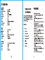
SPECIFICATIONS
A.Overall system
Oscillation mode:
Carrier Frequency Range:
Stability:
Max Deviation:
Dynamic Range:
S/N Ratio:
T.H.D:
Squelch:
Frequency Response:
Operating range:
B. Receiver
Sensitivity:
Image Rejection:
Stability:
Audio output:
Power supply:
Dimensions:
C. Transmitter
Mike capsule:
Antenna:
RF Output:
Spurious:
Battery:
Quartz controlled
VHF 169-270MHz
+0.005%
+ 56KHz with level limiting
>100dB
=80dB
<0.5%
"Pilotone & Noise lock" dual squelch circuit
100Hz-15KHz
Up to 240 Feet
6dB u V at S/N>90dB
>60dB
>80dB
-12db/600ohms unbalanced and balanced
15VDC/0.5A
16.5x8.2x 1.8 inch
Condenser Microphone(Headset mic/clip-on mic)
External
<1 0mW
<-40dB
one 9V battery
VHF WIRELESS SYSTEM
OPERATION MANUAL
Thank you for buying the PDWM4400 Wireless System. Please
read through these operation instructions so you will know how
to operate your model properly. After you read it, put it away in a
safe place for future reference.
CONTENTS
PI Precautions
Po System diagram
P3 Bodypack transmitter
PH Receiver Front panel
PS Receiver Rear Panel
Po Installation
P7 Trouble shooting
PS Specifications
PRECAUTIONS
*
*
*
*
*
*
*
*
*
*
Avoid exposure of the system to rain or moisture.
No user-serviceable parts inside the system. Refer all servicing to a qualified
technician only.
Handle the wireless system carefully, dropping or other shocks may cause
failure.
Avoid using the system where it may be subjected to heat, such as direct sunlight,
near radiators or other heat sources.
Should any liquid be spilt on the system, stop using it immediately. It may be
possible to dry the system, but you should have it checked by a qualified technician
before using it again.
Take care with the main power adapter and lead. If damaged in any way, do not use
the system and refer to a qualified technician for repair.
Only use the system with the supplied components. Do not attempt to use with any
other main power supply adapter .
If the wireless system is not going to be used for a while, remove the battery to
prevent leakage. In the event of electrolyte leakage inside the battery compartment,
carefully remove the leakage with a damp cloth. Take care not to get battery
electrolyte in contact with your skin, however if it does, wash your hands under a
running tap. If electrolyte comes into contact with your eyes, seek medical advice
immediately.
Only replace the battery with the same or an equivalent type.
Please dispose of old batteries in an environmentally friendly manner in accordance
with the relevant legislation.
Do not use any solvents to clean any part of the wireless system .
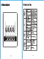
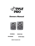
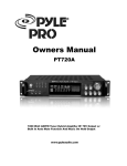
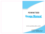
SYSIreM DIAGRAM
7
с Y
epee"
o o Sm PDWM4400 VHF PROFESSIONAL FOUR CHANNEL WIRELESS MICROPHONE SYSTEM
VOLUME VOLUME VOLUME VOLUME —
[|] o 0000 00000 00000 o 00000
RF AF LEVEL AF LEVEL AFLEVEL RF AF LEVEL
CHANNEL 1 CHANNEL 2 CHANNEL 3 CHANNEL 4
Oo POWER
TROUBLE SHOOTING
The wireless microphone is not
turned on.
Turn on the wireless microphone
The on air The microphone receiver is not | Turn on the microphone receiver
ме У turned on. and the connected audio equipment
The microphone receiver is not Turn on the microphone receiver
connected properly. and the connected audio equipment
The battery in the wireless
microphone is weak. Replace the battery.
The microphone receiver is not Turn on the microphone receiver
N q turned on. and the connected audio equipment.
o soun
The connected audio equipment is
not turned on.
Turn on the audio equipment.
The speakers/headphones. are not
connected to the audio equipment.
Connect the speakers/
headphones
The sound is
distorted
The battery in the wireless
microphone is weak.
Replace the battery.
The AUDIO OUT on the receiver
is not set correctly.
Adjust the volume controls.
A howling noise
heard from the
speakers.
The distance between the wireless
microphone and speakers are too
close.
Move the wireless microphone
away from the speakers or
change the direction of the
microphone.
The battery in the wireless
microphone is weak
Replace the battery.
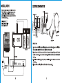
INSTALLATION
Using the supplied audio cable, connect from the MIXED jack socket to the
"MIC IN" / "LINE IN" socket on amplifier. Alternatively, you can connect an
optional XLR cable from the "XLR MIXED" socket on the receiver to a
professional mixer. Connect the mains power adaptor from "DC 15V" jack to
a suitable mains power socket.
Installation Location:
At least 3 ft. above ground level
At Least 3 ft. away from wall
AMPLIFIER
PROFESSIONAL MIXER
| RECEIVER
©
:
©
SPEAKERS
— ©boooo
CH-1 CH-2 CH-3 CH-4
XLR eo MIXED
DC IN
15V/500mA
O O O O
sas sas 502 sa oc
— MAINS POWER J
ADAPTER
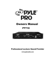
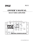
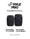
BODYPACK TRANSMITTER
BELT CLIP
BATTERY COVER
AUDIO OUTPUT JACK
VOLUME SWITCH
1 N
AUDIO SWITCH POWER SWITCH
LOW BAT
O ON [MUTE -20dB | 0dB OFF | ON
ON ©
MIC/LINE AUDJÖ POWER ATTENUATION POWER
/
LOW BATTERY LED
POWER LED
OPERATION
>
o
“ANTENNA
HEADSET MIC
LAVALIER MIC
1. Open the battery cover to install a 9V battery (check polarities). Move the power switch to the ON position. The power indicator will be green to
indicate normal operation. If the LOW BAT indicator turns red, replace with a fresh battery promptly.
2. Before operation, please confirm that the frequency of transmitter is same as the frequency of receiver. Plug the 3.5mm connector of headset mic
to screw-lock socket of transmitter. Move the audio switch to ON position. The MUTE switch cuts off the audio output without shutting off the
transmitter.
3. ATTENUATION is for volume adjustment. Move it to OdB position to get normal volume output. Move it to -20dB position to reduce distortion and
avoid feedback.
4. If the system will not be used for a long time, please switch off the transmitter to avoid power consumption.
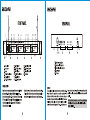
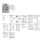
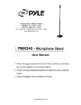
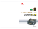
RECEIVER
Q
FRONT PANEL
3 3
DA N
1 4 5 6 7 8 9 10 11
NE —
O > ÉLEVLF PDWM{400 VHF PROFESSIONAL FOUR CHANNEL WIRELESS MIGROPHONE SYSTEM O
5 VOLUME VOLUME VOLUME | VOLUME 5
D 00000 à ©0000 d ©0000 ©0000
RF AF LEVEL RF AF LEVEL RF AF LEVEL RF AF LEVEL
|| (3 CHANNEL 1 CHANNEL 2 CHANNEL 3 | CHANNEL 4
ED /POWER ED
| 2 \ / — \
16 12 13 14 15 16
1. Power Indicator
2. Power Switch
3. Antenna
4. CH-1 RF Signal Indicator
5. CH-1 AF Indicator
6. CH-2 RF Signal Indicator
7. CH-2 AF Indicator
8. CH-3 RF Signal Indicator
9. CH-3 AF Indicator
10. CH-4 RF Signal Indicator
11. CH-4 AF Indicator
12. CH-1 Volume Control
OPERATION
Attach the two antennas and extend them vertically. Switch
on thereceiver. The red power indicator will come on.
Switch on the transmitter. Thered indicator RF/Channel1,
RF/Channel2, RF/Channel3, RF/Channel4 will come on to
indicate signal reception. The green AF LEVEL meters
indicate the audio level.
13. CH-2 Volume Control
14. CH-3 Volume Control
15. CH-4 Volume Control
16. Rack Mounts
Adjust the volume ofreceiver, transmitters and amplifier.
Please switch off the receiver, transmitters and amplifier
when the wireless microphone system is not being used.
RECEIVER
REAR PANEL
Jo 0000 ооо
MIXED
XLR MIXED
|
CH-1
CH-2
CH-3 CH-4
LJ
17 18
—
19 20 21
180
17.Mixed balanced output jack
18.Mixed unbalanced output jack
19.Individual unbalanced output jack
20.Squelch adjustor
21.DC Power in
SQUELCH
The squelch control on the rear of the receiver is preset at the factory.
If you must use the system in an area with considerable RF
interference and there is some noise from the receiver when your
transmitter is off, you can adjust the squelch control so that the system
will receive the signal from your transmitter only but squelch or
eliminate the unwanted background RF noise. This adjustment can
cause reduction in useable range of the wireless transmitter, so set the
control to the lowest position that reliablely mutes the unwanted RF
signals.
Note that switching the microphone on and off can cause interference
that will be heard if the microphone volume level of the amplifier
system is still set high.
5