1
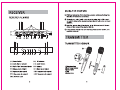
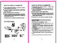
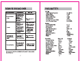
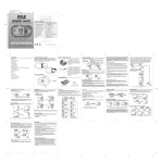
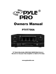
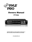
 PDWM7300
Usage Manual
www.pyleaudio.com
CONTENTS
CONTENTS 0000 0000 00000!
GENERAL DESCRIPTION 000000000 000000000000000000000007
FEATURES 000 0 00 00 000 00000 00000000000000000000000000007
ILLUSTRATION OF RECEIVER
RCEIVER REMARK e occcoocoacococooCOCOCOCOCOOCACACAC ©
USING THE RECEIVER 000000000000000000000000000000004
ILLUSTRATION OF TRANSMITTER
HANDHELD TRANSMITTER REMARK e¢eccccccccccccccccce]
USING THE HANDHELD TRANSMITTER eccccccccccscccccseh
BODYPACK TRANSMITTER REMARK e¢ccccccccccccccccccse
USING THE BODYPACK TRANSMITTER esccccacacacacacece.
CAUTIONT:0 0 00 050 000 0 0 2000 0 0 00 000000000000000000000000000
REMOVE BREAKDOWN 00 00 000000000000 000000000000000008
PARAMETER 00 0080 000 0080 0000000000000 000000 00000000000000 0028
ON © © ©
INTRODUCTION
Thank you for purchasing our product.We will feed back customers high
quality product. Anyway, welcome to suggest us good idea,so that our pro-
ducts will get better and better.
This type of wireless microphone system is using for UHF band rec-
eiver, Itisnotonly widely used in various of performance stage
but also assembly hall and entertainment place like karaoke hall. The
novelty, high quality and stability product made our product gains the
reputations among our customers all over the world. On the other hand,
our product can be used with handheld and the lapel at the same time,
that is very free.
Please read this specification carefully, that you can operate it corre-
ctly, and you can use this unit fora long time. Please keep it well.
It is for future reference.
FEATURES
) UHF 500MHz used for Frequency of Carrier Wave,low interference.
XX Volume can be controlled by the column fixed on the receiver.Radio la-
mp and audio lamp used to clarify the condition.
¥ One receiver accompanies with four wireless microphones.
x Audio-Expand&Compress technic used to perfect the timbre.
XX Codistor fixed inside to avoid large noise caused by wireless mic-
rophone interfering.
¥K Convenient antenna fixed inside of the wireless microphone.
¥K Balanceable and lopsided audio output, separate and mixed output is
useful for family and other situations.
2
RECEIVER
RECEIVER REMARK
000
соо
go
> Di
9 $,
+,
4 \s
x “
в "
я a
* A:
+ о
oN A
- +
—
oT
> Be,
+, 3,
+,
6 NE
a .
x LI
a I
* 2 00
LA A
> Ad
= +
70 Ds. ВНЕ >
DOE Quer
> й |_CHAIINEL.4 ©
429 4029 929 @ 29 Q
0099 D 4
She b 66
o
у
@—-—e-
O——e—=
@—O
@—
(1) Power Switch (2) RFIndicator
( 3) Audio Signal Indicator (4) Audio Volume
(5) Digita Tube Frequency Display (6) Antenna
( 7 ) Balance Audio Output (8) Mixed Audio Output
(9) Separated mic output! (10) Separated mic output?
(11) Separated mic output3 (12) Separated mic output4
(13) AC Power Jack
USING THE RECEIVER
@ Pull four antennas of the machine, please notice pull along the
direction of antennas connector.
@) Connectone endofaudio cable to audio output jack of the recei-
ver and the other end to microph one input jack of audio mixer or power
amplifier.
© Input the output plug of the adaptor tothe DC input port of the rec-
eiver, and then connect the adaptor with AC.
@ If the power supply has connected, press power switch, the
machine turns on.
TRANSMITTER
TRANSMITTER REMARK
(1)Microphone Head
(2)Low Voltage Indicator
(3)power switch
(4)Grip
(5)Battery Cover
USING THE HANDHELD TRANSMITTER
(1) Open the handheld microphone battery cover and putin two AA batteries
in right polarity then close battery cover.
(2) Turn on the power switch of microphone and the power indicator will
be light soon, the transmitter send the signal to the receiver, and the
RF indicator is light now.
(8) When the transmitter is not used, turn the power off.
(4) When the low voltage indicator lights ,it means the power of the battery is
not enough.Ifit has affected using effect(The distance between the re-
ceiver and transmitter is not far enough or the voice is distortion), you
had batter replace a new battery.
If the unit does not use for along time ‚you must take out the battery.
BODYPACK REMARK
I
(1)Microphone Jack (2)Low Voltage Indicator (3)Power Switch
(4)Audio Volume (5)Microphone Head (6)Clip
(7)Microphone Wire (8)Microphone Jack (9)Belt Clip
(10)Battery Cover
USING THE BODYPACK TRANSMITTER
(1) Open the microphone battery coverand putin a 9V battery in right
polarity then close battery cover.
@) Turn onthe powerswitch of microphone and the power indicator will
be light soon , the transmitter send the signal to the receiver and
the RF indicator is light now.
@ When the transmitter is not used, turn the power off.
@ When the low voltage indicator lights, it means the power of the battery
is not enough. Ifit has affected using effect (The distance between the
receiver and transmitter is not farenough,or the voice is distortion you
had batter replace a new battery.
® If the unit does not use for a long time ,you must take out the battery.
CAUTION
Read this before operating your unit:
Please read this manual carefully before using. And keep it in a safe
place for future reference.
2. Donotexpose the unit with rain or an environment where it may be
splashed by water or other liquids, as doing may result in fire or
electric shock.
3. Donotuse force on switches, knobs or cords. When moving the set
turn the unit off first.
4. Do not attempt to clean the unit with chemical solvents, this might
damage the surface, you should use the clean and dry cloth.
|
4
5. To prevent receiver damage , please cut off power during electrical st-
orms.
6. The voltage used must be the same as that specified on this unit.
REMOVE BREAKDOWN
BREAKDOWN
REASONS
SOLVE
The power indicator is
not light
1\The transmitter does
not load in the battery,
and the battery have
no power or change
thebattery.
2\The power jack of
receiver is not atta-
ched power.
1\Load in a new battery.
2\Turn on the power of
receiver.
No voice
1\The transmitter is not
turned on.
2\The AF cord of rece-
iver has not been
connected.
3\ The volume of the re-
ceiver or the loudsp-
eaker is too low.
4\The transmitter is far
from the receiver.
5\The frequency or rece-
iver is different from
transmitter.
1\Turn on the transmit-
ter.
2\Joint the receiver and
loud-speaker toge-
ther.
3\Turn up the volume.
4\Do not make the tra-
nsmitter far away
from the receiver.
5\Adjusting the same
frequency.
The distance betwe-
en the receiver and
transmitter is not far
enough
1\Do not draw out the
antenna fully.
2\The power of the b-
attery is not enough.
1 Draw out the antenna
fully.
2\Replace a new battery.
The voce is distortion
1\The powerof the batt-
ery is not enough.
2\The loud-speaker is
too near to the rec-
eiver.
1\Replace a new battery.
2\Put the loud-speaker
far from the receiver.
If do not use it well after checking the unit yourself, please contact
the professional.
PARAMETER
SYSTEM
Audio Frequency Response:
Dynamic Range:
System Distortion:
Signal-to-Noise Ratio:
Operating Range:
Operating Temperature Range:
Carrier Frequency Range:
Receiver:
Sensitivity (S/N=30dB)
Image Rejection:
De-Emphasis:
Audio Output Impedance:
Audio Output Level:
Power Supply:
Current Consumption:
Dimensions:
Weight:
Transmitter: Hand-held
Frequency Stability: +0.001
R F Output power: <30mW
Spurious Rejection: > 50dB
Modulation Mode: FM
Maimum Deviation Range: +45KF7
Microphone Mode: Dynamic
Pre-Emphasis: 5018
Power Supply: 1.5V Battery
Current Consumption: <40mA
Dimensions: $35x270mm
Weight: = 2500
8
80-12500Hz
=90dB
<1%
=90dB
~ 80M
50-457
480-550MHz
<4uB
>60dB
5015
600Q + 10%
11v
DC12V
< 300MA
480x220x45mm
=21700g
Bodypack
+0.001
<30mW
> 500В
ЕМ
+45KFz
Electric capality
50uS
9V Battery
<40mA
95x 60x 20mm
= 900