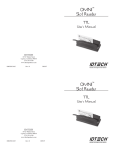
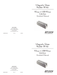
1
TM
New MINIMAG
Magnetic Stripe Reader
Port Powered
Quickstart Manual
ID TECH
10721 Walker Street
Cypress, California 90630
(714) 761-6368
www.idtechproducts.com
80066508-001
Rev. B R04/06
#418
AGENCY APPROVED
MESSAGE DATA FORMAT
Specifications for subpart B of part 15 of FCC rule for a Class A computing
device.
<SS1><DATA1><ES><SS2><DATA2><ES><SS3><DATA3>
<ES><CR>
LIMITED WARRANTY
ID TECH warrants to the original purchaser for a period of 24 months from
the date of invoice that this product is in good working order and free from
defects in material and workmanship under normal use and service. ID
TECH’s obligation under this warranty is limited to, at its option, replacing,
repairing, or giving credit for any product which has, within the warranty
period, been returned to the factory of origin, transportation charges and
insurance prepaid, and which is, after examination, disclosed to ID TECH’s
satisfaction to be thus defective. The expense of removal and reinstallation of any item or items of equipment is not included in this warranty. No
person, firm, or corporation is authorized to assume for ID TECH any other
liabilities in connection with the sales of any product. In no event shall ID
TECH be liable for any special, incidental or consequential damages to Purchaser or any third party caused by any defective item of equipment, whether
that defect is warranted against or not. Purchaser’s sole and exclusive
remedy for defective equipment, which does not conform to the requirements
of sales, is to have such equipment replaced or repaired by ID TECH. For
limited warranty service during the warranty period, please contact ID TECH
to obtain a Return Material Authorization (RMA) number & instructions for
returning the product.
Where <SS1>, <SS2>, and <SS3> are start sentinels for Track 1,
Track 2, and Track 3, and <ES> is the end sentinel for all tracks.
ISO format:
<SS1> is %
<SS3> is +
<SS2> is ;
<ES> is ?
CADMV format:
<SS1> is %
<SS3> is !
<SS2> is ;
<ES> is ?
<DATAX> is the decoded data for Track X. It is the character
“E” if the magnetic data on Track X is not valid.
THIS WARRANTY IS IN LIEU OF ALL OTHER WARRANTIES OF
MERCHANTABILITY OR FITNESS FOR PARTICULAR PURPOSE.
THERE ARE NO OTHER WARRANTIES OR GUARANTEES, EXPRESS
OR IMPLIED, OTHER THAN THOSE HEREIN STATED. THIS PRODUCT IS SOLD AS IS. IN NO EVENT SHALL ID TECH BE LIABLE FOR
CLAIMS BASED UPON BREACH OF EXPRESS OR IMPLIED WARRANTY OF NEGLIGENCE OF ANY OTHER DAMAGES WHETHER DIRECT, IMMEDIATE, FORESEEABLE, CONSEQUENTIAL OR SPECIAL
OR FOR ANY EXPENSE INCURRED BY REASON OF THE USE OR
MISUSE, SALE OR FABRICATIONS OF PRODUCTS WHICH DO NOT
CONFORM TO THE TERMS AND CONDITIONS OF THE CONTRACT.
8
RS-232 PARAMETERS
Baud Rate
Data Bits
Parity
Stop Bits
Hand-Shaking
9600
8
None
1
X-ON/X-OFF (11h/13h)
7
©2006 International Technologies & Systems Corporation. The information
contained herein is provided to the user as a convenience. While every effort
has been made to ensure accuracy, ID TECH is not responsible for damages
that might occur because of errors or omissions, including any loss of profit
or other commercial damage. The specifications described herein were current at the time of publication, but are subject to change at any time without
prior notice.
ID TECH is a registered trademark of International Technologies & Systems
Corporation. MiniMag and Value through Innovation are trademarks of
International Technologies & Systems Corporation.
SPECIFICATIONS
TROUBLE SHOOTING PROCEDURES
Power Requirements:
5 to 12 VDC/7mA.
Operating Current:
5 mA typical (including LED)<9mA peak (<1ms).
The troubleshooting process can be simplified by reviewing
these reader operations.
Operating
Temperature:
32° F to 131° F (0° C to 55° C).
Storage Temperature:
-22° F to 158° F (-30° C to 70° C).
Relative Humidity:
10% to 90% non-condensing.
Magnetic Head Life:
1,000,000 passes minimum.
Rail and Cover Life:
1,000,000 passes minimum.
Magnetic Stripe
Encoding & Formats:
Two-frequency coherent phase (F2F) compatible
with ISO 7811 ANSI, AAMVA, and California DMV.
Once the unit has indicated a “good read,” then proceed to check
the interface configuration.
Installation of the reader is generally easy and trouble free, here
are some considerations if problems occur.
Does the host COM port baud rate, number of data bits &
parity match the reader? See RS232 Parameters.
Maximum Number
of Tracks:
3 tracks.
Swipe Speed:
3 to 60 inches per second, bidirectional.
Card Thickness:
.015 to .045 inches.
Dimensions: Length:
Once it has been confirmed that the unit is correctly powered,
swipe a credit card. The LED will go off while decoding, then
light green to indicate a “good read,” or red to indicate a “bad
read.”
Is the host set-up for card reader operation and is the card
reader application running? Check the application set-up
parameters.
3.56 inches (90mm). Width: 1.34 inches
(34mm). Height: 1.10 inches (28mm).
Weight:
5.5 oz. (with cable).
Cable Length:
6-foot straight cable.
1
Does the configuration of the reader’s magnetic stripe data
output match the host application data input requirements?
The application may need to be configured to match.
6
OPERATION
DESCRIPTION
1. Connect the MiniMag reader cable to the 9-pin male serial
port on a computer. Insure the reader cable connector is fully
seated with the computer.
The MiniMag™ compact magnetic stripe reader can read 1, 2,
or 3 tracks of magnetic stripe information. Power consumption
is low; standard RS-232 ports can power it. Operating current is
less than 9mA maximum for a 3-track configuration.
2. Run an RS-232 communication program (such as HyperTerminal). Select the serial port to which the reader cable has been
connected. The application needs to open the RS-232 port with
DSR set to HIGH. (A typical communication program sets DSR
to HIGH by default.)
3. The green LED will light to indicate the reader is powered.
4. Set the baud rate at 9600, 8 data bits, 1 stop bit, and no parity.
5. The LED is normally GREEN (reader ready). Slide a card, in
either direction, through the reader slot, with the magnetic stripe
facing the magnetic head (opposite the LED side of the reader).
6. The LED will be off during a card read swipe. The GREEN
LED will be on after a good read operation; otherwise, the LED
will be RED for 1/2 second, then return to GREEN.
The decoding electronics are based on MagChip ASIC technology designed for use with magnetic stripe cards encoded with F2F
ANSI and ISO-conforming data. The MiniMag reliably decodes
data encoded within ANSI and ISO standards, on both high and
low coercivity magnetic media. The circuit is designed to read
cards demagnetized down to 30% or 40% of ISO and ANSI signal levels, on Track 1 and Track 3 or Track 2 respectively. These
reading characteristics are designed to insure that the MiniMag
will reliably read ‘real world’ cards.
In order to insure reliable reading under varying conditions, the
MiniMag will read magnetic media at speeds from 3 inches per
second (IPS) to 60 IPS with typical accelerations. The output is
standard RS-232.
7. The data on the card will be shown on the screen. Check the
communication parameters if the data on the screen is not correct.
NOTE: Sending data to the reader while swiping a card will
cause a bad read.
5
2
HOST CONNECTIONS
POWER-ON INITIALIZATION
The Port-Powered MiniMag reader is connected to a 9-pin male
serial port on a host (such as a PC) using a DB9 female connector. Pinout designations are as follows:
The MiniMag will always transmit an identification string within
2 seconds after it powers up. The identification string has the
following format:
PIN
SIGNAL
<compressed part number><revision information>
2
3
4
5
TXD
RXD
DSR
GND
The <compressed part number> is eight characters and the
<revision information> is three characters.
(Supply Voltage in)
SLEEP & WAKE-UP
The reader uses a sleep mode to save power when not in use.
The reader wakes-up when a card is swiped. After the card data
is transmitted the reader returns to the sleep mode. The LED
will remain on to show the “ready to read” condition.
The reader also wakes-up 5ms after receiving a character from
the RS232 port. The reader will stay awake for about 100ms to
receive any commands from the host. The reader returns to sleep
mode after commands are processed.
3
4