1
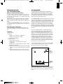
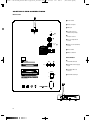
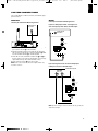
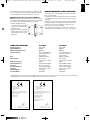
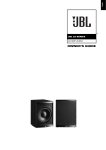
30/07/08
6:47
Side 1
(Sort/Black plade)
English
0048CSK - JBL ES150PW_ES250PW ENG v2.qxp:33346_JBL ES150_250_ENG
®
ES SERIES
ES150PW, ES250PW (230V)
OWNER’S GUIDE
0048CSK - JBL ES150PW_ES250PW ENG v2.qxp:33346_JBL ES150_250_ENG
30/07/08
6:47
Side 2
(Sort/Black plade)
IMPORTANT SAFETY INSTRUCTIONS
1. Read these instructions.
2. Keep these instructions.
3. Heed all warnings.
4. Follow all instructions.
5. Do not use this apparatus near water.
6. Clean only with a dry cloth.
7. Do not block any ventilation openings. Install in accordance with
the manufacturer’s instructions.
8. Do not install near any heat sources such as radiators, heat
registers, stoves or other apparatus (including amplifiers) that
produce heat.
9. Do not defeat the safety purpose of the polarized or groundingtype plug. A polarized plug has two blades with one wider than the
other. A grounding-type plug has two blades and a third grounding
prong. The wide blade or the third prong is provided for your safety.
If the provided plug does not fit into your outlet, consult an
electrician for replacement of the obsolete outlet.
10. Protect the power cord from being walked on or pinched,
particularly at plugs, convenience receptacles and the point where
they exit from the apparatus.
11. Only use attachments/accessories specified by the
manufacturer.
12. Use only with the cart, stand, tripod, bracket or
table specified by the manufacturer or sold with the
apparatus. When a cart is used, use caution when
moving the cart/apparatus combination to avoid injury
from tip-over.
13. Unplug this apparatus during lightning storms or when unused for
long periods of time.
2
14. Refer all servicing to qualified service personnel. Servicing is
required when the apparatus has been damaged in any way, such as
power supply cord or plug is damaged, liquid has been spilled or
objects have fallen into the apparatus, or the apparatus has been
exposed to rain or moisture, does not operate normally or has been
dropped.
15. Do not expose this apparatus to dripping or splashing and ensure
that no objects filled with liquids, such as vases, are placed on the
apparatus.
16. To completely disconnect this apparatus from the AC Mains,
disconnect the power supply cord plug from the AC receptacle.
17. The mains plug of the power supply cord shall remain readily
operable.
18. Do not expose batteries to excessive heat such as sunshine, fire
or the like.
The lightning flash with arrowhead symbol, within
an equilateral triangle, is intended to alert the
user to the presence of uninsulated “dangerous
voltage” within the product’s enclosure that may
be of sufficient magnitude to constitute a risk of electric shock to
persons.
The exclamation point within an equilateral triangle is
intended to alert the user to the presence of important
operating and maintenance (servicing) instructions in
the literature accompanying the product.
WARNING: To reduce the risk of fire or electric shock, do not expose
this apparatus to rain or moisture.
30/07/08
6:47
Side 3
(Sort/Black plade)
English
0048CSK - JBL ES150PW_ES250PW ENG v2.qxp:33346_JBL ES150_250_ENG
INTRODUCTION
PLACEMENT
JBL® ES150PW/ES250PW
Wireless Powered Subwoofers
Since the installation of a subwoofer can be somewhat more
complicated than installation of full-range speakers, it is essential
that you read this section very carefully prior to connecting the
subwoofer to your system. Should you have questions relating to
your installation, it is advisable to contact either your dealer or the
JBL Customer Service Department for advice.
For more than 60 years, JBL audio equipment has been used in concert halls, recording studios and movie theaters around the world,
and has become the hands-down choice of leading recording artists
and sound engineers.
With the JBL ES Series, innovative technologies such as titaniumlaminate-dome tweeters, Elliptical Oblate Spheroidal™ (EOS) waveguides and PolyPlas™ transducer reinforcement are available to you.
Enjoy!
In addition, the ES150PW/ES250PW’s compact enclosure and wireless capability allow for easy integration into any residential environment. Enjoy!
Unpacking the Subwoofer
If you suspect damage from transit, report it immediately to your
dealer. Keep the shipping carton and packing materials for future
use.
Included
1 x Owner’s manual
1 x Subwoofer
1 x 230V AC cord for subwoofer – SCHUKO plug
1 x 230V AC cord for subwoofer – UK plug
1 x 5m Audio cable, RCA-RCA
1 x Transmitter module
1 x Power supply for transmitter
1 x 230V AC power cord for transmitter power supply –
SCHUKO plug
1 x 230V AC power cord for transmitter power supply – UK plug
1 x 2m Audio cable, RCA-RCA
1 x Wall-mount bracket for transmitter (with two pan-head M3 x
4 machine screws for attaching wall-mount bracket to transmitter)
4 x Small, round, self-adhesive feet – to be attached on transmitter’s left side panel if transmitter is to be used vertically
The ES150PW/ES250PW’s wireless capability makes it even easier to
properly locate the subwoofer in your room. The performance of the
subwoofer is directly related to its placement in the listening room
and how you align the subwoofer with its satellite speakers. Setting
the volume of the subwoofer in relationship to the left and right
speakers is also of critical importance because it is essential that
the subwoofer integrate smoothly with the entire system. Setting the
subwoofer’s volume level too high will result in overpowering, boomy
bass. Setting the volume level too low will negate the benefits of the
subwoofer.
Here are several additional facts on installation that may prove
useful. It is generally believed by most audio authorities that low
frequencies (below 125Hz) are nondirectional and, therefore,
placement of a subwoofer within any listening room is not critical.
While in theory it is true that the larger wavelengths of extremely
low frequencies are basically nondirectional, the fact is that, when
installing a subwoofer within the limited confines of a room,
reflections, standing waves and absorptions generated within the
room will strongly influence the performance of any subwoofer
system. As a result, specific location of the subwoofer becomes
important, and we strongly recommend that you experiment with
placement before choosing a final location.
Placement will depend upon your room and the amount and quality
of bass required (for example, whether or not your room permits
placement of the subwoofer near either satellite).
SUB
RIGHT
CHANNEL
SPEAKER
PRIMARY
LISTENING
AREA
Figure 1. This example shows the subwoofer positioned behind the
right-channel satellite speaker to re-create the actual location of
bass instruments in an orchestra and/or add impact to movie soundtracks.
3
0048CSK - JBL ES150PW_ES250PW ENG v2.qxp:33346_JBL ES150_250_ENG
30/07/08
6:47
Side 4
(Sort/Black plade)
CONTROLS AND CONNECTIONS
Rear Panel
0 Power Switch
1 Line-Level Inputs
2 LFE Input
3 Low-Pass Selector
(Wireless Input Only)
Phase
Antenna
•
ª
4 ID-Code Selector
Level
¶
Crossover
[Hz]
∞
5 Crossover Adjustment
Control
§
6 Subwoofer-Level (Volume)
Control
Wireless
Off
ID Code
7 Phase Switch
On
Low-Pass
8 Wireless Antenna
¢
Transmitter
™
9 Transmitter Antenna
£
R
L
LFE
A Transmitter Power-Supply
Input
Sub In
B Transmitter ID-Code
Selector
Power
On
C Transmitter Sub Input
¡
Off
ID
CODE
DC18V
‚
4
⁄
1234
Sub In
‹
30/07/08
6:47
Side 5
(Sort/Black plade)
English
0048CSK - JBL ES150PW_ES250PW ENG v2.qxp:33346_JBL ES150_250_ENG
SYSTEM CONNECTIONS
Choose either Wireless or Wired connection, then follow the appropriate instructions.
WIRELESS
Connecting the Subwoofer for Wireless Applications
SUBWOOFER OR
LFE OUTPUT
WIRED
Connecting the Subwoofer for Wired Applications
If you have a Dolby® Digital or DTS® receiver/processor
with a low-frequency-effects (LFE) or subwoofer output:
SUBWOOFER OR
LFE OUTPUT
Level
ID
CODE
DC18V
1234
Crossover
[Hz]
Sub In
1. Connect a subwoofer cable from the subwoofer or LFE output of
your receiver to the Sub C on the transmitter.
2. Plug the transmitter module’s power supply into the wall outlet,
and connect the included power cord to the transmitter A. Make
sure the Transmitter Antenna 9 is extended upward.
3. Set the ID code on the transmitter and subwoofer (B and 4) to
the same position, as described on page 6. When connected properly, the LED on the top of the subwoofer will be orange.
4. Set the Low-Pass Selector 3 to the “Off” position.
NOTE: Some receivers have two subwoofer outputs. In that case,
use either connector.
Wireless
O
Offff
ID Code
OOnn
Low-Pass
Low-Pass
L
Sub In
R
LFE
Line In
If your receiver/processor does not contain a Dolby Digital
or DTS processor, but has subwoofer outputs:
RECEIVER/PROCESSOR
Level
Crossover
[Hz]
Wireless
Off
ID Code
On
Low-Pass
L
Sub In
R
LFE
Line In
NOTE: If your receiver/processor has only one sub out, you may use
either the L or R input.
5
0048CSK - JBL ES150PW_ES250PW ENG v2.qxp:33346_JBL ES150_250_ENG
OPERATION
30/07/08
6:47
Side 6
(Sort/Black plade)
the same channel. Once you have a green or orange LED on the subwoofer, turn your Subwoofer-Level Control 6 up halfway so that the
knob indicator points up. You should now be hearing bass information coming from the subwoofer.
Power On
Connect your signal source (such as an A/V receiver or preamplifier)
to the transmitter (if using a wireless connection) or to the subwoofer (if using a wired connection). Two single-RCA cords are provided. While you would ordinarily use the short cable to connect to
the transmitter or the long one to connect to the subwoofer, either
cable can be used, depending on proximity to the signal source.
There is no need or benefit gained from connecting the same source
to both the transmitter and the subwoofer. However, you could connect two separate sources to the subwoofer by utilizing both its
wired and wireless connections. Both signals will essentially be
mixed and outputted by the subwoofer. Plug your transmitter’s (if
using a wireless connection) and subwoofer’s AC cord into a wall
outlet. Do not use the outlets on the back of the receiver for the subwoofer.
Initially set the Subwoofer-Level Control 6 to the “min” position.
Turn on your sub by pressing the Power Switch 0 on the rear panel.
Turn on your entire audio system and start a CD or movie soundtrack
at a moderate level.
Adjust Level
Set the overall volume control of the preamplifier or stereo to a
comfortable level. Adjust the Subwoofer-Level Control 6 until you
obtain a pleasing blend of bass. Bass response should not overpower the room but rather be adjusted so there is a harmonious
blend across the entire musical range. Many users have a tendency
to set the subwoofer volume too loud, adhering to the belief that a
subwoofer is there to produce lots of bass. This is not entirely true.
A subwoofer is there to enhance bass, extending the response of the
entire system so the bass can be felt as well as heard. However,
overall balance must be maintained or the music will not sound
natural. An experienced listener will set the volume of the subwoofer
so its impact on bass response is always there but never obtrusive.
Auto On/Standby
Transmitter (Wireless Connection Only): The Status LED (not
shown) will be lit in red when the unit is in Standby. When the transmitter receives an audio signal from the source, it will immediately
turn on and the LED will turn to blinking green or solid green:
RED = STANDBY (No signal detected, transmitter off)
GREEN (BLINKING) = Transmitter is on but has not established a link
with the wireless sub
GREEN (SOLID) = Transmitter is on and has already established a link
with the wireless sub
The transmitter will automatically enter Standby mode after approximately 10 minutes when no signal is detected from your system.
Subwoofer: With the Power Switch 0 in the ON position, the Status
LED on the top will remain lit to indicate the On/Standby mode of the
subwoofer.
RED = STANDBY (No signal detected, Amp Off)
GREEN = SUB ON (Wired signal detected, Amp On)
ORANGE = SUB ON (Wireless link with transmitter active)
The subwoofer will automatically enter the Standby mode after
approximately 10 minutes when no signal is detected from your
system. The subwoofer will then power ON instantly when a signal is
detected. During periods of normal use, the Power Switch 0 can be
left on. You may turn off the Power Switch 0 for extended periods
of nonoperation, e.g., when you are away on vacation.
Crossover Adjustment
The Crossover Adjustment Control 5 determines the highest
frequency at which the subwoofer reproduces sounds. If your main
speakers can comfortably reproduce some low-frequency sounds,
set this control to a lower frequency setting, between 50Hz and
100Hz. This will concentrate the subwoofer’s efforts on the ultradeep
bass sounds required by today’s films and music.
If you are using smaller bookshelf speakers that do not extend to the
lower bass frequencies, set the Crossover Adjustment control to a
higher setting, between 120Hz and 150Hz.
NOTE: This control will have no effect if the LFE Input 2 is used
(wired connection) or if the Low-Pass Selector 3 is in the “OFF”
position (wireless connection). If you have a Dolby Digital or DTS
processor/receiver, the Low-Pass Frequency is set by the processor/receiver. Consult your owner’s manual to learn how to view or
change this setting.
Getting Started
Confirm that the Status LED on the transmitter is on (red or green),
the Status LED on the subwoofer is on (red, orange or green) and an
RCA cable is connected from a source unit to either the LFE Input of
the subwoofer 2 or transmitter C or L and R inputs 1 on the subwoofer. Play a CD or video. Use a selection that has ample bass
information. If using a wireless connection, the Status LED on the
transmitter should be lit in solid green, and the Status LED on the
subwoofer should turn orange if connected wirelessly. If the LED on
the transmitter is blinking in green and the LED on the subwoofer is
in red or green, a wireless link has not been established between the
transmitter and the subwoofer. If connecting directly to the subwoofer without using the wireless link, the Status LED on the subwoofer should be lit green. If the LED on the subwoofer remains red,
check that the RCA cable from the source to subwoofer (wired connection) or transmitter (wireless connection) is functioning properly
and that it is fully inserted at both ends, or that the Transmitter IDCode Selector B and the Subwoofer ID-Code Selector 4 are set to
6
Phase Control
The Phase Switch 7 determines whether the subwoofer speaker’s
pistonlike action moves in and out with the main speakers, 0˚, or
opposite the main speakers, 180˚. Proper phase adjustment depends
on several variables such as room size, subwoofer placement and
listener position. Adjust the phase switch to maximize bass output at
the listening position.
ID Codes
In the unlikely event that you experience interference when operating the system, or if you have more than one set of subwoofer transmitters and receivers in operation, you may change the channel in
which the system operates. On the transmitter module and the subwoofer, there is a four-position ID-Code Selector (B and 4). Simply
set the selectors to one of the other positions. The transmitter and
subwoofer (B and 4) selectors must be set to the same position
for the system to function correctly. You can also set up a maximum
of two subwoofers to be receiving from the same transmitter by setting the channel selector on the transmitter and both of the subwoofers to the same channel.
A Word About Wireless Products
The JBL ES150PW and ES250PW wireless subwoofers utilize
advanced wireless transceivers operating in the 2.4GHz frequency
band. This is the same frequency band that is used for wireless
home networks and high-quality cordless phones.It also allows for
the transmission of high-performance, full-spectrum sound to
remote locations, wirelessly.
Like all wireless devices, the JBL wireless subwoofer’s operating
range may vary, depending upon variables such as building con-
30/07/08
6:47
Side 7
(Sort/Black plade)
English
0048CSK - JBL ES150PW_ES250PW ENG v2.qxp:33346_JBL ES150_250_ENG
struction methods and materials, atmospheric conditions and other
sources of interference. Please consult your JBL dealer or distributor, or visit www.jbl.com, for further information or assistance.
Wall-Mounting the Transmitter Module
NOTE: The customer is responsible for the correct selection and use
of mounting hardware (available through hardware stores) that will
ensure the proper and safe wall-mounting of the transmitter.
1. Insert the two M3 x 4 machine
screws through the wall bracket
and into the rear of the transmitter
module, as shown.
2. Attach the transmitter module with
wall bracket to the wall, using suitable hardware and, if necessary,
wall anchors.
MAINTENANCE AND SERVICE
The enclosure may be cleaned using a soft cloth to remove fingerprints or to wipe off dust.
The grille may be gently vacuumed. Stains may be removed with an
aerosol cleaner, following its instructions. Do not use any solvents
on the grille.
All wiring connections should be inspected and cleaned or remade
periodically. The frequency of maintenance depends on the metals
involved in the connections, atmospheric conditions and other
factors, but once per year is the minimum.
In the event that your subwoofer ever needs service, contact your
local JBL dealer, or visit www.jbl.com for a service center near you.
SPECIFICATIONS
ES150PW
ES250PW
Frequency Response
Amplifier RMS Power
Amplifier Peak Dynamic Power†
Crossover Frequency
27Hz – 150Hz
300 Watts
500 Watts
50Hz – 150Hz; 24dB/octave
continuously ajustable
when activated
250mm (10") PolyPlas™
Up to 22m (75'),
depending upon conditions
2.4GHz
457mm x 337mm x 409mm
(18" x 13-1/4" x 16-1/8")
95mm x 124mm x 100mm
(3-3/4" x 4-7/8" x 3-15/16")
17.7kg (39 lb)
0.2kg (0.5 lb)
25Hz – 150Hz
400 Watts
700 Watts
50Hz – 150Hz; 24dB/octave
continuously ajustable
when activated
300mm (12") PolyPlas™
Up to 22m (75'),
depending upon conditions
2.4GHz
502mm x 400mm x 454mm
(19-3/4" x 15-3/4" x 17-7/8")
95mm x 124mm x 100mm
(3-3/4" x 4-7/8" x 3-15/16")
19.5kg (43 lb)
0.2kg (0.5 lb)
Driver
Operating Range
RF Operating Frequency
Subwoofer Dimensions
(H x W x D)
Transmitter Dimensions
(H x W x D)
Subwoofer Weight
Transmitter Weight
†
The Peak Dynamic Power is measured by recording the highest center-to-peak voltage measured across the output of a resistive load equal to
minimum impedance of the transducer, using a 50Hz sine wave burst, 3 cycles on, 17 cycles off.
Declaration of Conformity
Declaration of Conformity
We, Harman Consumer Group, Inc.
2, route de Tours
72500 Château du Loir
France
We, Harman Consumer Group, Inc.
2, route de Tours
72500 Château du Loir
France
declare in own responsibility that the product
declare in own responsibility that the product
described in this ownerʼs manual is in compliance
described in this ownerʼs manual is in compliance
with technical standards:
with technical standards:
EN 61000-6-3:2001
EN 55013:2001+A1:2003
EN 61000-6-1:2001
EN 55020:2002+A1:2003
EN 61000-3-2:2000
EN 61000-3-3:1995+A1:2001
EN 60065:2002
Laurent Rault
Harman Consumer Group, Inc.
Château du Loir, France 6/08
Laurent Rault
Harman Consumer Group, Inc.
Château du Loir, France 6/08
7
0048CSK - JBL ES150PW_ES250PW ENG v2.qxp:33346_JBL ES150_250_ENG
30/07/08
6:47
Features, specifications and appearance are subject to change without notice.
JBL is a trademark of Harman International Industries, Incorporated, registered
in the United States and/or other countries. Elliptical Oblate Spheroidal, PolyPlas and
Pro Sound Comes Home are trademarks of Harman International Industries, Incorporated.
Dolby is a registered trademark of Dolby Laboratories.
DTS is a registered trademark of DTS, Inc.
PRO SOUND COMES HOME™
®
Harman Consumer Group, Inc., 250 Crossways Park Drive, Woodbury, NY 11797 USA
www.jbl.com
© 2008 Harman International Industries, Incorporated. All rights reserved.
Part No. 406-000-05853-E
Side 8
(Sort/Black plade)