1
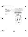
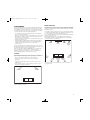
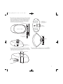
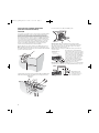
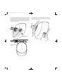
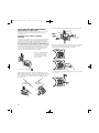
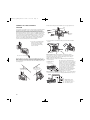
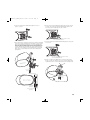
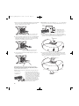
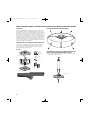
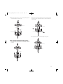
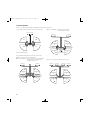
JBLP2605_CN_CNAW_PM-OM
4/23/08
12:57 PM
Page 1
®
JBL® CONTROL® SERIES
JBL CONTROL NOW™
JBL CONTROL NOW™ AW
OWNER’S GUIDE
JBLP2605_CN_CNAW_PM-OM
4/23/08
12:57 PM
Page 2
TABLE OF CONTENTS
UNPACKING THE SPEAKERS . . . . . . . . . . . . . . . . . . . . . . . . . . . . . 2
PLACEMENT. . . . . . . . . . . . . . . . . . . . . . . . . . . . . . . . . . . . . . . . . . . . 3
WALL SURFACE-MOUNTING . . . . . . . . . . . . . . . . . . . . . . . . . . . . . 4
WALL CORNER-MOUNTING . . . . . . . . . . . . . . . . . . . . . . . . . . 6
WALL/CEILING CORNER-MOUNTING . . . . . . . . . . . . . . . . . . 8
HALF-ROUND WALL-MOUNTING. . . . . . . . . . . . . . . . . . . . . . . . . 10
3/4-ROUND WALL-MOUNTING. . . . . . . . . . . . . . . . . . . . . . . . . . . 14
JBL CONTROL NOW™ LOUDSPEAKERS
For more than 60 years, we have been providing JBL® audio equipment for top
concert halls, recording studios and movie theaters around the world, becoming
the hands-down choice of leading recording artists and sound engineers. With
JBL Control NOW™ loudspeakers, innovative technologies such as titaniumlaminate dome tweeters, PolyPlas™ transducer reinforcement and a patented,
controlled-directivity Bi-Radial® horn are available to you.
JBL Control NOW speakers are unique in their ability to deliver excellent
performance over an extremely wide listening area. Therefore, the conventional
placement guidelines outlined below can often be relaxed somewhat to offer
you the flexibility of placing the speakers where they best integrate into your
living environment, without sacrificing performance.
STAND-MOUNTING . . . . . . . . . . . . . . . . . . . . . . . . . . . . . . . . . . . . 17
FOUR-SPEAKER-ARRAY INSTALLATION . . . . . . . . . . . . . . . . . . . 18
UNPACKING THE BRACKET AND CABLE KIT. . . . . . . . . . . 18
MAINTENANCE AND SERVICE. . . . . . . . . . . . . . . . . . . . . . . . . . . 27
SPECIFICATIONS . . . . . . . . . . . . . . . . . . . . . . . . . . . . . . . . . . . . . . . 28
UNPACKING THE SPEAKERS
If you suspect damage from transit, report it immediately to your dealer.
Keep the shipping carton and packing materials for future use.
Included:
JBL Control NOW Speaker
(2) #10-32 x 2"
Screws
(2) #10-32 x 1/2"
Screws
Corner/Wall-Mount-Bracket
Cap
(1) #1/4-20 x 1"
Screw
Corner/Wall-Mount
Bracket
Stand-Mount
Bracket
(2) Bracket Covers
(2) #8-32 x 1/2"
Screws
Multiunit Wiring Adapter
2
JBLP2605_CN_CNAW_PM-OM
4/23/08
12:57 PM
Page 3
PLACEMENT
JBL Control NOW speakers are perhaps the most flexible and versatile loudspeakers ever developed. There are numerous mounting options. The JBL
Control NOW speaker can be wall-mounted or corner-mounted, sit on a shelf or
be used with floor stands. Two, three or four speakers can be joined together
to create loudspeaker solutions for virtually any application.
• Use single units as shelf, stand- or wall-mounted speakers in traditional
stereo or home theater applications.
• Join two speakers together to form a visually striking array in single-channel
applications or as a single-point stereo or surround speaker such as rear
surround left and rear surround right.
• Connect three speakers around an outer corner and send full-range sound
throughout two adjacent rooms.
HOME THEATER
For front-channel use, place one speaker on the left and another on the right,
along either side of the television monitor. Since the speakers are magnetically
shielded, you can place them near a CRT TV without worrying about the field
distorting the TV picture.
For surround-channel use, place speakers in corners, on the wall, on bookshelves
or on stands alongside the listening position. Final placement depends on room
acoustics, availability of space and your listening preference.
In 6- or 7-channel configurations, place the rear channel(s) behind the listening
position, as shown in Figure 2.
NOTE: A JBL powered subwoofer will add impact and realism to both
music and film soundtracks. Contact your JBL dealer for recommendations
on subwoofer models for your application.
• Suspend four JBL Control NOW speakers from the ceiling, using standard
ceiling-fan hardware and the optional pole-mount bracket (not included).
Configure each four-speaker array for use as a single-channel or
single-point stereo.
Left
Front
Channel
Center
Channel
Right
Front
JBL
Channel Subwoofer
(optional)
This owner's guide will cover the installation and wiring procedures for each
mounting option. Simply decide how you will mount and use the speakers, and
then follow the instructions for your specific application.
Please note that while the JBL Control NOW AW speaker is an all-weather
outdoor loudspeaker, it is not waterproof. The speaker should not be
submerged or directly exposed to water, ice, snow or sustained moisture.
JBL Control NOW speakers are designed for indoor use only.
STEREO
Couch
Before deciding where to place your speakers, survey your room and think about
placement. Keep the following points in mind, and use Figure 1 as a guide:
• For best results, place the speakers 6'– 8' (1.5m–2.5m) apart.
• Position each speaker so that the tweeter is directed toward the
listening area.
• Generally, bass output will increase as the speaker is moved closer to
a wall or corner.
• Refer to the “Home Theater” section at right if you also plan to use the
speakers for home theater reproduction.
Left
Channel
Left
Surround
Channel
Right
Surround
Channel
Left Rear
Channel
Center Rear
Channel
Right Rear
Channel
Figure 2. This overhead view shows a typical home theater plan. Left/right
rear channels are for a 7-channel system. The center rear channel is for
a 6-channel system.
Right
Channel
Listening Position
Figure 1. Experiment with speaker placement to obtain the best bass level
and stereo imaging in your room.
3
JBLP2605_CN_CNAW_PM-OM
4/23/08
12:57 PM
Page 4
WALL SURFACE-MOUNTING
When deciding upon a location for the JBL Control NOW speaker, take care
NOT to install the mounting bracket closer than 3" (horizontal) and 8-1/2" (vertical)
to the ceiling. Any closer than the minimum measurements will not allow
the room needed to position and slide the JBL Control NOW speaker into the
mounting bracket.
CAUTION
The customer is responsible for proper selection and use of mounting hardware
(available through hardware stores), to properly and safely wall-mount the
speakers. The JBL Control NOW speaker was designed to be easily installed.
However, if you are unable to clearly and fully understand and follow the
instructions in this manual, or if you are unsure of your ability to properly install
these loudspeakers, please contact your dealer or a qualified installer. Please
do not use any power tools during installation. Power tools can exert excessive
and unnecessary torque which, in turn, can damage fasteners or other parts
and accessories, reducing their strength and causing possible failure of the
fastener or part. A failed or damaged fastener or part may not be able to
perform as designed, and may lead to an unsafe installation.
1. Run the wiring to the location desired for mounting the JBL Control NOW speaker.
2. Using a level, secure the mounting bracket to the wall. Be sure to use an
appropriate anchor.
Corner/Wall-MountBracket Assembly
3" Minimum distance
from ceiling
to top of bracket
(horizontal mount)
8-1/2" Minimum distance
from ceiling
to top of bracket
(vertical mount)
Appropriate
anchors
NOTE: There are two
cable access holes
provided in the WallMount Assembly.
3. Connect the wires to the JBL Control NOW speaker.
4
IMPORTANT: Make sure all equipment is turned off before making
any connections. For speaker connections, use a high-quality speaker wire
with polarity coding. The side of the wire with a ridge or other coding is
usually considered positive polarity (i.e., +).
NOTE: If desired, consult your local JBL dealer about speaker wire and
connection options.
1. Strip 1/4" of wire
2. Press and push connector
3. Insert bare end;
release push connector
BLACK = —
RED = +
The speakers have coded terminals that
accept a variety of wire connectors. The most
common connection is shown in the diagram
to the left. To ensure proper polarity, connect
each + terminal on the back of the amplifier
or receiver to the respective + (red) terminal
on each speaker, as shown. Connect the
– (black) terminals in a similar way. See
the owner’s guides that were included with
your amplifier, receiver and television to
confirm connection procedures.
IMPORTANT: Do not reverse polarities (i.e., + to – or – to +) when making
connections. Doing so will cause poor imaging and diminished bass response.
Standard
Connection
RED = +
BLACK = —
Wiring diagram shows
polarity connections for
one channel of a stereo or
home theater system.
JBLP2605_CN_CNAW_PM-OM
4/23/08
12:57 PM
Page 5
4. The mounting bracket is designed to trap the flange of the JBL Control NOW
speaker by securing the mounting-bracket cap with two screws through the
bottom of the mounting bracket. Rest the JBL Control NOW speaker’s rear
flange in the mounting bracket, as shown. This will support the weight of the
speaker. Slide the mounting-bracket cap over the assembly. Secure the
mounting-bracket cap by inserting two #10-32 x 2" screws (provided) in
the bottom of the mounting bracket and tightening.
An alternate
vertical orientation
is shown here
Mounting-Bracket Cap
Vertical
orientation
Mounting Bracket
(side view)
Bracket Cover
#10-32 x 2" Screws (2)
(side view)
Mounting-Bracket Cap
Vertical
orientation
Mounting Bracket
Bracket Cover
#10-32 x 2" Screws (2)
Mounting Bracket
shown as looking through
the speaker.
5. To orient the JBL logo into the correct position, pull the JBL logo slightly
outward from the speaker grille and rotate. The JBL logo is held in place by
a spring. Peel the adhesive cover off the mounting-bracket cover and attach
to the top and bottom of the mounting assembly.
Regardless of whether you choose a vertical or horizontal orientation,
when mounting the JBL Control NOW speaker to a single wall surface, you
should always install the wall-mounting bracket in a vertical orientation.
Mounting-Bracket
Cover
Mounting-Bracket
Cover
5
JBLP2605_CN_CNAW_PM-OM
4/23/08
12:57 PM
Page 6
WALL CORNER-MOUNTING
3. Connect the wires to the JBL Control NOW speaker.
CAUTION
The customer is responsible for proper selection and use of mounting hardware
(available through hardware stores), to properly and safely wall-mount the
speakers. The JBL Control NOW speaker was designed to be easily installed.
However, if you are unable to clearly and fully understand and follow the
instructions in this manual, or if you are unsure of your ability to properly install
these loudspeakers, please contact your dealer or a qualified installer. Please
do not use any power tools during installation. Power tools can exert excessive
and unnecessary torque which, in turn, can damage fasteners or other parts
and accessories, reducing their strength and causing possible failure of the
fastener or part. A failed or damaged fastener or part may not be able to
perform as designed, and may lead to an unsafe installation.
When deciding upon a location for the JBL Control NOW speaker, take care
NOT to install the mounting bracket closer than 3" (horizontal) and 8-1/2" (vertical)
to the ceiling. Any closer than the minimum measurements will not allow
the room needed to position and slide the JBL Control NOW speaker into
the mounting bracket.
Corner/Wall-MountBracket Assembly
1. Run the wiring to the location desired
for mounting the JBL Control NOW
speaker.
IMPORTANT: Make sure all equipment is turned off before making
any connections. For speaker connections, use a high-quality speaker wire
with polarity coding. The side of the wire with a ridge or other coding is
usually considered positive polarity (i.e., +).
NOTE: If desired, consult your local JBL dealer about speaker wire and
connection options.
1. Strip 1/4" of wire
2. Press and push connector
3. Insert bare end;
release push connector
BLACK = —
RED = +
The speakers have coded terminals that
accept a variety of wire connectors. The most
common connection is shown in the diagram
to the left. To ensure proper polarity, connect
each + terminal on the back of the amplifier
or receiver to the respective + (red) terminal
on each speaker, as shown. Connect the
– (black) terminals in a similar way. See
the owner’s guides that were included with
your amplifier, receiver and television to
confirm connection procedures.
IMPORTANT: Do not reverse polarities (i.e., + to – or – to +) when making
connections. Doing so will cause poor imaging and diminished bass response.
NOTE: There are two
cable access holes
provided in the WallMount Assembly.
Standard
Connection
2. Attach the mounting bracket to the wall. Be sure to use appropriate anchors.
3"Minimum
distance from ceiling
(horizontal mount)
RED = +
8-1/2" Minimum
distance from ceiling
(vertical mount)
Appropriate
anchors
6
BLACK = —
Wiring diagram shows
polarity connections for
one channel of a stereo or
home theater system.
JBLP2605_CN_CNAW_PM-OM
4/23/08
12:57 PM
Page 7
4. The mounting bracket is designed to trap the flange of the JBL Control NOW
speaker by securing the mounting-bracket cap with two screws through the
bottom of the mounting bracket. Rest the JBL Control NOW speaker’s rear
flange in the mounting bracket, as shown. This will support the weight of the
speaker. Now slide the mounting-bracket cap over the assembly. Secure the
mounting-bracket cap by inserting two #10-32 x 2" screws (provided) in the
bottom of the mounting bracket and tightening.
5. To orient the JBL logo into the correct position, pull the JBL logo slightly
outward from the speaker grille and rotate. The JBL logo is held in place by
a spring. Peel the adhesive cover off the mounting-bracket cover and attach
to bottom of mounting assembly.
Mounting-Bracket Cap
Mounting Bracket
(side view)
Mounting-Bracket Cover
#10-32 x 2" Screws (2)
(side view)
Ceiling line
Top Cap
Mounting Bracket
#10-32 x 2" Screws (2)
Mounting Bracket
shown as looking through
the speaker.
7
JBLP2605_CN_CNAW_PM-OM
4/23/08
12:57 PM
Page 8
WALL/CEILING CORNER-MOUNTING
(VERTICAL MOUNTING ONLY)
3. Connect the wires to the JBL Control NOW speaker.
CAUTION
The customer is responsible for proper selection and use of mounting hardware
(available through hardware stores), to properly and safely wall-mount the
speakers. The JBL Control NOW speaker was designed to be easily installed.
However, if you are unable to clearly and fully understand and follow the
instructions in this manual, or if you are unsure of your ability to properly install
these loudspeakers, please contact your dealer or a qualified installer. Please
do not use any power tools during installation. Power tools can exert excessive
and unnecessary torque which, in turn, can damage fasteners or other parts
and accessories, reducing their strength and causing possible failure of the
fastener or part. A failed or damaged fastener or part may not be able to
perform as designed, and may lead to an unsafe installation.
When deciding upon a location for the JBL Control NOW speaker, take care
NOT to install the mounting bracket closer than 3" to a side wall. Any closer
than 3" will not allow the room needed to position and slide the JBL Control NOW
speaker into the mounting bracket.
IMPORTANT: Make sure all equipment is turned off before making
any connections. For speaker connections, use a high-quality speaker wire
with polarity coding. The side of the wire with a ridge or other coding is
usually considered positive polarity (i.e., +).
NOTE: If desired, consult your local JBL dealer about speaker wire and
connection options.
1. Strip 1/4" of wire
2. Press and push connector
3. Insert bare end;
release push connector
BLACK = —
RED = +
The speakers have coded terminals that
accept a variety of wire connectors. The most
common connection is shown in the diagram
to the left. To ensure proper polarity, connect
each + terminal on the back of the amplifier
or receiver to the respective + (red) terminal
on each speaker, as shown. Connect the
– (black) terminals in a similar way. See
the owner’s guides that were included with
your amplifier, receiver and television to
confirm connection procedures.
IMPORTANT: Do not reverse polarities (i.e., + to – or – to +) when making
connections. Doing so will cause poor imaging and diminished bass response.
3" Minimum
distance from wall
1. Run the wiring to the location desired for mounting the JBL Control NOW speaker.
2. Attach the mounting bracket to the wall. Be sure to use appropriate anchors.
Appropriate
anchors
8
Standard
Connection
RED = +
BLACK = —
Wiring diagram shows
polarity connections for
one channel of a stereo or
home theater system.
JBLP2605_CN_CNAW_PM-OM
4/23/08
12:57 PM
Page 9
4. The mounting bracket is designed to trap the flange of the JBL Control NOW
speaker by securing the mounting-bracket cap with two screws through the
side of the mounting bracket. Rest the JBL Control NOW speaker’s flange in
the mounting bracket, as shown. This will support the weight of the speaker.
Now slide the mounting-bracket cap over the assembly. Secure the mountingbracket cap by inserting two #10-32 x 2" screws (provided) in the side of the
mounting bracket and tightening.
5. To orient the JBL logo into the correct position, pull the JBL logo slightly
outward from the speaker grille and rotate. The JBL logo is held in place by
a spring. Peel the adhesive cover off the mounting-bracket cover and attach
to sides of the mounting assembly.
Bracket
Cover
#10-32 x 2"
Screws (2)
Top Cap
Mounting
Bracket
Mounting Bracket
shown as looking through
the speaker.
#10-32 x 2"
Screws (2)
Mounting
Bracket
Top Cap
This illustration shows
speaker viewed from
beneath.
9
JBLP2605_CN_CNAW_PM-OM
4/23/08
12:57 PM
Page 10
HALF-ROUND WALL-MOUNTING
2. Attach the mounting bracket to the wall. Be sure to use appropriate anchors.
(HORIZONTAL OR VERTICAL)
NOTE: Decide whether you will connect the speakers as a single channel
or two separate channels, and follow the appropriate instructions on
the following pages.
CONNECT AS A SINGLE CHANNEL
Appropriate
anchors
CAUTION
The customer is responsible for proper selection and use of mounting hardware
(available through hardware stores), to properly and safely wall-mount the
speakers. The JBL Control NOW speaker was designed to be easily installed.
However, if you are unable to clearly and fully understand and follow the
instructions in this manual, or if you are unsure of your ability to properly install
these loudspeakers, please contact your dealer or a qualified installer. Please
do not use any power tools during installation. Power tools can exert excessive
and unnecessary torque which, in turn, can damage fasteners or other parts
and accessories, reducing their strength and causing possible failure of the
fastener or part. A failed or damaged fastener or part may not be able to
perform as designed, and may lead to an unsafe installation.
3. Remove the terminal assemblies from the rear of both speakers. The terminal
assembly is removed by giving it a slight counterclockwise rotation. Use the
transparent plastic strap to pull the assembly out, as shown.
1. Secure two corner/wall-mounting
brackets together by using two
#10-32 x 1/2" screws provided,
as shown. Attach the mounting
bracket to the wall.
#10-32 x 1/2" Screws (2)
When deciding upon a location for the JBL Control NOW speaker, take care
NOT to install the mounting bracket closer than 3" (horizontal) and 8-1/2" (vertical)
to the ceiling. Any closer than the minimum measurements will not allow
the room needed to position and slide the JBL Control NOW speaker into the
mounting bracket.
3"Minimum
distance from ceiling
(horizontal mount)
10
8-1/2" Minimum
distance from ceiling
(vertical mount)
4. Connect the small end of the multiunit wiring adapter to one of the speaker
rears, as shown.
JBLP2605_CN_CNAW_PM-OM
4/23/08
12:57 PM
Page 11
5. The mounting bracket is designed to trap the flange of the JBL Control NOW
speaker by securing the mounting-bracket cap with two screws through the
bottom of the mounting bracket. Run the loose end of the multiunit wiring
adapter through the rear cable-management hole in the mounting bracket,
and rest the JBL Control NOW speaker’s rear flange in the mounting bracket,
as shown. This will support the weight of the speaker. Now slide the mountingbracket cap over the assembly. Secure the mounting-bracket cap by
inserting two #10-32 x 2" screws (provided) in the bottom of the mounting
bracket and tightening.
8. Now connect the wires to the terminal assembly.
IMPORTANT: Make sure all equipment is turned off before making
any connections. For speaker connections, use a high-quality speaker wire
with polarity coding. The side of the wire with a ridge or other coding is
usually considered positive polarity (i.e., +).
NOTE: If desired, consult your local JBL dealer about speaker wire and
connection options.
1. Strip 1/4" of wire
2. Press and push connector
3. Insert bare end;
release push connector
BLACK = —
RED = +
Mounting-Bracket Cap
The speakers have coded terminals that
accept a variety of wire connectors. The most
common connection is shown in the diagram
to the left. To ensure proper polarity, connect
each + terminal on the back of the amplifier
or receiver to the respective + (red) terminal
on each speaker, as shown. Connect the
– (black) terminals in a similar way. See
the owner’s guides that were included with
your amplifier, receiver and television to
confirm connection procedures.
IMPORTANT: Do not reverse polarities (i.e., + to – or – to +) when making
connections. Doing so will cause poor imaging and diminished bass response.
Standard
Connection
Mounting Bracket
(side view)
RED = +
#10-32 x 2" Screws (2)
(side view)
6. Place the large end of the multiunit wiring adapter into the second speaker
to be installed. Slide the multiunit wiring adapter into the rear of the speaker
at a slight angle and rotate clockwise.
BLACK = —
Wiring diagram shows
polarity connections for
one channel of a stereo or
home theater system.
9. To orient the JBL logo into the correct position, pull the JBL logo slightly
outward from the speaker grille and rotate. The JBL logo is held in place by
a spring. Peel the adhesive cover off the mounting-bracket covers and
attach to the top and bottom of the mounting assembly.
Mounting-Bracket
Covers
Already connected to the other speaker.
7. Connect the terminal assembly to the back of the multiunit wiring adapter.
It will snap securely into place.
Mounting-Bracket
Covers
Already connected to the other speaker.
11
JBLP2605_CN_CNAW_PM-OM
4/23/08
12:57 PM
Page 12
CONNECT AS TWO CHANNELS
2. Attach the mounting bracket to the wall. Be sure to use appropriate anchors.
CAUTION
The customer is responsible for proper selection and use of mounting hardware
(available through hardware stores), to properly and safely wall-mount the
speakers. The JBL Control NOW speaker was designed to be easily installed.
However, if you are unable to clearly and fully understand and follow the
instructions in this manual, or if you are unsure of your ability to properly install
these loudspeakers, please contact your dealer or a qualified installer. Please
do not use any power tools during installation. Power tools can exert excessive
and unnecessary torque which, in turn, can damage fasteners or other parts
and accessories, reducing their strength and causing possible failure of the
fastener or part. A failed or damaged fastener or part may not be able to
perform as designed, and may lead to an unsafe installation.
1. Secure two corner/wall-mounting
brackets together by using two
#10-32 x 1/2" screws provided,
as shown. Attach the mounting
bracket to the wall.
Appropriate
anchors
3. Connect the wires to the terminal assembly of each of the JBL Control NOW
speakers.
IMPORTANT: Make sure all equipment is turned off before making
any connections. For speaker connections, use a high-quality speaker wire
with polarity coding. The side of the wire with a ridge or other coding is
usually considered positive polarity (i.e., +).
#10-32 x 1/2" Screws (2)
When deciding upon a location for the JBL Control NOW speaker, take care
NOT to install the mounting bracket closer than 3" (horizontal) and 8-1/2" (vertical)
to the ceiling. Any closer than the minimum measurements will not allow
the room needed to position and slide the JBL Control NOW speaker into the
mounting bracket.
NOTE: If desired, consult your local JBL dealer about speaker wire and
connection options.
1. Strip 1/4" of wire
2. Press and push connector
3. Insert bare end;
release push connector
BLACK = —
RED = +
3"Minimum
distance from ceiling
(horizontal mount)
8-1/2" Minimum
distance from ceiling
(vertical mount)
The speakers have coded terminals that
accept a variety of wire connectors. The most
common connection is shown in the diagram
to the left. To ensure proper polarity, connect
each + terminal on the back of the amplifier
or receiver to the respective + (red) terminal
on each speaker, as shown. Connect the
– (black) terminals in a similar way. See
the owner’s guides that were included with
your amplifier, receiver and television to
confirm connection procedures.
IMPORTANT: Do not reverse polarities (i.e., + to – or – to +) when making
connections. Doing so will cause poor imaging and diminished bass response.
Standard
Connection
RED = +
12
BLACK = —
Wiring diagram shows
polarity connections for
one channel of a stereo or
home theater system.
JBLP2605_CN_CNAW_PM-OM
4/23/08
12:57 PM
Page 13
4. The mounting bracket is designed to trap the flange of the JBL Control NOW
speaker by securing the mounting bracket cap with two screws through the
bottom of the mounting bracket. This will support the weight of the speaker.
Now slide the mounting-bracket cap over the assembly. Secure the mountingbracket cap by inserting two #10-32 x 2" screws (provided) in the bottom of the
mounting bracket and tightening. Repeat the process with the remaining speaker.
5. Now rest the second JBL Control NOW speaker’s rear flange in the mounting
bracket, as shown, and complete the process. Secure the mounting-bracket
cap with two #10-32 x 2" screws through the bottom of the mounting bracket.
Mounting-Bracket Cap
Mounting Bracket
(side view)
#10-32 x 2"
Screws (2)
#10-32 x 2" Screws (2)
(side view)
6. To orient the JBL logo into the correct position, pull the JBL logo slightly
outward from the speaker grille and rotate. The JBL logo is held in place by
a spring. Peel the adhesive cover off the mounting-bracket covers and
attach to the top and bottom of the mounting assembly.
Mounting-Bracket
Covers
#10-32 x 2"
Screws (2)
Mounting-Bracket
Covers
13
JBLP2605_CN_CNAW_PM-OM
4/23/08
12:57 PM
Page 14
When deciding upon a location for the JBL Control NOW speaker, take care
NOT to install the mounting bracket closer than 3" to the ceiling. Any closer than
3" will not allow the room needed to position and slide the JBL Control NOW
speaker into the mounting bracket.
3/4-ROUND WALL-MOUNTING
Speaker 1
ceiling
3" Minimum
distance from ceiling
to top of bracket
(horizontal mounting)
Speaker 2
Speaker 3
2. Attach the mounting bracket to the wall. Be sure to use appropriate anchors.
CAUTION
The customer is responsible for proper selection and use of mounting hardware
(available through hardware stores), to properly and safely wall-mount the
speakers. The JBL Control NOW speaker was designed to be easily installed.
However, if you are unable to clearly and fully understand and follow the
instructions in this manual, or if you are unsure of your ability to properly install
these loudspeakers, please contact your dealer or a qualified installer. Please
do not use any power tools during installation. Power tools can exert excessive
and unnecessary torque which, in turn, can damage fasteners or other parts
and accessories, reducing their strength and causing possible failure of the
fastener or part. A failed or damaged fastener or part may not be able to
perform as designed, and may lead to an unsafe installation.
Appropriate
anchors
1. Secure three corner/wall-mounting brackets together by using four
#10-32 x 1/2" screws provided as shown.
#10-32 x 1/2" Screws (2)
#10-32 x 1/2" Screws (2)
14
3. Remove the terminal assemblies from the rear of all speakers. The terminal
assembly is removed by giving it a slight counterclockwise rotation. Use the
transparent plastic strap to pull the assembly out, as shown.
JBLP2605_CN_CNAW_PM-OM
4/23/08
12:57 PM
Page 15
4. Connect the small end of the multiunit wiring adapter to the rear of
speaker 1, as shown.
6. Place the large end of the multiunit wiring adapter that is already connected
to speaker 1 into speaker 2 by sliding the multiunit wiring adapter into the
rear of the speaker at a slight angle and rotate clockwise.
This end is connected to the first speaker now resting
in the Corner/Wall-Mount Bracket.
5. The mounting bracket is designed to trap the flange of the JBL Control NOW
speaker by securing the mounting-bracket cap with two screws through the
bottom of the mounting bracket. Run the loose end of the multiunit wiring
adapter through the rear cable-management hole in the mounting bracket
and rest the JBL Control NOW speaker’s rear flange in the mounting bracket,
as shown. This will support the weight of the speaker. Slide the mountingbracket cap over the assembly. Secure the mounting-bracket cap by inserting
two #10-32 x 2" screws (provided) in the bottom of the mounting bracket
and tightening.
7. Connect the small end of an additional multiunit wiring adapter to the speaker
rear as shown.
This end is connected to the first speaker now resting
in the Corner/Wall-Mount Bracket.
8. Rest the second JBL Control NOW speaker’s rear flange in the mounting
bracket, as shown, and complete the process. Secure the mounting bracket
cap with two #10-32 x 2" screws through the bottom of the mounting bracket.
#10-32 x 2"
Screws (2)
Mounting-Bracket Cap
#10-32 x 2"
Screws (2)
Mounting Bracket
(side view)
#10-32 x 2" Screws (2)
(side view)
15
JBLP2605_CN_CNAW_PM-OM
4/23/08
12:57 PM
Page 16
9. Place the large end of the multiunit wiring adapter that is already installed in
speaker 2 into speaker 3 by sliding a multiunit wiring adapter into the
rear of it at a slight angle and rotate clockwise.
IMPORTANT: Do not reverse polarities (i.e., + to – or – to +) when making
connections. Doing so will cause poor imaging and diminished bass response.
Standard
Connection
BLACK = —
RED = +
This end is connected to the second speaker currently
resting in the Corner/Wall-Mount Bracket assembly.
Wiring diagram shows
polarity connections for
one channel of a stereo or
home theater system.
12. Rest the third JBL Control NOW speaker’s rear flange in the mounting
bracket as shown and complete the process. Secure the mounting-bracket
cap with 2 screws through the bottom of the mounting bracket.
10. Connect the terminal assembly to the back of the second multiunit wiring
adapter. It will snap securely into place. The other end of the multiunit
wiring adapter will already be connected to the other speaker already
mounted in the corner/wall-mount bracket assembly.
This end is connected to the second speaker currently
resting in the Corner/Wall-Mount-Bracket Assembly.
11. Connect the wires to the terminal assembly and place the speaker on
the remaining bracket.
13. To orient the JBL logo into the correct position, pull the JBL logo slightly
outward from the speaker grille and rotate. The JBL logo is held in place
by a spring. Peel the adhesive cover off the mounting-bracket covers and
attach to top and bottom of mounting-bracket assembly.
Speaker 1
Mounting-Bracket
Covers
IMPORTANT: Make sure all equipment is turned off before making
any connections. For speaker connections, use a high-quality speaker wire
with polarity coding. The side of the wire with a ridge or other coding is
usually considered positive polarity (i.e., +).
Speaker 2
Speaker 3
NOTE: If desired, consult your local JBL dealer about speaker wire and
connection options.
1. Strip 1/4" of wire
2. Press and push connector
3. Insert bare end;
release push connector
BLACK = —
RED = +
16
The speakers have coded terminals that
accept a variety of wire connectors. The most
common connection is shown in the diagram
to the left. To ensure proper polarity, connect
each + terminal on the back of the amplifier
or receiver to the respective + (red) terminal
on each speaker, as shown. Connect the
– (black) terminals in a similar way. See
the owner’s guides that were included with
your amplifier, receiver and television to
confirm connection procedures.
Mounting-Bracket
Covers
JBLP2605_CN_CNAW_PM-OM
4/23/08
12:57 PM
Page 17
STAND-MOUNTING
IMPORTANT SAFETY NOTE:
CAUTION
The supplied floor stand adapters facilitate installation with a variety of generalpurpose floor stands available from many manufacturers. Since different stands
will have different weight capacities and stability characteristics, it is the
customer’s responsibility to check with the stand manufacturer or dealer to
ascertain whether that specific stand is capable of handling the weight and
proportions of these loudspeakers in a safe and stable manner. JBL, Inc.,
disclaims any liability for the selection of suitable floor stands and/or correct
compatibility between the selected stand and the supplied stand adapter.
Note trough in Stand-Mount
Bracket for
cable management.
IMPORTANT: Make sure all equipment is turned off before making
any connections. For speaker connections, use a high-quality speaker wire
with polarity coding. The side of the wire with a ridge or other coding is
usually considered positive polarity (i.e., +).
NOTE: If desired, consult your local JBL dealer about speaker wire and
connection options.
1. Strip 1/4" of wire
2. Press and push connector
3. Insert bare end;
release push connector
BLACK = —
RED = +
1. Attach the stand-mounting bracket
to the stand with the #1/4-20 x 1"
screw as shown.
2. Run the wiring as shown.
The speakers have coded terminals that
accept a variety of wire connectors. The most
common connection is shown in the diagram
to the left. To ensure proper polarity, connect
each + terminal on the back of the amplifier
or receiver to the respective + (red) terminal
on each speaker, as shown. Connect the
– (black) terminals in a similar way. See
the owner’s guides that were included with
your amplifier, receiver and television to
confirm connection procedures.
IMPORTANT: Do not reverse polarities (i.e., + to – or – to +) when making
connections. Doing so will cause poor imaging and diminished bass response.
#1/4-20 x 1"
Screw Provided
Standard
Connection
Stand-Mount Bracket
Stand
RED = +
BLACK = —
Wiring diagram shows
polarity connections for
one channel of a stereo or
home theater system.
3. Place the JBL Control NOW speaker
on the stand-mount bracket and
stand, as shown.
An alternate orientation
shown here.
4. Use two #8-32 x 1/2" screws provided
to secure the JBL Control NOW
speaker to the stand.
5. Attach wires.
#8-32 x 1/2" Screws
17
JBLP2605_CN_CNAW_PM-OM
4/23/08
12:57 PM
Page 18
FOUR-SPEAKER ARRAY USING THE OPTIONAL POLE-MOUNT BRACKET (PMB)
SPEAKER IDENTIFICATION CHART
CAUTION
The JBL Control NOW PMB Pole-Mount Bracket facilitates installation of the
JBL Control NOW and JBL Control NOW AW loudspeakers with a variety of
general-purpose ceiling-fan-pole assemblies available from many manufacturers.
Since different fan-pole assemblies will have different weight capacities, pole
diameters and mounting systems, it is the customer’s responsibility to check
with the fan-pole-assembly manufacturer or dealer to determine whether that
specific pole-mount assembly is capable of correctly and securely attaching to
the PMB and handling the weight and proportions of these loudspeakers in
a safe and stable manner. JBL, Inc., disclaims any liability for the selection of
fan-pole assemblies and/or correct compatibility between the selected fan-pole
assembly and the JBL Control NOW PMB.
UNPACKING THE BRACKET AND CABLE KIT
Carefully unpack the bracket and cable assembly. If you suspect damage
from transit, report it immediately to your dealer and/or delivery service.
Keep the shipping carton and packing materials for future use. Open the
package and verify the following contents:
Included:
ATTACHING POLE TO POLE-MOUNT BRACKET
Pole Bushing
(used for
smaller-diameter
drop tubes)
(FOR LARGER-DIAMETER DROP TUBES)
1. Run the appropriate wiring down through the drop tube. Slide the drop tube
through the pole-mount-bracket cap.
Pole-Mount-Bracket Cap
Cotter Pin
Clevis Pin
Drop Tube
Pole-Mount Bracket
(4) #10-32 x 2" Screws
Pole-Mount-Bracket Cover
Cable Assembly
Pole-Mount-Bracket Cap
18
JBLP2605_CN_CNAW_PM-OM
4/23/08
12:57 PM
Page 19
2A. Slide the pole-mount bracket up onto the drop tube, aligning the pinholes
on the bracket with those on the drop tube.
3. Slide the clevis pin through the aligned holes in the pole-mount bracket and
drop tube. Secure the clevis pin by inserting the cotter pin through the hole
in the clevis pin.
Pole-Mount Bracket Cap
Pole-Mount-Bracket Cap
Cotter Pin
Drop Tube
Drop Tube
Pinholes
Pole-Mount Bracket
Pole-Mount Bracket
Clevis Pin
4. The pole-mount bracket can now hold the weight of the speakers.
(FOR SMALLER-DIAMETER DROP TUBES)
2B. When using a smaller drop tube, use the pole bushing when running the
wiring down through pole-mount-bracket cap. This will help to eliminate
pole wobble.
Pole-Mount-Bracket Cap
Drop Tube
Pole-Mount Bracket
Clevis Pin
Pole Bushing
19
JBLP2605_CN_CNAW_PM-OM
4/23/08
12:57 PM
Page 20
SPEAKER WIRING
There are four possible ways of wiring the JBL Control NOW speakers when using the pole-mount kit.
1. Use the cable assembly provided to wire the units for a single channel.
2B. Stereo sound distribution – Use this connection for a smaller
home theater/stereo environment.
Cable Assembly
Channel 1
A
Channel 2
B
B
A
Channel
1
D
C
Multiunit
Wiring Adapter
Multiunit
Wiring Adapter
Channel
1
D
Single-channel-wiring diagram.
2. Use the multiunit wiring adapters to wire the units for two channels.
Channel
2
Terminal
Assemblies
Channel
2
C
2-Channel-wiring diagram for stereo sound distribution.
NOTE: There are two options for 2-channel wiring:
2A. Even sound distribution – Use this connection for even sound distribution
through both channels. This may be more
appropriate for larger rooms.
Channel 2
Channel 1
A
Channel
1
Multiunit
Wiring Adapter
Channel
2
D
B
Channel
2
Channel 1
Channel 2
A
Channel 3
Channel 4
B
Channel
1
Channel
4
Channel
2
Channel
3
Multiunit
Wiring Adapter
Channel
1
C
2-Channel-wiring diagram for even sound distribution.
20
3. Use four sets of cables to wire the units for four channels.
D
4-Channel-wiring diagram.
C
JBLP2605_CN_CNAW_PM-OM
4/23/08
12:57 PM
Page 21
SINGLE-CHANNEL WIRING
1. Use the cable assembly provided. Run the cable assembly down the drop
tube; run the four sets of paired wires out through the wire access holes,
as shown.
NOTE: This procedure is applicable for both large- and small-diameter
drop tubes. A large-diameter drop tube is shown here.
IMPORTANT: Make sure all equipment is turned off before making
any connections. For speaker connections, use a high-quality speaker wire
with polarity coding. The side of the wire with a ridge or other coding is
usually considered positive polarity (i.e., +).
NOTE: If desired, consult your local JBL dealer about speaker wire and
connection options.
1. Strip 1/4" of wire
2. Press and push connector
3. Insert bare end;
release push connector
BLACK = —
RED = +
Pole-Mount-Bracket Cap
The speakers have coded terminals that
accept a variety of wire connectors. The most
common connection is shown in the diagram
to the left. To ensure proper polarity, connect
each + terminal on the back of the amplifier
or receiver to the respective + (red) terminal
on each speaker, as shown. Connect the
– (black) terminals in a similar way. See
the owner’s guides that were included with
your amplifier, receiver and television to
confirm connection procedures.
IMPORTANT: Do not reverse polarities (i.e., + to – or – to +) when making
connections. Doing so will cause poor imaging and diminished bass response.
Drop Tube
Standard
Connection
Pole-Mount Bracket
RED = +
BLACK = —
Wiring diagram shows
polarity connections for
one channel of a stereo or
home theater system.
Wire Access Holes
Single-channel wiring.
NOTE: This procedure is applicable for both large- and small-diameter
drop tubes. A large-diameter drop tube is shown here.
2. Connect the wires to the terminal assembly of each speaker as shown.
Place the speaker on the mounting bracket, as shown in step 6 of the mountingbracket-installation procedures. Return to the installation procedures and
continue.
21
JBLP2605_CN_CNAW_PM-OM
4/23/08
12:57 PM
Page 22
2-CHANNEL WIRING FOR EVEN
SOUND DISTRIBUTION
3. Connect the small end of the multiunit wiring adapter to the rear of speakers
A and B, as shown.
1. Use the even sound distribution connection for even sound distribution through
both channels. Run the sets of paired wires out two wire access holes
through the pole-mount bracket, as shown.
NOTE: This procedure is applicable for both large- and small-diameter
drop tubes. A large-diameter drop tube is shown here.
Pole-MountBracket Cap
4. Place speakers A and B with connectors attached on the pole-mount bracket,
as shown. Run the wiring for the multiunit wiring adapter through the wire
access holes, as shown.
A
Drop Tube
B
Drop Tube
Pole-Mount-Bracket Cap
Pole-Mount
Bracket
Connector
Connector
Pole-Mount
Bracket
Wire Access
Holes
Wire Access Holes
Multiunit Wiring Adapter
to connect to speaker D
Multiunit Wiring Adapter
to connect to speaker C
2-Channel-wiring for even sound distribution.
2. Remove the terminal assemblies from the rear of all speakers. The terminal
assembly is removed by rotating it slightly counterclockwise, as shown.
5. Slide the large end of the multiunit wiring adapter that is already attached
to speaker A into the rear of speaker C at a slight angle and rotate clockwise,
as shown.
This end is connected to speaker A.
6. Connect the terminal assembly to the back of the multiunit wiring adapter,
as shown. It will snap securely into place.
Use the transparent plastic strap to pull the terminal assembly out, as shown.
This end is connected to speaker A.
22
JBLP2605_CN_CNAW_PM-OM
4/23/08
12:57 PM
Page 23
7. Connect the wires to the terminal assembly and place the speaker on the
pole-mount bracket. Repeat this process with speaker D. Return to the
installation procedures and continue.
IMPORTANT: Make sure all equipment is turned off before making
any connections. For speaker connections, use a high-quality speaker wire
with polarity coding. The side of the wire with a ridge or other coding is
usually considered positive polarity (i.e., +).
NOTE: If desired, consult your local JBL dealer about speaker wire and
connection options.
1. Strip 1/4" of wire
2. Press and push connector
3. Insert bare end;
release push connector
BLACK = —
RED = +
The speakers have coded terminals that
accept a variety of wire connectors. The most
common connection is shown in the diagram
to the left. To ensure proper polarity, connect
each + terminal on the back of the amplifier
or receiver to the respective + (red) terminal
on each speaker, as shown. Connect the
– (black) terminals in a similar way. See
the owner’s guides that were included with
your amplifier, receiver and television to
confirm connection procedures.
IMPORTANT: Do not reverse polarities (i.e., + to – or – to +) when making
connections. Doing so will cause poor imaging and diminished bass response.
Standard
Connection
RED = +
BLACK = —
Wiring diagram shows
polarity connections for
one channel of a stereo or
home theater system.
23
JBLP2605_CN_CNAW_PM-OM
4/23/08
12:57 PM
Page 24
2-CHANNEL STEREO WIRING
1. Use the stereo sound-distribution connection for a smaller home theater/stereo
environment. Run the sets of paired wires out two opposite wire access holes
through the pole-mount bracket, as shown.
3. Connect the small end of the multiunit wiring adapter to the rear of speakers
D and B, as shown.
NOTE: This procedure is applicable for both large- and small-diameter
drop tubes. A large-diameter drop tube is shown here.
Pole-Mount-Bracket
Cap
4. Place speakers D and B with connectors attached on the pole-mount bracket,
as shown. Run the wiring for the multiunit wiring adapter through the wire
access holes, as shown.
Drop Tube
Drop Tube
Multiunit Wiring Adapter
to connect to speaker A
Pole-Mount-Bracket Cap
D
Pole-Mount
Bracket
B
Connector
Multiunit Wiring Adapter
to connect to speaker C
Pole-Mount Bracket
Connector
Wire Access Holes
Wire Access
Holes
2-Channel-wiring for stereo sound distribution.
2. Remove the terminal assemblies from the rear of all four speakers. The terminal
assembly is removed by rotating it slightly counterclockwise, as shown.
5. Slide the large end of the multiunit wiring adapter that is already attached
to speaker B into the rear of speaker C at a slight angle and rotate clockwise,
as shown.
This end is connected to speaker B.
Use the transparent plastic strap to pull the terminal assembly out, as shown.
6. Connect the terminal assembly to the back of the multiunit wiring adapter. It
will snap securely into place.
This end is connected to speaker B.
24
JBLP2605_CN_CNAW_PM-OM
4/23/08
12:57 PM
Page 25
7. Connect the wires to the terminal assembly and place the speaker on
the pole-mount bracket. Repeat this process with speaker A. Return to
the installation procedures and continue.
4-CHANNEL WIRING
1. Run the four sets of paired wires out the wire access holes, as shown.
NOTE: This procedure is applicable for both large- and small-diameter
drop tubes. A large-diameter drop tube is shown here.
Pole-Mount-Bracket Cap
Drop Tube
IMPORTANT: Make sure all equipment is turned off before making
any connections. For speaker connections, use a high-quality speaker wire
with polarity coding. The side of the wire with a ridge or other coding is
usually considered positive polarity (i.e., +).
NOTE: If desired, consult your local JBL dealer about speaker wire and
connection options.
1. Strip 1/4" of wire
2. Press and push connector
3. Insert bare end;
release push connector
BLACK = —
RED = +
The speakers have coded terminals that
accept a variety of wire connectors. The most
common connection is shown in the diagram
to the left. To ensure proper polarity, connect
each + terminal on the back of the amplifier
or receiver to the respective + (red) terminal
on each speaker, as shown. Connect the
– (black) terminals in a similar way. See
the owner’s guides that were included with
your amplifier, receiver and television to
confirm connection procedures.
IMPORTANT: Do not reverse polarities (i.e., + to – or – to +) when making
connections. Doing so will cause poor imaging and diminished bass response.
Pole-Mount Bracket
Wire Access Holes
4-Channel wiring.
2. Connect the wires to the terminal assembly of each speaker, as shown,
and place the speaker on the mounting bracket, as shown in step 6 of the
mounting-bracket-installation procedures. Return to the installation
procedures and continue.
Standard
Connection
RED = +
BLACK = —
Wiring diagram shows
polarity connections for
one channel of a stereo or
home theater system.
Figure 36.
25
JBLP2605_CN_CNAW_PM-OM
4/23/08
12:57 PM
Page 26
SPEAKER MOUNTING
After carefully placing all four speakers in the mounting bracket, lightly jostle
the speakers into place so that the pole-mount-bracket cap will slide down into
place. Tighten the pole-mount-bracket assembly with the four #10-32 x 2"
screws provided.
Drop Tube
Pole-Mount-Bracket Cap
Pole-Mount Bracket
Only two speakers shown here
for clarity.
#10-32 x 2"Screws (4)
Place the pole-mount-bracket cover over the bottom visible mounting bracket
by snapping it into place.
Drop Tube
Pole-Mount Bracket Cap
26
JBLP2605_CN_CNAW_PM-OM
4/23/08
12:57 PM
Page 27
MAINTENANCE AND SERVICE
The enclosure may be cleaned using a soft cloth to remove fingerprints or to
wipe off dust.
All wiring connections should be inspected and cleaned or remade periodically.
The frequency of maintenance depends on the metals involved in the connections,
atmospheric conditions and other factors, but once per year is the minimum.
If a problem occurs, make sure that all connections are properly made and
clean. If a problem exists in one loudspeaker, reverse the connection wires to
the left and right system. If the problem remains in the same speaker, then the
fault is with the loudspeaker. If the problem appears in the opposite speaker,
the cause is in another component or cable. In the event that your speaker
ever needs service, contact your local JBL dealer or distributor or visit
www.jbl.com for a service center near you.
NOTE: The serial number is located on the rear of the speaker housing.
To view it, remove the four screws on the rear assembly as shown.
The product identification
label is located behind
the rear housing bracket.
The serial number is
located on the back top
area of the speaker housing
between the two top rear
bracket-bolt holes.
27
JBLP2605_CN_CNAW_PM-OM
4/23/08
12:57 PM
Page 28
SPECIFICATIONS
JBL CONTROL NOW™
JBL CONTROL NOW™ AW
Frequency Response (–6dB)
80Hz – 30kHz
Max. Recommended Amplifier Power*
150W
Power Handling (Continuous/Peak)
50W/300W
Sensitivity (2.83V/1m)
90dB
Nominal Impedance
8 Ohms
Crossover Frequencies
2000Hz – 18dB/octave; woofer 36dB/octave tweeter;
Low-Frequency Transducers
Dual 4" (100mm) PolyPlas, shielded
High-Frequency Transducer
3/4" (19mm) Titanium-laminate dome,
shielded; waveguide
Weight per Speaker
6.6 lb (3kg)
™
14-5/16" (364mm)
10-3/8" (262mm)
9-7/8" (251mm)
Declaration of Conformity
5" (127mm)
We, Harman Consumer Group, Inc.
2, route de Tours
72500 Château du Loir
France
declare in own responsibility that the products described
* The maximum recommended amplifier power rating will ensure proper system headroom to allow for
occasional peaks. We do not recommend sustained operation at these maximum power levels.
in this owner’s manual are in compliance with technical
standards:
EN 61000-6-3:2001
EN 61000-6-1:2001
Laurent Rault
Harman Consumer Group, Inc.
Château du Loir, France 4/08
28
JBLP2605_CN_CNAW_PM-OM
4/23/08
12:57 PM
Page 20
Features, specifications and appearance are subject to change without notice.
JBL and Bi-Radial are trademarks of Harman International Industries, Incorporated, registered
in the United States and/or other countries. JBL Control NOW, PolyPlas and Pro Sound Comes Home
are trademarks of Harman International Industries, Incorporated.
PRO SOUND COMES HOME™
®
Harman Consumer Group, Inc., 250 Crossways Park Drive, Woodbury, NY 11797 USA
8500 Balboa Boulevard, Northridge, CA 91329 USA
2, route de Tours, 72500 Château du Loir, France
www.jbl.com
© 2008 Harman International Industries, Incorporated. All rights reserved.
Part No. 406-000-05609-E