1
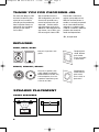
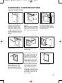
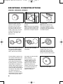
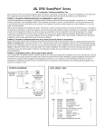
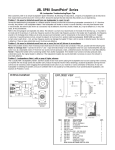
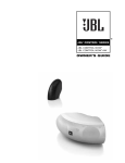
Soundpoint OM SP5-6-6C-8-8
7/7/06
9:36 AM
Page 3
®
SOUNDPOINT SERIES
®
SP5II, SP6II, SP6CII,
SP6CSII, SP8II, SP8CII
OWNER’S GUIDE
Soundpoint OM SP5-6-6C-8-8
7/7/06
9:36 AM
Page 2
THANK YOU FOR CHOOSING JBL
For more than 60 years, JBL
has been involved in every
aspect of music and film
recording and reproduction,
from live performances to
monitoring the recordings
you play in your home,
car or office.
We’re confident that the
JBL loudspeakers you have
chosen will provide every
note of enjoyment that you
expected – and that when
you think about purchasing
additional audio equipment for
your home, car or office, you
will once again choose JBL.
Please take a moment to
register your product on our
Web site at www.jbl.com. It
enables us to keep you posted
on our latest advancements,
and helps us to better understand our customers and build
products that meet their
needs and expectations.
JBL, Incorporated
INCLUDED
SP5II, SP6II, SP8II
One pair of speakers with
grilles.
Template/paint
shield. Remove
paint shield
(inner rectangle)
at perforation.
SP6CII, SP6CSII, SP8CII
One pair of speakers with
grilles (SP6CII and SP8CII).
Model SP6CSII includes only
one loudspeaker, since it is
capable of reproducing two
channels of audio.
SPEAKER PLACEMENT
FRONT SPEAKERS
WALL
400– 600
2
Template/paint
shield. Remove
paint shield
(inner circle) at
perforation.
Soundpoint OM SP5-6-6C-8-8
7/7/06
9:36 AM
Page 3
MODELS SP5II, SP6II, SP8II AS REAR SPEAKERS
5 – 6 ft.
WALL
WALL
WALL
WALL
IN-CEILING MODELS SP6CII, SP6CSII, SP8CII
Proper placement of the
speakers is an important step
in obtaining the most realistic
soundstage possible. These
recommendations are for the
optimum placement of the loudspeakers. Use these placement
recommendations as a guide.
Slight variations will not diminish your listening pleasure.
The front speakers should be
placed the same distance from
each other as they are from the
listening position. They should
be placed at about the same
height from the floor as the
listener’s ears will be, with
the tweeters aimed toward the
listener at ear-level height.
In a home theater configuration,
the two surround speakers
should be placed slightly behind
the listening position and ideally
should face each other and be
at a level higher than the listener’s ears. If that is not possi-
ble, they may be placed in a
wall (or in the ceiling) behind
the listening position, facing forward. The surround speakers
should not call attention to
themselves. They should
provide a diffuse, ambient
sound accompanying the main
program material heard in the
front speakers. In Dolby® Digital
and DTS® systems, aim the
tweeters toward the listening
position at ear-level height.
MODEL SP6CSII
Model SP6CSII has the capability of playing two channels
through one loudspeaker,
thanks to its dual-tweeter/dualvoice-coil construction. Since
the tweeters are close together,
in general they should be aimed
away from each other for best
coverage.
For two-channel (stereo) applications, e.g., as a single speaker
in a remote room of a distributed audio system, install the
SP6CSII speaker centrally in the
ceiling for best stereo imaging,
swiveling the tweeters so that
one points toward the left and
the other toward the right of the
listening position, aimed at earlevel height.
The SP6CSII may also be used
to play the left and right surround channels in a 5.1-channel
home theater system, in which
case it should be mounted in
the ceiling slightly behind the
listening position, centered
from left to right and with the
tweeters pointing toward the
left and right of the listening
position, aimed at ear-level
height.
For 7.1-channel systems where
it is desired to use two SP6CSII
speakers, one to play both the
left surround and surround
back channels and the other to
play both the right surround and
surround back channels, mount
each SP6CSII speaker in the
ceiling, slightly behind the listening position, one closer to
the left side of the room and the
other closer to the right side.
Aim the tweeters away from
each other, toward the front
and rear of the room.
3
Soundpoint OM SP5-6-6C-8-8
7/7/06
9:36 AM
Page 4
SPEAKER CONNECTIONS
CONNECTION TIPS
The wires for both speakers
should be the same length. If
one speaker is placed closer to
the amplifier than the other,
hide the excess wire behind
the wall. Speakers and electronics terminals have corresponding (+) and (–) terminals.
Most manufacturers of speakers
†
† and electronics, including JBL,
use red to denote the (+) terminal and black for the (–) terminal. It is important to connect
both speakers identically: (+) on
the speaker to (+) on the amplifier and (–) on the speaker to (–)
on the amplifier. Wiring “out
of phase” results in thin sound,
weak bass and a poor stereo
image. With the advent of multichannel surround sound
† For model SP6CSII, the terminals
for both the left and right channels systems, connecting all of the
will be on the same loudspeaker.
speakers in your system with
WIRE LENGTH
RECOMMENDED SIZE
Up to 20 ft.
Up to 30 ft.
Greater than 30 ft.
16-gauge
12-gauge
10-gauge
the correct polarity remains
equally important in order to
preserve the proper ambience
and directionality of the
program material.
To use the push-type speaker
terminals, press the red (+) or
black (–) cap for the desired
terminal, insert the bare end of
the speaker wire into the hole
below the cap and release the
cap. Gently tug on the wire
to make sure that it is fully
inserted.
INSTALLATION
The SoundPoint® Series in-wall
speakers were designed to be
easily installed. However, if you
are unsure of your ability to properly install these loudspeakers,
please contact your dealer or a
qualified installer.
4
TOOLS NEEDED
Pencil
Phillips #2 screwdriver
Measuring tape
Utility knife
Carpenter’s level
Awl
Soundpoint OM SP5-6-6C-8-8
7/7/06
9:36 AM
Page 5
EXISTING CONSTRUCTION
SP5II, SP6II, SP8II
≥1/2"
≥1/2"
≥1/2"
Remove the grille from the
speaker frame by pulling on
the paper tab. If the tab is
missing, to avoid scratching
the grille or baffle you may
unfold a paper clip, insert the
straight end through one of the
holes in the grille, and gently
pull up.
Determine the correct speaker
location.
Note: Remove the inner template,
which is the paint shield, at the
perforation. Use the outer template when cutting the drywall.
Note: Always allow at least
one-half inch between a wall
stud and the speaker cutout or
the locking tabs will not be able
to swivel into place.
Cut the drywall.
Connect the speaker wires
to the speaker.
Place the frame assembly
in the wall.
Screw down each of the four
Phillips head screws. The
locking tabs will swivel into
place and secure the unit to
the rear surface of the drywall.
The SoundPoint speakers feature unique swivel mounts for
the tweeters that enable you
to aim the very directional
high frequencies toward the
listening position, at ear-level
height. Before installing the
speaker grille, gently press on
the outer edge of the tweeter
mount to adjust the position
of the tweeter. The tweeter
will not swivel more than 15
degrees in any direction; do
not attempt to force it to move
further. You may also rotate
the tweeter to orient the JBL
logo as desired.
Replace the metal grille.
5
Soundpoint OM SP5-6-6C-8-8
7/7/06
9:36 AM
Page 6
EXISTING CONSTRUCTION
SP6CII, SP6CSII, SP8CII
≥1/2"
≥1/2"
≥1/2"
Remove the grille from the
speaker frame by pulling on
the paper tab. If the tab is
missing, to avoid scratching
the grille or baffle you may
unfold a paper clip, insert the
straight end through one of
the holes in the grille, and
gently pull up.
Determine the correct speaker
location.
Note: Remove the inner template,
which is the paint shield, at the
perforation. Use the outer template when cutting the drywall.
Cut the drywall.
Note: Always allow at least
one-half inch between a wall
stud and the speaker cutout or
the locking tabs will not be able
to swivel into place.
Connect the speaker wires to
the speaker. Model SP6CSII
requires two sets of speaker
wires, one for each channel.
Place the frame assembly
in the wall.
Screw down each of the four
Phillips head screws. The
locking tabs will swivel into
place and secure the unit to
the rear surface of the drywall.
The SoundPoint speakers feature unique swivel mounts for
the tweeters that enable you
to aim the very directional
high frequencies toward the
listening position, at ear-level
height. Before installing the
speaker grille, gently press on
the outer edge of the tweeter
mount to adjust the position of
the tweeter. The tweeter will
not swivel more than 15
degrees in any direction; do
not attempt to force it to move
further. You may also rotate
6
the tweeter to orient the JBL
logo as desired.
The dual tweeters of the
SP6CSII speaker may be
swiveled independently.
Optimum imaging will be
obtained by aiming the
tweeters to the left and right
of the listening position, at
ear-level height, if your
application permits.
Replace the metal grille.
Soundpoint OM SP5-6-6C-8-8
7/7/06
9:36 AM
Page 7
NEW CONSTRUCTION
You will need to purchase the correct rough-in frame kit for your model:
SPEAKER MODEL
ROUGH-IN FRAME KIT
SP5II
SP6II
SP6CII
SP6CSII
SP8II
SP8CII
RIF5
RIF6
RIF6C
RIF6CS
RIF8
RIF8C
Detailed installation instructions are supplied with the rough-in kit.
PAINTING THE SPEAKER
FRAME AND GRILLE
SoundPoint Series loudspeakers can be painted to
match any décor. If you wish
to change their color, the satin
finish on the grille and frame
will function as a primer coat.
Before painting, install the
paint shield (inner section of
template in the assembly kit)
securely into the recess in the
baffle. This will protect the
speaker components and baffle from paint residue. Use a
high-quality spray paint, and
apply a thin coat of color.
Be certain the grille perforations remain free of paint.
Filling them with paint will
diminish the sound quality.
Note: Gently remove the
acoustical foam blanket from
the grille before painting.
Reattach the blanket after
the paint has dried.
TROUBLESHOOTING
IF THERE IS NO
SOUND FROM ANY
OF THE SPEAKERS:
• Check that receiver/amplifier
is on and a source is playing.
• Check all wires and connections between receiver/amplifier and speakers. Make sure
all wires are connected. Make
sure none of the speaker wires
are frayed, cut, punctured or
touching each other.
• Review proper operation of
your receiver/amplifier.
IF THERE IS NO
SOUND COMING
FROM ONE SPEAKER:
• Check the “Balance” control
on your receiver/amplifier.
• Check all wires and connections between receiver/amplifier and speakers. Make sure
all wires are connected. Make
sure none of the speaker wires
are frayed, cut, punctured or
touching each other.
IF THERE IS LOW (OR
NO) BASS OUTPUT:
owner’s manual for futher
information on correct speaker
configuration in Dolby Digital,
DTS and other surround sound
modes.
• Make sure the connections
to the left and right “Speaker
Inputs” have the correct polarity (+ and –).
IF THE SYSTEM PLAYS
AT LOW VOLUMES
BUT SHUTS OFF
AS VOLUME IS
INCREASED:
• Consider adding a powered
subwoofer to your system.
• Check all wires and connections between receiver/amplifier and speakers. Make sure
all wires are connected. Make
sure none of the speaker wires
are frayed, cut , punctured or
touching each other.
• In Dolby Digital or DTS modes,
make sure your receiver/
processor is correctly configured. When using a subwoofer,
make sure the subwoofer
output of the receiver/ processor has been enabled. If no
subwoofer is being used,
make sure the left and right
front and rear speakers have
been configured as “LARGE.”
See your receiver/processor’s
• If more than one pair of main
speakers is being used, check
the minimum-impedance
requirements of your
receiver/amplifier.
7
Soundpoint OM SP5-6-6C-8-8
7/7/06
9:36 AM
Page 2
SPECIFICATIONS
SP5II
SP6II
SP6CII
SP6CSII
SP8II
SP8CII
Frequency Response
45Hz– 20kHz (–10dB)
Recommended Maximum
Amplifier Power †
60 watts
Impedance
8 ohms nominal
Sensitivity
87dB (2.83V/1m)
Crossover Frequency
3,000Hz
Woofer
5-1/4" titanium-laminate
cone w/rubber surround
Tweeter
1"titanium-laminate
dome, w/Elliptical Oblate
Spheroidal™ waveguide
and swivel mount
Plate Size (W x H)
7-1/2" x 10" (191mm x 254mm)
Mounting Cutout Size (W x H)
6-1/8" x 8-11/16" (156mm x 221mm)
Mounting Depth
3-3/4" (95mm)
Weight per Speaker
4 lb (1.8kg)
Frequency Response
38Hz – 20kHz (–10dB)
Recommended Maximum
Amplifier Power †
80 watts
Impedance
8 ohms nominal
Sensitivity
88dB (2.83V/1m)
Crossover Frequency
2,800Hz
Woofer
6-1/2" titanium-laminate
cone w/rubber surround
Tweeter
1"titanium-laminate
dome, w/Elliptical Oblate
Spheroidal™ waveguide
and swivel mount
Plate Size (W x H)
8-1/2" x 11" (216mm x 279mm)
Mounting Cutout Size (W x H)
7-1/8" x 9-11/16" (181mm x 246mm)
Mounting Depth
3-7/8" (98mm)
Weight per Speaker
5 lb (2.3kg)
Frequency Response
40Hz– 20kHz (–10dB)
Recommended Maximum
Amplifier Power †
80 watts
Impedance
8 ohms nominal
Sensitivity
88dB (2.83V/1m)
Crossover Frequency
2,600Hz
Woofer
6-1/2" titanium-laminate
cone w/rubber surround
Tweeter
1"
titanium-laminate
dome,
w/swivel mount
Plate Size (Diameter)
9-3/16" (233mm)
Mounting Cutout Size (Dia.)
7-7/8" (200mm)
Mounting Depth
4-1/4" (108mm)
Weight per Speaker
4.5 lb (2.0kg)
Frequency Response
40Hz – 20kHz (–10dB)
Recommended Maximum
Amplifier Power †
100 watts total (50WPC)
Impedance
8 ohms nominal per input
Sensitivity
88dB (2.83V/1m), both channels driven
Crossover Frequency
2,600Hz
Woofer
6-1/2" titanium-laminate
cone w/rubber surround
Tweeters
Dual 3/4"
titanium-laminate
domes,
w/swivel mounts
Plate Size (Diameter)
9-3/16" (233mm)
Mounting Cutout Size (Dia.)
7-7/8" (200mm)
Mounting Depth
4-1/4" (108mm)
Weight per Speaker
4 lb (1.8kg)
Frequency Response
30Hz – 20kHz (–10dB)
Recommended Maximum
Amplifier Power †
100 watts
Impedance
8 ohms nominal
Sensitivity
89dB (2.83V/1m)
Crossover Frequency
2,400Hz
Woofer
8" titanium-laminate
cone w/rubber surround
Tweeter
1"titanium-laminate
dome, w/Elliptical Oblate
Spheroidal™ waveguide
and swivel mount
Plate Size (W x H)
10-1/8" x 13-1/8" (257mm x 333mm)
Mounting Cutout Size (W x H)
8-7/8" x 11-13/16" (225mm x 300mm)
Mounting Depth
4" (102mm)
Weight per Speaker
7.8 lb (3.5kg)
Frequency Response
32Hz – 20kHz (–10dB)
Recommended Maximum
Amplifier Power †
100 watts
Impedance
8 ohms nominal
Sensitivity
89dB (2.83V/1m)
Crossover Frequency
2,400Hz
Woofer
8" titanium-laminate
cone w/rubber surround
Tweeter
1"titaniumlaminate
dome,
w/swivel mount
Plate Size (Diameter)
10-7/8" (275mm)
Mounting Cutout Size (Dia.)
9-1/2" (240mm)
Mounting Depth
4-1/4" (108mm)
Weight per Speaker
5.6 lb (2.5kg)
All features and specifications are subject to
change without notice.
† The maximum recommended amplifier power
rating will ensure proper system headroom to
allow for occasional peaks. We do not recommend sustained operation at these maximum
power levels.
Dolby is a registered trademark of Dolby
Laboratories.
DTS is a registered trademark of DTS, Inc.
We, Harman Consumer Group International
2, route de Tours
72500 Château du Loir
France
declare in own responsibility that the products described in this
owner’s manual are in compliance with technical standards:
EN 61000-6-3:2001
EN 61000-6-1:2001
OWNER’S GUIDE
PRODUCT
Declaration of Conformity
LINE:
SOUNDPOINT ® SERIES
Laurent Rault
Harman Consumer Group International
Château du Loir, France 7/06
PRO SOUND
COMES HOME™
SP5II, SP6II, SP6CII, SP6CSII, SP8II, SP8CII
JBL, Incorporated
250 Crossways Park Drive, Woodbury, NY 11797
8500 Balboa Boulevard, Northridge, CA 91329
516.255.4JBL (4525) www.jbl.com
DESIGN GOAL: Combine the superior performance of traditional
NOTE: For new-construction applications, be sure
to purchase the correct rough-in frame kit.
MODELS:
JBL loudspeakers with the convenience of in-wall installation.
©2006 Harman International Industries, Incorporated. All rights reserved.
TWEETER TYPE: Titanium-laminate-dome with swivel mount
WOOFER TYPE: Titanium-laminate cone with rubber surround
CROSSOVER NETWORK: Straight-Line Signal Path™ (SSP)
2
PROFESSIONAL REFERENCE: Studio Monitor
JBL, Harman International and SoundPoint are registered trademarks of
Harman International Industries, Incorporated.
Part Nos. 406-000-05268-E, 170-0091
7/06