1
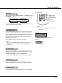
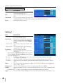
Multimedia Projector
MODEL
PDG-DXL2000
3D Ready
• DLP® Link and IR format compatible
Network Supported
Refer to the Owner's Manual below for
details about network function.
• Network Set-up and Operation
Owner’s Manual
© SANYO Electric Co., Ltd. 2010
Trademarks
• DLP is a registered trademark of Texas Instruments. BrilliantColor and DynamicBlack are trademarks of Texas
Instruments.
• HDMI, the HDMI logo and High-Definition Multimedia Interface are the trademarks or registered trademarks of
HDMI Licensing, LLC.
• Trademark PJLink is a trademark applied for trademark rights in Japan, the United States of America and other
coun-tries and areas.
• NVIDIA, the NVIDIA logo, and 3D VISION are registered trademarks and/or trademarks of NVIDIA Corporation
in the United States and other countries.
• Each name of corporations or products in this book is either a registered trademark or a trademark of its
respective corporation.
2
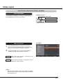
Features and Design
This Multimedia Projector is designed with the most advanced technology for portability, durability, and ease of use.
ULarge Screen in Limited Space
Short focus lens allows you to project large images
from short distance. (p.15)
U3D Display Function
This projector is capable of displaying 3D video with
the Frame Sequential Format*, and you can view the
dynamic 3D contents by wearing 3D glasses (pp.29,
48-49, 52).
* The compatible 3D image signal is only Frame
Sequential format. The Frame Packing and Side-byside formats are not supported. Active Shutter format 3D
glasses are required to view projected images in 3D. (DLP
Link and IR formats are compatible.)
UCompact Design
This projector is designed compact in size and
weight, and it can be installed overhead without
interfering with the view, or can be installed on the
floor without much space.
UMultilanguage Menu Display
The Operation menu is available in 24 languages:
English, German, French, Italian, Spanish,
Portuguese, Dutch, Swedish, Finnish, Norwegian,
Danish, Polish, Hungarian, Romanian, Russian,
Brazilian Portuguese, Turkish, Arabic, Kazakh,
Simplified Chinese, Traditional Chinese, Korean,
Japanese and Thai. (p.50)
UHelpful Maintenance Functions
Lamp and filter maintenance functions provide for
better and proper maintenance of the projector.
UDirect OFF Function
With the Direct OFF function, you can disconnect the
power cord from the wall outlet or turn off the breaker
even during projection (p.22).
UAuto Setup Function
This function enables Input search and Auto PC
adjustment by simply pressing the AUTO SET button
(pp.26, 51).
USwitchable Interface Terminal
The projector provides a switchable interface
terminal. You can use the terminal as computer input
or monitor output conveniently. (p.56)
UDigital Zoom (for Computer)
The digital zoom function allows you to focus on
crucial information during a presentation. You can
expand the images approx. 16 times the screen
size and compress them to approximately a
quarter of the screen size. (p.39)
UColorboard Function
At the time of simple projection on colored wall
or school blackboard (The board color is limited
to green.), you can get the close color image to
the color image projected on a white screen by
selecting the similar color to the wall color from the
preset colors. (pp.40, 47)
UPower Management
The Power management function reduces power
consumption and maintains lamp life. (p.57)
USecurity Features
The Security function helps you to ensure security
of the projector. With the Key lock function, you
can lock the operation on the top control or remote
control (p.59). PIN code lock function prevents
unauthorized use of the projector (pp.21, 59–60).
ULogo Function
The Logo function allows you to customize the
screen logo. The Logo page identifies the owner of
the projector. (pp.53-55)
USimple Computer System Setting
The projector has a Multi-scan system to conform
to almost all computer output signals quickly.
(p.32)
UClosed caption
Closed Caption is a function that displays the
audio portion of a TV program as text on the
screen. The closed captioning service is available
mainly in the U.S. You can turn on the feature and
switch the channels. (p.58)
ULAN Network Function
This projector is loaded with the Wired function.
You can manage the projector via network. For
details, refer to the owner’s manual “Network Setup and Operation.”
Note:
• The On-Screen Menu and figures in this manual may differ slightly from the product.
• The contents of this manual are subject to change without notice.
3
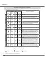
Table of Contents
Features and Design . . . . . . . . . . . . . . . . . . .3
Table of Contents . . . . . . . . . . . . . . . . . . . . . .4
To the Owner. . . . . . . . . . . . . . . . . . . . . . . . . .5
Safety Instructions . . . . . . . . . . . . . . . . . . . . .6
Air Circulation
Filter Maintenance
Moving the Projector
Installing the Projector in Proper Position
7
7
7
8
Compliance . . . . . . . . . . . . . . . . . . . . . . . . . . .9
Part Names and Functions . . . . . . . . . . . . .10
Front
Rear
Side Terminal
Top Controls and Indicators
Remote Control
Remote Control Battery Installation
Remote Control Operating Range
Remote Control Code
10
10
11
12
13
14
14
14
Installation. . . . . . . . . . . . . . . . . . . . . . . . . . .15
Positioning the Projector
Adjustable Feet
Connecting to a Computer
Connecting to Video Equipment
Connecting to Component Video Equipment
Connecting the AC Power Cord
15
15
16
17
18
19
Basic Operation . . . . . . . . . . . . . . . . . . . . . .20
Turning On the Projector
Turning Off the Projector
How to Operate the On-Screen Menu
Menu Bar
Zoom and Image Position Adjustment
Focus Adjustment
Auto Setup Function
Keystone Correction
Sound Adjustment
Remote Control Operation
20
22
23
24
25
25
26
26
27
28
Computer Input . . . . . . . . . . . . . . . . . . . . . .30
Input Source Selection (Computer 1: RGB)
Input Source Selection (Computer 2: RGB)
Computer System Selection
Auto PC adjustment
Manual PC adjustment
4
30
31
32
33
34
Image Mode Selection
Image Adjustment
Screen Size Adjustment
36
37
38
Video Input . . . . . . . . . . . . . . . . . . . . . . . . . .41
Input Source Selection (Video, S-video)
Input Source Selection (Component, Scart,
HDMI)
Image Mode Selection
Image Adjustment
Screen Size Adjustment
41
42
43
44
46
3D Display . . . . . . . . . . . . . . . . . . . . . . . . . . .48
For Viewing 3D Contents
48
Setting . . . . . . . . . . . . . . . . . . . . . . . . . . . . . .50
Setting
50
Information . . . . . . . . . . . . . . . . . . . . . . . . . .63
Input Source Information Display
63
Maintenance and Cleaning . . . . . . . . . . . . .64
WARNING TEMP. indicator
Replacing the Filter
Resetting the Filter Counter
Cleaning the Projection Window
Cleaning the Projector Cabinet
Lamp Replacement
Resetting the Lamp Counter
64
65
65
66
66
67
68
Appendix . . . . . . . . . . . . . . . . . . . . . . . . . . .69
Troubleshooting
Menu Tree
Indicators and Projector Condition
Compatible Computer Specifications
Technical Specifications
Optional Parts
PJ Link Notice
Configurations of Terminals
PIN Code Number Memo
Dimensions
69
72
74
75
77
78
78
79
80
81
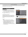
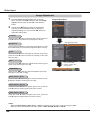
To the Owner
Before installing and operating this projector, read this
manual thoroughly.
This projector provides many convenient features and
functions. Operating the projector properly enables
you to manage those features and maintains it in good
condition for many years to come.
Improper operation may result in not only shortening the
product-life, but also malfunctions, fire hazard, or other
accidents.
If your projector seems to operate improperly, read this
manual again, check operations and cable connections
and try the solutions in the “Troubleshooting” section
in the back of this manual. If the problem still persists,
contact the dealer where you purchased the projector or
the service center.
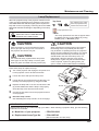
CAUTION
RISK OF ELECTRIC SHOCK
DO NOT OPEN
CAUTION:
Safety Precaution
WARNING:
L THIS APPARATUS MUST BE EARTHED.
L TO REDUCE THE RISK OF FIRE OR
ELECTRIC SHOCK, DO NOT EXPOSE THIS
APPLIANCE TO RAIN OR MOISTURE.
– This projector produces intense light from the projection
lens. Do not stare directly into the lens, otherwise eye
damage could result. Be especially careful that children
do not stare directly into the beam.
– Install the projector in a proper position. Otherwise it
may result in fire hazard.
– Allowing the proper amount of space on the top, sides,
and rear of the projector cabinet is critical for proper air
circulation and cooling of the unit. The dimension shown
here indicate the minimum space required.
If the projector is to be built into a compartment or
similarly enclosed, these minimum distances must be
maintained.
TO REDUCE THE RISK OF ELECTRIC
SHOCK, DO NOT REMOVE COVER (OR
BACK). NO USER-SERVICEABLE PARTS
INSIDE EXCEPT LAMP REPLACEMENT.
REFER SERVICING TO QUALIFIED
SERVICE PERSONNEL.
1.5' (50 cm)
THIS SYMBOL INDICATES THAT DANGEROUS
VOLTAGE CONSTITUTING A RISK OF ELECTRIC
SHOCK IS PRESENT WITHIN THIS UNIT.
THIS SYMBOL INDICATES THAT THERE ARE
IMPORTANT OPERATING AND MAINTENANCE
INSTRUCTIONS IN THE OWNER'S MANUAL
WITH THIS UNIT.
FOR EU USERS
The symbol mark and recycling systems described below
apply to EU countries and do not apply to countries in other
areas of the world.
Your product is designed and manufactured with high quality materials and components which can be recycled and/or
reused.
The symbol mark means that electrical and electronic equipment, batteries and accumulators, at their end-of-life, should
be disposed of separately from your household waste.
Note:
If a chemical symbol is printed beneath the symbol mark,
this chemical symbol means that the battery or accumulator
contains a heavy metal at a certain concentration. This will be
indicated as follows: Hg: mercury, Cd: cadmium, Pb: lead
In the European Union there are separate collection systems
for used electrical and electronic equipment, batteries and
accumulators.
Please, dispose of them correctly at your
local community waste collection/recycling
centre.
Please, help us to conserve the environment we live in!
3' (1 m)
– Do not cover the ventilation slot on the projector. Heat
build-up can reduce the service life of your projector,
and can also be dangerous.
– If the projector is unused for an extended time, unplug
the projector from the power outlet.
CAUTION
DO NOT SET THE PROJECTOR IN GREASY, WET, OR
SMOKY CONDITIONS SUCH AS IN A KITCHEN TO PREVENT
A BREAKDOWN OR A DISASTER. IF THE PROJECTOR
COMES IN CONTACT WITH OIL OR CHEMICALS, IT MAY
BECOME DETERIORATED.
CAUTION
Not for use in a computer room as defined in the
Standard for the Protection of Electronic Computer/Data
Processing Equipment, ANSI/NFPA 75.
READ AND KEEP THIS OWNER'S MANUAL FOR
LATER USE.
5
Safety Instructions
All the safety and operating instructions should be read
before the product is operated.
Do not install the projector near the ventilation duct of
air-conditioning equipment.
Read all of the instructions given here and retain them
for later use. Unplug this projector from AC power supply
before cleaning. Do not use liquid or aerosol cleaners.
Use a damp cloth for cleaning.
This projector should be operated only from the type
of power source indicated on the marking label. If you
are not sure of the type of power supplied, consult your
authorized dealer or local power company.
Follow all warnings and instructions marked on the projector.
Do not overload wall outlets and extension cords as this
can result in fire or electric shock. Do not allow anything
to rest on the power cord. Do not locate this projector
where the cord may be damaged by persons walking on
it.
For added protection to the projector during a lightning
storm, or when it is left unattended and unused for long
periods of time, unplug it from the wall outlet. This will
prevent damage due to lightning and power line surges.
Do not expose this unit to rain or use near water... for
example, in a wet basement, near a swimming pool, etc...
Do not attempt to service this projector yourself as opening or removing Covers may expose you to dangerous
voltage or other hazards. Refer all servicing to qualified
service personnel.
An appliance and cart combination
should be moved with care. Quick
stops, excessive force, and uneven
surfaces may cause the appliance
and cart combination to overturn.
Unplug this projector from wall outlet and refer servicing
to qualified service personnel under the following conditions:
a. When the power cord or plug is damaged or frayed.
b. If liquid has been spilled into the projector.
c. If the projector has been exposed to rain or water.
d. If the projector does not operate normally by following the operating instructions. Adjust only those controls that are covered by the operating instructions
as improper adjustment of other controls may result
in damage and will often require extensive work by a
qualified technician to restore the projector to normal
operation.
e. If the projector has been dropped or the cabinet has
been damaged.
f. When the projector exhibits a distinct change in performance-this indicates a need for service.
Slots and openings in the back and bottom of the cabinet
are provided for ventilation, to ensure reliable operation of
the equipment and to protect it from overheating.
When replacement parts are required, be sure the service technician has used replacement parts specified by
the manufacturer that have the same characteristics as
the original part. Unauthorized substitutions may result in
fire, electric shock, or injury to persons.
Do not use attachments not recommended by the manufacturer as they may cause hazards.
Do not place this projector on an unstable cart, stand, or
table. The projector may fall, causing serious injury to a
child or adult, and serious damage to the projector. Use
only with a cart or stand recommended by the manufacturer, or sold with the projector. Wall or shelf mounting
should follow the manufacturer’s instructions, and should
use a mounting kit approved by the manufacturers.
The openings should never be covered with cloth or other
materials, and the bottom opening should not be blocked
by placing the projector on a bed, sofa, rug, or other similar surface. This projector should never be placed near or
over a radiator or heat register.
Upon completion of any service or repairs to this projector, ask the service technician to perform routine safety
checks to determine that the projector is in safe operating condition.
This projector should not be placed in a built-in installation such as a book case unless proper ventilation is provided.
NOTE FOR CUSTOMERS IN THE US
Hg LAMP(S) INSIDE THIS PRODUCT CONTAIN
MERCURY AND MUST BE RECYCLED OR DISPOSED OF ACCORDING TO LOCAL, STATE OR
FEDERAL LAWS.
Never push objects of any kind into this projector through
cabinet slots as they may touch dangerous voltage points
or short out parts that could result in a fire or electric
shock. Never spill liquid of any kind on the projector.
6
Safety Instructions
Air Circulation
Openings in the cabinet are provided for ventilation.
To ensure reliable operation of the product and to
protect it from overheating, these openings must not
be blocked or covered.
CAUTION
Hot air is exhausted from the exhaust vent. When
using or installing the projector, the following
precautions should be taken.
– Do not put any flammable object or spray can near
the projector, hot air is exhausted from the air vents.
– Keep the exhaust vent at least 3’ (1 m) away from
any objects.
– Do not touch a peripheral part of the exhaust vent,
especially screws and metallic parts. These areas
will become hot while the projector is being used.
– Do not put anything on the cabinet. Objects put on
the cabinet will not only get damaged but also may
cause fire hazard by heat.
Cooling fans are provided to cool down the projector.
The fans’ running speed is changed according to the
temperature inside the projector.
Air Flow
Filter Maintenance
The projector uses a lamp which generates significant
heat. The cooling fans and air vents are provided to
dissipate the heat by drawing air into the housing and
the filter is located in the intake vents to prevent dust
from getting inside of the projector.
In order to care for the projector appropriately, regular
cleaning is required. Remove any dirt or dust that has
accumulated on the projector.
If the projector reaches a time set in the timer setting,
a Filter warning icon (Fig. 1) appears on the screen,
indicating that the filter replacement is necessary.
Blocking the air vents and leaving the projector
uncleaned for a long time may not only damage the
projector and may require costly repairs but may also
cause accidents or fire.
For maintenance of the filter, refer to “Filter counter”
on page 62 and “Maintenance and Care” on page 65.
Damages to the projector caused by using an
uncleaned filter or improper maintenance will void the
warranty on the projector.
Fig.1 Filter warning icon
Moving the Projector
Exhaust Vent
(Hot air exhaust)
When moving the projector, retract adjustable feet to
prevent damage to the cabinet. When the projector is
not in use for an extended period, put it into a suitable
case.
Handle the projector carefully; do not drop, bump,
subject it to strong forces, or put other things on the
cabinet.
CAUTION IN CARRYING OR
TRANSPORTING THE PROJECTOR
– Do not drop or bump the projector, otherwise
damages or malfunctions may result.
– When carrying the projector, use a suitable case.
– Do not transport the projector by courier or any
other transport service in an unsuitable transport
case. This may cause damage to the projector.
For information about transporting the projector by
courier or any other transport service, consult your
dealer.
– Do not put the projector in a case before it is
cooled enough.
7
Safety Instructions
Installing the Projector in Proper Position
Install the projector properly. Improper installation may reduce the lamp life and cause fire hazard.
Do not roll the projector more than 10 degrees from
side to side.
10˚
10˚
Do not roll the projector more than 5 degrees from
side to side when front or rear is downward.
5˚
5˚
5˚
5˚
Do not put the projector on either side to project an
image.
Note:
• Fix the projector when installing it so that the
projector would not fall down.
CAUTION
Choose the running speed of cooling fans in the fan control setting according to the altitude in which the
projector is being used (p.61). Failure to do so may affect the projector life.
CAUTION ON CEILING MOUNTING
For ceiling mounting, you need the ceiling mount kit designed for this projector. When not mounted properly,
the projector may fall, causing hazards or injury. For details, consult your dealer. The warranty on this projector
does not cover any damage caused by use of any non-recommended ceiling mount kit or installation of the
ceiling mount kit in an improper location.
Cautious use of equipment with laser technology
Do not radiate strong light such as laser light on the projection lens directly, as this may degrade the
functionality of the projector, and will void any applicable warranties.
8
Compliance
Federal Communications Commission Notice
Note: This equipment has been tested and found to comply with the limits for a Class B digital device, pursuant
to Part 15 of the FCC Rules. These limits are designed to provide reasonable protection against harmful
interference in a residential installation. This equipment generates, uses, and can radiate radio frequency
energy, and if not installed and used in accordance with the instructions, may cause harmful interference
to radio communications. However, there is no guarantee that interference will not occur in a particular
installation. If this equipment does cause harmful interference to radio or television reception, which can be
determined by turning the equipment off and on, the user is encouraged to try to correct the interference by
one or more of the following measures:
–Reorient or relocate the receiving antenna.
–Increase the separation between the equipment and receiver.
–Connect the equipment into an outlet on a circuit different from that to which the receiver is connected.
–Consult the dealer or an experienced radio/TV technician for help.
Use of shielded cable is required to comply with class B limits in Subpart B of Part 15 of FCC Rules.
Do not make any changes or modifications to the equipment unless otherwise specified in the instructions. If
such changes or modifications should be made, you could be required to stop operation of the equipment.
Model Number
: PDG-DXL2000
Trade Name
: Sanyo
Responsible party
: SANYO NORTH AMERICA CORPORATION
Address
: 21605 Plummer Street, Chatsworth, California 91311
Telephone No.
: (818)998-7322
AC Power Cord Requirement
The AC Power Cord supplied with this projector meets the requirement for use in the country you purchased it.
AC Power Cord for the United States and Canada:
AC Power Cord used in the United States and Canada is listed by the Underwriters
Laboratories (UL) and certified by the Canadian Standard Association (CSA).
AC Power Cord has a grounding-type AC line plug. This is a safety feature to be sure that the
plug will fit into the power outlet. Do not try to defeat this safety feature. Should you be unable
to insert the plug into the outlet, contact your electrician.
GROUND
AC Power Cord for the United Kingdom:
This cord is already fitted with a moulded plug incorporating a fuse, the value of which is indicated on the pin
face of the plug. Should the fuse need to be replaced, an ASTA approved BS 1362 fuse must be used of the
same rating, marked thus . If the fuse cover is detachable, never use the plug with the cover omitted. If a
replacement fuse cover is required, ensure it is of the same colour as that visible on the pin face of the plug
(i.e. red or orange). Fuse covers are available from the Parts Department indicated in your User Instructions.
If the plug supplied is not suitable for your socket outlet, it should be cut off and destroyed.
The end of the flexible cord should be suitably prepared and the correct plug fitted.
WARNING : A PLUG WITH BARED FLEXIBLE CORD IS HAZARDOUS IF ENGAGED IN A LIVE SOCKET
OUTLET.
The Wires in this mains lead are coloured in accordance with the following code:
Green-and-yellow . . Earth
Blue . . . . . . . . . . . Neutral
Brown . . . . . . . . . Live
As the colours of the wires in the mains lead of this apparatus may not correspond with the coloured markings
identifying the terminals in your plug proceed as follows:
The wire which is coloured green-and-yellow must be connected to the terminal in the plug which is marked by
the letter E or by the safety earth symbol or coloured green or green-and-yellow.
The wire which is coloured blue must be connected to the terminal which is marked with the letter N or
coloured black.
The wire which is coloured brown must be connected to the terminal which is marked with the letter L or
coloured red.
WARNING: THIS APPARATUS MUST BE EARTHED.
ASA
THE SOCKET-OUTLET SHOULD BE INSTALLED NEAR THE EQUIPMENT AND EASILY ACCESSIBLE.
9
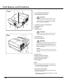
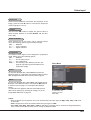
Part Names and Functions
Front
D
J
8
DTop Controls and Indicators
JInfrared Remote Receiver
CAUTION
The infrared remote receiver sticks out of the
cabinet surface. If the infrared remote receiver
is put on the wall or floor directly, the infrared
remote receiver may damage.
L
E
L
G
E
8Lamp Cover (Lamp and Air Filter)
EAdjustable feet
GSpeaker
LExhaust vent
CAUTION
Rear
H
< B
Hot air is exhausted from the exhaust vent. Do
not put heat-sensitive objects near this side.
HAir Intake vent
<Projection Window
WARNING
The projection window becomes very hot during
use. Do not put your hand or objects on the
projection window. High temperature from light
beam may damage light-blocking objects and
result in fire hazard.
Note:
;
Do not touch the projection window, otherwise,
the window may be soiled and the image can be
smudgy.
BFocus Lever
LAN Connection Terminal
Terminals and Connectors
Power Cord Connector
Security Bar
Note:
LAN Connection Terminal is for the Network
function. Refer to the owner’s manual of “Network Set-up and Operation”.
; Kensington Security Slot
This slot is for a Kensington lock used to deter
theft of the projector.
* Kensington is a registered trademark of ACCO
Brands Corporation.
10
Part Names and Functions
Side Terminal
D J
8
B
E
G
L
H
<
D S-VIDEO IN
Connect the S-VIDEO output signal from video
equipment to this jack (p.17).
< 3D SYNC OUT
Connect a 3D sync. signal cable for an IR wireless
emitter to this jack (p.48)
J VIDEO IN
Connect the composite video output signal to this
jack (p.17).
B LAN Connection Terminal
Connect the LAN cable (refer to the owner’s
manual of "Network Set-up and Operation").
8 AUDIO IN
Connect the audio output signal from video
equipment connected to D or J to this jack. For
a monaural audio signal (a single audio jack),
connect it to the L (MONO) jack (p.17).
COMPUTER IN 1/COMPONENT IN
Connect output signal from a computer, RGB scart
21-pin video output or component video output to
this terminal (pp.16, 18).
E COMPUTER 1/COMPONENT AUDIO IN
Connect the audio output (stereo) from a computer
or video equipment connected to or to this
jack (pp.16, 18).
G COMPUTER 2 AUDIO IN
Connect the audio output (stereo) from a computer
connected to to this jack (pp.16, 18).
L AUDIO OUT (VARIABLE)
Connect an external audio amplifier to this jack
(pp.16-18).
This terminal outputs sound from AUDIO IN
terminal (8, E or G) or HDMI terminal (digital
audio).
COMPUTER IN 2/MONITOR OUT
This terminal is switchable and can be used
for input from a computer or output to the other
monitor.
Set the terminal up as either Computer input or
Monitor output properly. [Used for Monitor out,
this terminal outputs only incoming signal from
COMPUTER IN 1/COMPONENT IN terminal (pp.
16, 56)].
HDMI
Connect the HDMI signal from computer or video
equipment to this terminal (pp.16, 18).
H CONTROL PORT
When controlling the projector with RS-232C,
connect the control equipment to this connector
with the serial control cable.
11
Part Names and Functions
Top Controls and Indicators
D
J
8
E
L
H
<
B
G
D POWER indicator
– Turn red when the projector is in the stand-by
mode.
– Turn green while the projector is under operation
(pp.20, 74).
– Blink green in the Power management mode
(pp.57, 74)
L ON/STAND-BY button
J WARNING TEMP. indicator
Emit a red light when the projector detects abnormal condition. This also blinks red when the internal temperature of the projector exceeds the operating range (pp. 64, 74).
< KEYSTONE button
8 LAMP REPLACE indicator
Turn yellow when the life of the projection lamp
draws to an end (pp. 67, 74).
Point 54 buttons
E 3D indicator
Turn blue when the projector is in 3D mode (pp.
48-49, 74).
Turn the projector on or off (pp.20-22).
H AUTO SETUP button
Execute the setting of Auto setup (includes Input
search function and Auto PC adj. function). (pp.26,
51)
Correct the keystone distortion (pp.26, 40, 47).
B MENU button
Open or close the On-Screen Menu (p.23).
– Select an item or adjust the value in the OnScreen Menu (p.23).
– Pan the image in Digital zoom + mode (p.39).
– Adjust the volume level (with Point buttons)
(p.27).
– Adjust the screen size (with Point 54 buttons)
(p.25).
G SELECT button
– Execute the selected item (p.23).
– Zoom in and out the image in the Digital zoom
mode (p.39).
12
Infrared Remote Receiver
The protruding shape allows wide-angle remote
control signal reception.
Part Names and Functions
Remote Control
① ON/STAND-BY button
Turn the projector on or off. (pp.2022)
② AUTO SET button
Execute the setting of Auto setup
(includes Input search function and
Auto PC adj. function). (pp.26, 51)
③ COMPUTER 1/2 buttons
Select the COMPUTER 1 or
COMPUTER 2 input source.
(pp.30-31, 42)
⑤ S-VIDEO button
Select the S-VIDEO input source. (p.41)
⑥ Point 54 buttons
– Select an item or adjust the value in the On-Screen Menu.
(p.23)
– Pan the image in the Digital zoom + mode. (p.39)
⑦ SCREEN button
Select a screen mode. (pp.29, 38-40, 46-47)
⑧ MENU button
Open or close the On-Screen Menu. (p.23)
④ VIDEO button
Select the VIDEO input source.
(p.41)
⑨ FREEZE button
Freeze the picture on the screen. (p.28)
⑩ NO SHOW button
Temporarily turn off the image on the screen. (p.29)
⑪ D.ZOOM 54 buttons
Zoom in and out the images. (pp.28, 39)
⑫ VOLUME +/- buttons
Adjust the volume level. (p.27)
①
⑬ MUTE button
Mute the sound. (p.27)
⑭ IMAGE button
Select the image mode. (pp.29, 36)
②
⑮ 3D button
Operate the 3D function. (pp.29, 48-49)
③
④
⑳
⑤
⑥
⑦
⑧
⑨
⑩
⑪
⑫
⑲
⑱
⑰
⑯
⑮
⑭
⑬
⑯ LAMP button
Select a lamp mode. (pp.28, 58)
⑰ P-TIMER button
Operate the P-timer function. (p.29)
⑱ INFO. button
Operate the information function. (pp.28, 63)
⑲ KEYSTONE button
Correct the keystone distortion. (pp.26, 40, 47)
⑳ SELECT button
– Execute the selected item. (p.23)
– Zoom in and out the image in Digital zoom mode. (p.39)
COMPONENT button
Select the COMPONENT input source. (p.42)
HDMI button
Select the HDMI input source. (p.42)
Note:
To ensure safe operation, please observe the following precautions:
• Do not bend, drop, or expose the remote control to moisture or heat.
• For cleaning, use a soft dry cloth. Do not apply benzene, thinner, spray, or any chemical material.
13
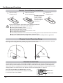
Part Names and Functions
Remote Control Battery Installation
1
Open the battery
compartment lid.
2
Install new batteries
into the compartment.
3
Replace the
compartment lid.
Two AAA size batteries
For correct polarity
(+ and –), be sure
battery terminals are
in contact with pins in
compartment.
To ensure safe operation, please observe the following precautions :
L Use two (2) AAA or LR03 type alkaline batteries.
L Always replace batteries in sets.
L Do not use a new battery with a used battery.
L Avoid contact with water or liquid.
L Do not expose the remote control to moisture or heat.
L Do not drop the remote control.
L If the battery has leaked on the remote control, carefully wipe the case clean and install new batteries.
L Risk of an explosion if battery is replaced by an incorrect type.
L Dispose of used batteries according to the instructions or your local disposal rule or guidelines.
Remote Control Operating Range
Point the remote control toward the projector (Infrared Remote Receiver) when pressing the buttons. See the
below figures indicating Maximum operating range for the remote control.
11.5’
(3.5 m)
16.4’
(5 m)
16.4’
(5 m)
Remote Control Code
The two different remote control codes (Code 1-Code 2) are assigned to this projector. Switching the remote
control codes prevents interference from other remote controls when several projectors or video equipment
next to each other are operated at the same time. Change the remote control code for the projector first before
changing that for the remote control. See "Remote control" in the Setting Menu on page 58.
Press and hold the MENU and IMAGE buttons for more
than five seconds to switch between the Code 1 and Code
2. The initial code is set to Code 1.
14
MENU button
IMAGE button
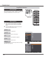
Installation
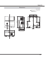
Positioning the Projector
For projector positioning, see the figures below. The projector should be set perpendicularly to the plane of the
screen.
Note:
• This projector is not equipped with an optical
zoom. To adjust the screen size, change the
throw distance.
• The brightness in the room has a great
influence on picture quality. It is recommended
to limit ambient lighting in order to obtain the
best image.
• All measurements are approximate and may
vary from the actual sizes. Make sure to check
the position of images by projecting images
on the screen before installing the projector
and screen, since each projector shows slight
variations.
• Make sure to project images on a flat screen.
• Even slight warpage or irregularities of the
screen may have an effect on the quality of the
projected images.
A
B
E
D
C
Screen
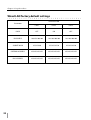
Screen Size
(W x H) mm
4:3 aspect ratio
55”
70”
90”
1118 x 838
1422 x 1067
1829x 1372
A
13.43" (34.1 cm)
16.57" (42.1 cm)
20.75" (52.7 cm)
B
9.88" (25.1 cm)
13.03" (33.1 cm)
17.20" (43.7 cm)
C
-1.77" (-4.5 cm)
1.38" (3.5 cm)
5.55" (14.1 cm)
D
9.92" (25.2 cm)
11.54" (29.3 cm)
13.62" (34.6 cm)
E
2.91" (7.4 cm)
4.53" (11.5 cm)
6.61" (16.8 cm)
Adjustable Feet
Projection angle can be adjusted within -1.0 to +1.0 degree
with the adjustable feet.
Rotate the adjustable feet and tilt the projector to the proper
height; to raise the projector, rotate the both feet clockwise.
To lower the projector or to retract the adjustable feet, rotate
the both feet counterclockwise.
To correct keystone distortion, press the KEYSTONE
button on the remote control or on the top control or select
Keystone from the menu (See pages 26, 40, 47).
Adjustable Feet
15
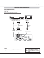
Installation
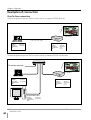
Connecting to a Computer
Cables used for connection
• VGA cables (Mini D-sub 15 pin) *
• Audio cables
• HDMI-DVI cable
(*One cable is supplied; other cables are not supplied with the projector.)
External Audio Equipment
Monitor
Output
VGA
cable
Audio
Output
Audio
cable
(stereo)
Monitor Output
or
Monitor Input
VGA
cable
VGA
cable
DVI
Output
HDMI-DVI
cable
COMPUTER 1/ COMPUTER IN 2/
COMPUTER IN 1 /
COMPONENT MONITOR OUT
COMPONENT IN
AUDIO IN
HDMI
Audio
Input
Audio cable
(stereo)
AUDIO OUT
(stereo)
This terminal is switchable. Set up the terminal
as COMPUTER IN 2 or
MONITOR OUT (P. 56).
Note:
• Input sound to the COMPUTER 1/COMPONENT AUDIO IN
terminal when using the COMPUTER IN 1/COMPONENT IN
terminal as input.
• When the cable is of the longer variety, it is advisable to
use the COMPUTER IN 1/COMPONENT IN and not the
COMPUTER IN 2 /MONITOR OUT.
• Analog RGB and component signals can be output from the
COMPUTER IN 2/MONITOR OUT terminal when using the
COMPUTER IN 2/MONITOR OUT terminal as output.
• When the AUDIO OUT is plugged-in, the projector's built-in
speaker is not available.
16
Unplug the power cords of both the
projector and external equipment
from the AC outlet before connecting
cables.
Installation
Connecting to Video Equipment
Cables used for connection
• Video and Audio cable (RCA x 3)
• S-video cable
• Audio cable
(Cables are not supplied with the projector. )
External Audio Equipment
Video and Audio Output
S-video Output (Video) (L) (R)
S-video cable
S-VIDEO IN
Video and audio
cable
VIDEO IN and AUDIO IN
Note:
• When the AUDIO OUT is plugged-in, the projector's built-in
speaker is not available.
Audio Input
Audio cable
(stereo)
AUDIO OUT (stereo)
Unplug the power cords of both the
projector and external equipment
from the AC outlet before connecting
cables.
17
Installation
Connecting to Component Video Equipment
Monitor Output Signal Table
Cables used for connection
• Audio cables
• Scart-VGA cable
• Component cable
• Component-VGA cable
• HDMI cable
(Cables are not supplied with this projector.)
Input Terminal
COMPUTER 1/
COMPONENT
D-sub15
COMPUTER 2
HDMI
S-VIDEO
VIDEO
D-sub15
HDMI
DIN-4
RCA
Monitor Out
RGB (PC analog)
Y, Pb/Cb, Pr/Cr
RGB (SCART)
RGB
HDMI
S-video
Video
YES
YES
NO
NO
NO
NO
NO
Cable
=
= A cable with one end D-sub 15 and the other end (Black box)
compatible with each equipment is necessary.
Component Video
Output
(Y, Pb/Cb, Pr/Cr)
External Audio Equipment
RGB Scart
21-pin Output
HDMI Output
Audio Output
Audio Input
Refer to
the Monitor
Output Signal Table.
Component
cable
Scart-VGA
cable
Audio cable
(stereo)
HDMI
cable
Audio cable
(stereo)
ComponentVGA cable
COMPUTER IN 1/
COMPONENT IN
COMPUTER 1/
COMPONENT
AUDIO IN
COMPUTER IN 2/
MONITOR OUT
Note:
• When the AUDIO OUT is plugged-in, the projector's built-in
speaker is not available.
• See page 78 for ordering optional cables.
18
HDMI
AUDIO OUT
(stereo)
Unplug the power cords of both the
projector and external equipment
from the AC outlet before connecting
cables.
Installation
Connecting the AC Power Cord
This projector uses nominal input voltages of 100–240 V AC
and it automatically selects the correct input voltage. It is
designed to work with single-phase power systems having a
grounded neutral conductor. To reduce the risk of electrical
shock, do not plug into any other type of power system.
If you are not sure of the type of power being supplied,
consult your authorized dealer or service center.
Connect the projector with all peripheral equipment before
turning it on.
CAUTION
Connect the AC power cord
(supplied) to the projector.
The AC outlet must be near this equipment and must be
easily accessible.
Note:
Unplug the AC power cord when the projector is not
in use. When this projector is connected to an outlet
with the AC power cord, it is in Stand-by mode and
consumes a little electric power.
NOTE ON THE POWER CORD
AC power cord must meet requirement of the country where you use the projector.
Confirm the AC plug type with the chart below and proper AC power cord must be used.
If supplied AC power cord does not match your AC outlet, contact your sales dealer.
Projector side
AC outlet side
For the U.S.A. and Canada
For Continental Europe
For the U.K.
Ground
Ground
To power cord
connector on your
projector.
To the AC outlet.
(120 V AC)
To the AC outlet.
(200 - 240 V AC)
To the AC outlet.
(200 - 240 V AC)
19
Basic Operation
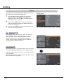
Turning On the Projector
1
Complete peripheral connections (with a computer,
VCR, etc.) before turning on the projector.
2
Connect the projector’s AC power cord into an AC
outlet. The POWER indicator lights red.
3
Press the ON/STAND-BY button on the remote
control or on the top control. The POWER indicator
lights green and the cooling fans start to operate. The
preparation display appears on the screen and the
countdown starts.
4
5
After the countdown, the input source that was
selected the last time and the lamp control status icon
(See page 58) appear on the screen.
If there is no signal input when start on the projector,
or the current signal is missed while operating the
projector, the Video / PC selection window will be
displayed on the screen, please move the pointer to
input source desired by pressing the Point 54 buttons
and press the SELECT button. And then follow the
input signal guidance window to correct the signal and
connection.
15
The preparation display will disappear after 30
seconds.
Selected Input Source and Lamp Control
Lamp control status
(See page 58 for Lamp control status.)
Note:
The Filter warning and Lamp replacement
icons may appear on the screen depending
on the usage state of the projector.
Video / PC selection window
If the projector is locked with a PIN code, PIN code
input dialog box will appear. Enter the PIN code as
instructed on the next page.
Input signal guidance window
Video / PC selection window
Note:
• When the Logo select function is set to Off, the logo will
not be shown on the screen. (p.53)
• When Countdown off or Off is selected in the Display
function, the countdown will not be shown on the screen.
(p.53)
• During the countdown period, all operations are invalid.
• When the Input search function is set to On 2, the input
signal will be searched automatically. (p.51)
• When Off is selected in the Display function, the Video
/PC selection window and the input signal guidance
window are not shown on the screen. (p.53)
20
Input signal guidance window
Basic Operation
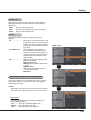
Enter a PIN code
Use the Point 54 buttons to enter a number. Press the
Point button to fix the number and move the red frame
pointer to the next box. The number changes to ;. If you
fixed an incorrect number, use the Point button to move
the pointer to the number you want to correct, and then
enter the correct number.
Repeat this step to complete entering a four-digit number.
PIN Code Input Dialog Box
After the OK icon disappears,
you can operate the projector.
After entering the four-digit number, move the pointer to
"Set". Press the SELECT button so that you can start to
operate the projector.
If you entered an incorrect PIN code, PIN code and the
number (;;;;) will turn red for a moment. Enter the correct
PIN code all over again.
What is PIN code?
PIN (Personal Identification Number) code is a security
code that allows the person who knows it to operate the
projector. Setting a PIN code prevents unauthorized use of
the projector.
A PIN code consists of a four-digit number. Refer to the PIN
code lock function in the Setting Menu on pages 59-60 for
locking operation of the projector with your PIN code.
CAUTION ON HANDLING PIN CODE
If you forget your PIN code, the projector can no
longer be started. Take a special care in setting
a new PIN code; write down the number in a
column on page 80 of this manual and keep it
on hand. Should the PIN code be missing or
forgotten, consult your dealer or service center.
Note:
• If the PIN code number is not entered within three
minutes after the PIN code dialog box appeared, the
projector will be turned off automatically.
• The “1234” is set as the initial PIN code at the factory.
21
Basic Operation
Turning Off the Projector
1
Press the ON/STAND-BY button on the remote control
or on the top control, and Power off? appears on the
screen.
2
Press the ON/STAND-BY button again to turn off the
projector. The POWER indicator starts to blink red, and
the cooling fans keep running. (You can select the level
of fans’ quietness and speed. See “Fan” on page 61.)
At this time, you can unplug the AC power cord even if
the fans are still running.
3
Power off? disappears after 4 seconds.
When the projector has cooled down enough, the
POWER indicator stops blinking and you can turn on
the projector.
TO MAINTAIN THE LIFE OF THE LAMP, ONCE
YOU TURN THE PROJECTOR ON, WAIT AT
LEAST FIVE MINUTES BEFORE TURNING IT
OFF.
DO NOT OPERATE THE PROJECTOR
CONTINUOUSLY WITHOUT REST.
CONTINUOUS USE MAY RESULT IN
SHORTENING THE LAMP LIFE. TURN OFF THE
PROJECTOR AND LET STAND FOR ABOUT AN
HOUR IN EVERY 24 HOURS.
Note:
• When the Direct on function is set to On, the projector
will be turned on automatically by connecting the AC
power cord to an AC outlet. (p. 57)
• The running speed of cooling fans is changed according
to the temperature inside the projector.
• Do not put the projector in a case before the projector is
cooled enough.
• If the WARNING TEMP. indicator blinks or lights red,
see “WARNING TEMP. indicator” on page 64.
• While the POWER indicator is blinking, the lamp is
being cooled down and the projector can not be turned
on. Wait until the POWER indicator stops blinking to turn
on the projector again.
• The fan rotation will terminate directly if the AC power
cord is unplugged immediately after the projector is
turned off.
• The projector can be turned on after the POWER
indicator turns red. The waiting time to restart will be
shortened when the normal power-off processing for fan
cooling is completed, compared with the time the AC
power cord is immediately unplugged after the poweroff.
22
Direct OFF Function
You can disconnect the power cord from the
wall outlet or turn off the breaker even during
projection without pressing the on/stand-by
button.
Note:
• When using the Direct OFF function, you can
not restart the projector immediately after
the power is disconnected. If the external
power supply is suddenly cut off, the fans
stop immediately. The lamp remains high
temperature and needs to be cooled.
Basic Operation
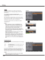
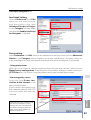
How to Operate the On-Screen Menu
The projector can be adjusted or set via the On-Screen
Menu. The menu has a hierarchical structure, with a main
menu that is divided into submenus, which are further
divided into other submenus. For each adjustment and
setting procedure, refer to respective sections in this
manual.
1
Press the MENU button on the remote control or on the
top control to display the On-Screen Menu.
2
Use the Point 54 buttons to highlight and select a
main menu item. Press the Point or the SELECT
button to access the submenu items. (The selected
item is highlighted in orange.)
3
Use the Point 54 buttons to select the desired
submenu item and press the SELECT button to set or
access the selected item.
Remote Control
POINT buttons
(arrowhead)
SELECT button
MENU button
Top Control
POINT buttons
(arrowhead)
SELECT button
MENU button
4
5
Use the Point 54 buttons to adjust the setting or
switch between each option and press the SELECT
button to activate it and return to the submenu.
On-Screen Menu
Press the Point button to return to the main menu.
Press the MENU button to exit the On-Screen Menu.
Point or SELECT
button
The currently set item is
marked.
The selected item is
highlighted in orange.
23
Basic Operation
Menu Bar
For detailed functions of each menu, see “Menu Tree” on pages 72-73.
Main Menu
Sub-Menu
①
②
③
④
⑤
⑥
⑦
⑧
⑨
⑩
① Input
Used to select an input source from Computer 1, Computer 2, HDMI, Video or
S-video. (pp.30-31, 41-42)
② PC adjust
Select Auto PC adj., Fine sync, Total dots, Horizontal, Vertical, Current mode and
Clamp to adjust the parameters to match with the PC input signal format. (pp.33-35)
③ Image select
Used to select an image mode from among Dynamic, Standard, Real, Cinema and
Image 1-4. (p.36)
④ Image adjust
For computer source, used to adjust computer image [Contrast, Brightness, Color
temp., White balance (Red/Green/Blue), Sharpness and Gamma]. (p.37)
For video or HDMI source, used to adjust picture image [Contrast, Brightness, Color,
Tint, Color temp., White balance (Red/Green/Blue), Sharpness, Gamma, Noise
reduction and Progressive]. (pp.44-45)
⑤ Screen
For computer source, used to adjust size of the image [Normal, Full, Wide (16:9), Zoom,
True, Custom, Digital zoom +/–, Keystone, Ceiling and Colorboard]. (pp.38-40)
For video or HDMI source, used to set size of image [Normal, Full, Wide (16:9), Zoom,
Custom, Keystone, Ceiling and Colorboard]. (pp.46-47)
⑥ Sound
Used to adjust the volume or mute the sound. (p.27)
⑦ Setting
Used to set the projector’s operating configurations. (pp.50-62)
⑧ Information
Display the input source information: Input, H-sync freq., V-sync freq., Screen,
Language, Lamp status, Lamp counter, Power management, Key lock, PIN code
lock, Remote control, and SERIAL NO.. (p.63)
⑨ Network
See owner’s manual of “Network Set-up and Operation”.
⑩ Guide
The key operation is displayed.
24
Basic Operation
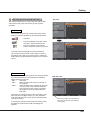
Zoom and Image Position Adjustment
Press the ZOOM +/- buttons on the top control to adjust the
screen size. Screen size can be adjusted 84% to 100% from
its maximum screen size.
Top Control
It is not available when On-Screen menu is displayed.
Zoom adjustment can be memorized. (p.52)
The image position can be adjusted in the Zoom
Adjustment.
1
ZOOM +/– buttons
Zoom +/–
Press the ZOOM+ or ZOOM- button on the top control.
Zoom +/– disappears
after 4 seconds.
2
While ZOOM+ or ZOOM- is displayed on the screen,
press the SELECT button. Arrow marks displayed on
the screen.
3
Press the Point 54 buttons on the top control or
the remote control to adjust the image position.
Screen
Image
Note:
• Zoom and Image Position Adjustment
cannot be operated when Custom is
selected in the Screen menu (pp.38, 46).
• The image position adjustment can not
be adjusted at ZOOM maximum.
• The white arrows indicate that there is no
correction.
• A red arrow indicates the direction of
correction.
• An arrow disappears at the maximum
correction.
Focus Adjustment
Adjust the lens focus with the focus lever.
Focus Lever
25
Basic Operation
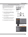
Auto Setup Function
Auto setup function is provided to automatically execute
the setting of Auto setup (includes Input search and Auto
PC adj. functions) in the Setting Menu by just pressing the
AUTO SET button on the remote control. Refer to page 51
for the setting of the Auto setup function.
Remote Control
AUTO SET button
Note:
Fine sync, Total dots, Horizontal and Vertical position of
some computers can not be fully adjusted with the Auto
PC adjustment function. When the image is not provided
properly with this operation, manual adjustments are
required. (pp.34-35)
Keystone Correction
Press the KEYSTONE button on the remote control or on
the top control. The Keystone dialog box appears. Use
the Point 54 buttons to correct keystone distortion. The
keystone adjustment can be stored (See pages 40, 47).
Reduce the upper width
with the Point 5 button.
Remote Control
Reduce the lower width
with the Point 4 button.
POINT 54 buttons
KEYSTONE button
Top Control
• The white arrows indicate that there is no correction.
• A red arrow indicates the direction of correction.
• An arrow disappears at the maximum correction.
• If you press the KEYSTONE button on the remote
control or on the top control once more while the
keystone dialog box is being displayed, the keystone
adjustment will be canceled.
• The adjustable range is limited depending on the
input signal.
26
KEYSTONE button
POINT 54 buttons
Basic Operation
Sound Adjustment
Direct Operation
Remote Control
Voume
Press the VOLUME+/– buttons on the remote control or on
the top control to adjust the volume. The volume dialog box
appears on the screen for a few seconds.
VOLUME + button
MUTE button
VOLUME - button
Mute
Press the MUTE button on the remote control to select On
to temporarily turn off the sound. To turn the sound back
on, press the MUTE button again to select Off or press the
VOLUME +/– buttons. The MUTE function is also effective
for the AUDIO OUT jack.
Top Control
VOLUME +/- buttons
Menu Operation
1
Press the MENU button to display the On-Screen Menu.
Use the Point 54 buttons to select Sound. Press the
Point or the SELECT button to access the submenu
items.
2
Use the Point 54 buttons to select the desired submenu
item and press the SELECT button to access the
selected item.
Voume
Volume Dialog Box
Approximate level
of the volume.
Press the MUTE button to set the
Mute function On or Off. The dialog
box disappears after 4 seconds.
Sound Menu
Press the Point button to turn up the volume; press the
Point button to turn down the volume.
Mute
Press the SELECT button to switch the Mute function On/
Off. When the sound is turned off, On is displayed. Press
the VOLUME +/– buttons again to turn the sound back on.
27
Basic Operation
Remote Control Operation
Using the remote control for some frequently used operations is advisable. Just pressing one of the buttons
enables you to make the desired operation quickly without calling up the On-Screen Menu.
Remote Control
COMPUTER 1, COMPUTER 2, HDMI buttons
COMPUTER 1/2
buttons
VIDEO, S-VIDEO, COMPONENT buttons
Press the COMPUTER 1/2, HDMI, VIDEO, S-VIDEO and
COMPONENT buttons on the remote control to select the
input source. See pages 30-31, 41-42 for details.
HDMI
button
S-VIDEO
button
VIDEO
button
COMPONENT
button
FREEZE buton
Press the FREEZE button on the remote control to freeze
the picture on the screen and turn off the sound. To cancel
the Freeze function, press the FREEZE button again or
press any other button.
Fig.1 will appear on the Screen menu while the Freeze
function is working.
FREEZE
button
D.ZOOM
buttons
INFO.
button
LAMP
button
Fig.1
Note:
When use the MUTE button to release the Freeze function,
the mute function can not be operated at the same time.
Note:
See the next page for the description of
other buttons.
INFO. button
Display the input source information: Input, H-sync freq.,
V-sync freq., Screen, Language, Lamp status, Lamp
counter, Power management, Key lock, PIN code lock,
Remote control and SERIAL NO.. (p.63)
D.ZOOM 54 buttons
Press the D.ZOOM 54buttons on the remote control to
enter to the D. zoom +/– mode. See page 39 for details.
LAMP button
Press the LAMP button on the remote control to select the
lamp mode for changing the brightness on the screen.
Normal ...... Normal brightness.
Eco ........... Lower brightness reduces the lamp power
consumption and extends the lamp life.
28
Basic Operation
Remote Control
3D button
Select 3D mode from 3D Off, 3D(Sync 1), 3D(Sync 2) and
3D VISION. (p.48-49)
3D Off
SCREEN button
P-TIMER button
NO SHOW button
3D(Sync 1)
3D button
3D VISION
3D(Sync 2)
IMAGE button
* The 3D indicator on the control panel emits blue at 3D (Sync 1),
3D(Sync 2) and 3D VISION. (p.48-49)
Note:
NO SHOW button
See the previous page for the description of
other buttons.
Press the NO SHOW button on the remote control to black
out the image. To restore to normal, press the NO SHOW
button again or press any other button. When the projected
image is captured and is set as User in the Logo selection
(p.53), the screen changes each time you press the NO
SHOW button as follows.
No Show
black out A the captured image A normal A • • • • •
P-Timer
No show disappears after 4 seconds.
Note:
When use the MUTE button to release the No Show
function, the mute function can not be operated at the
same time.
P-TIMER button
Press the P-TIMER button on the remote control. The Timer
display “00 : 00” appears on the screen and starts to count
time (00 : 00–59 : 59).
To stop the P-TIMER, press the P-TIMER button.
To cancel the P-TIMER, press the P-TIMER button again.
IMAGE button
Press the IMAGE button on the remote control to select a
desired image mode of the screen. See page 36 for details.
SCREEN button
Select the screen size (See pages 38-40, 46-47 for details).
29
Computer Input
Input Source Selection (Computer 1: RGB)
Direct Operation
Choose Computer 1(RGB) by pressing the COMPUTER 1
button on the remote control.
Remote Control
Before using these buttons, correct input source should be
selected through Menu operation as described below.
COMPUTER 1 button
Computer 1(RGB)
Computer 1(Scart)
Input Menu
Menu Operation
1
Press the MENU button to display the On-Screen
Menu. Use the Point 54 buttons to select Input and
then press the Point or the SELECT button.
2
Use the Point 54 buttons to select Computer 1.
3
When Computer 1 is selected, press the Point to
access the submenu items. Use the Point 54 buttons
to select the RGB input source and then press the
SELECT button.
Computer
1
Note:
When the Input Search function is set to On 1 or On 2 in
the Auto setup function, the input signal will be searched
automatically (p.51).
30
Computer Input
Input Source Selection (Computer 2: RGB)
Direct Operation
Choose Computer 2 (RGB) by press the COMPUTER 2
button on the remote control.
Remote Control
COMPUTER 2 button
Computer 2 (RGB)*
Note:
* COMPUTER 2 can not be selected when
using the COMPUTER IN 2/ MONITOR
OUT terminal as MONITOR OUT.
"Monitor out" message will appear on the
screen when COMPUTER 2 button is
pressed while using the COMPUTER IN
2/ MONITOR OUT terminal as MONITOR
OUT.
Menu Operation
1
Press the MENU button to display the On-Screen
Menu. Press the Point 54 buttons, move the highlight
to Input and then press the Point or the SELECT
button.
2
Use the Point 54 buttons to select Computer 2 and
then press the SELECT button.
3
When Computer 2 is selected, analog RGB input
source will be selected directly.
Input Menu
Note:
When the Input Search function is set to On 1 or On 2 in
the Auto setup function, the input signal will be searched
automatically (p.51).
31
Computer Input
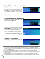
Computer System Selection
This projector automatically tunes to various types of computers with its Multi-scan system and Auto PC
adjustment. If a computer is selected as a signal source, this projector automatically detects the signal format
and tunes to project a proper image without any additional settings. (Signal formats provided in this projector are
shown on pages 75-76.)
One of the following messages may appear when:
Auto
When the projector can not recognize the
connected signal conforming to the provided
PC Systems, Auto is displayed on the System
Menu box and the Auto PC adjustment function
works to display proper images. If the image is
not projected properly, a manual adjustment is
required. (pp.34-35)
-----
There is no signal input from the computer.
Check the connection between your computer
and the projector. (See “Troubleshooting” on
page 69.)
Mode 1
The preset system is manually adjusted in the
PC adjust Menu. The adjusted data can be
stored in Mode 1-10. (pp.34-35)
XGA 1
PC System Menu
Selected system in the PC
System Menu is displayed.
PC Systems provided in this projector is chosen.
The projector chooses a proper system provided
in the projector and displays it.
* Mode 1 and XGA 1 are examples.
Selecting Computer System Manually
PC system can also be selected manually.
1
Press the MENU button to display the On-Screen
Menu. Use the Point 54 buttons to select Input and
then press the Point or the SELECT button.
2
Use the Point 54 buttons to select System and then
press the Point or the SELECT button.
3
Use the Point 54 buttons to select the desired system
and then press the SELECT button.
PC System Menu
Customized Mode (1–10)
set in the PC adjust Menu
(pp.34-35).
Systems in this dialog box
can be selected.
32
Computer Input
Auto PC adjustment
Auto PC adjustment function is provided to automatically adjust Fine sync, Total dots, Horizontal , Vertical
and Clamp position to conform to your computer.
Menu Operation
Auto PC adj.
1
Press the MENU button to display the On-Screen
Menu. Use the Point 54 buttons to select PC adjust
and then press the Point or the SELECT button.
2
Use the Point 54 buttons to select Auto PC adj. and
then press the SELECT button.
To store adjustment parameters
The adjusted parameters from the Auto PC adjustment can
be stored in the projector. Once the parameters are stored,
the setting can be done just by selecting a Mode (1–10) in
the PC System Menu (See page 32). See also “Store” on
page 35.
PC adjust Menu
Use Point 54 buttons to select Auto PC
adj. and press the SELECT button.
Please wait... appears while the Auto PC
adjustment is in process.
Note:
• Fine sync, Total dots, Horizontal and Vertical
position of some computers can not be fully adjusted
with the Auto PC adjustment function. When the image
is not provided properly with this operation, manual
adjustments are required (pp.34-35).
• The Auto PC adjustment can not be operated when
480i, 575i, 480p, 575p, 720p or 1080i is selected in the
PC System Menu (p.32) , or when the signal is coming
from the HDMI terminal.
33
Computer Input
Manual PC adjustment
Some computers employ special signal formats which may not be tuned by Multi-scan system of this projector.
Manual PC adjustment enables you to precisely adjust several parameters to match those signal formats. The
projector has five independent memory areas to store those parameters manually adjusted. It allows you to
recall the setting for a specific computer.
1
Press the MENU button to display the On-Screen
Menu. Use the Point 54 buttons to select PC adjust
and then press the Point or the SELECT button.
2
Use the Point 54 buttons to select the desired item
and then press the SELECT button to display the
adjustment dialog box. Use the Point buttons to
adjust the setting value.
Fine sync
Use the Point buttons to adjust the value, eliminating a
flicker from the image displayed (from 0 to 31).
Total dots
Use the Point buttons to adjust the number of total dots
in one horizontal period to match your PC image.
Horizontal
Use the Point buttons to adjust the horizontal picture
position.
Vertical
Use the Point buttons to adjust the vertical picture
position.
Current mode
Press the SELECT button to show H-sync freq. and V-sync
freq. of the connected computer.
Clamp
Use the Point buttons to adjust the clamp level. When
the image has dark bars, try this adjustment.
Note:
Fine sync and Total dots cannot be selected when the
input signal is 480i, 480p, 575i, 575p, 720p or 1080i.
34
PC adjust Menu
Computer Input
Reset
To reset the adjusted data, select Reset and press the
SELECT button. A confirmation box appears and then select
Yes. All adjustments will return to their previous figures.
Mode free Menu
Mode free
To clear the stored data, select Mode free and then press
the Point or the SELECT button. Move the highlight to the
Mode that you want to clear and then press the SELECT
button.
This Mode has stored
parameters.
Store
To store the adjusted data, select Store and then press the
Point or the SELECT button. Move the highlight to one
of the Modes 1 to 10 in which you want to store, and then
press the SELECT button.
Note:
• When input computer signal to the projector, PC adjust
will become available.
Values of Total dots, Horizontal,
and Vertical.
Store Menu
Press MENU button
to close this dialog
box.
Vacant
Press SELECT button to
store adjusted data.
35
Computer Input
Image Mode Selection
Direct Operation
Remote Control
Select the desired image mode among Dynamic, Standard,
Real, Cinema, Image 1, Image 2, Image 3, and Image 4 by
pressing the IMAGE button on the remote control.
IMAGE button
Dynamic
Standard
Real
Cinema
IMAGE button
Image 1
Image 2
Menu Operation
1
2
Image 3
Press the MENU button to display the On-Screen
Menu. Use the Point 54 buttons to select Image
select and then press the Point or the SELECT
button.
Image 4
Use the Point 54 buttons to select the desired item
and then press the SELECT button.
Dynamic
For viewing pictures in a bright room.
Standard
Normal picture mode preset on the projector.
Real
Picture mode with improved halftone for graphics.
Cinema
Picture mode adjusted with fine tone.
Image 1-4
For viewing with the user preset image mode in the Image
adjust Menu (See page 37).
36
Image Select Menu
Computer Input
Image Adjustment
1
Press the MENU button to display the On-Screen
Menu. Use the Point 54 buttons to select Image
adjust and then press the Point or the SELECT
button.
2
Use the Point 54 buttons select the desired item
and then press the SELECT button to display the
adjustment dialog box. Use the Point buttons to
adjust the setting value.
Image adjust Menu
Contrast
Press the Point button to decrease the contrast; press the
Point button to increase the contrast (from 0 to 63).
Selected Image mode
Brightness
Press the Point button to decrease the brightness; press
the Point button to increase the brightness (from 0 to 63).
Color temp.
Use the Point buttons to select the desired Color temp.
level (XLow, Low, Mid, or High).
White balance (Red / Green / Blue)
Press the Point button to lighten R/G/B tone; press the
Point button to deepen R/G/B tone (from 0 to 63).
Use the Point buttons to adjust the
setting value.
Sharpness
Press the Point button to decrease the sharpness of the
image; press the Point button to increase the sharpness
of the image (from 0 to 15).
Gamma
Use the Point buttons to adjust the gamma value to
obtain a better balance of contrast (Default, 1.8, 2.0, 2.2,
2.4, or 2.6).
Note:
• When White balance Red, Green or Blue is
adjusted, Color temp. will change to User.
Store Menu
Reset
To reset the adjusted data, select Reset and press the
SELECT button. A confirmation box appears and then select
Yes. All adjustments will return to their previous figures.
Store
To store the adjusted data, select Store and press the Point
or the SELECT button. Use the Point 54 buttons to
select one from Image 1 to 4 and press the SELECT button.
A confirmation box appears and then select Yes. Stored
data can be called up by selecting an Image (1-4) in the
Image Mode Selection on page 36.
A confirmation box appears and
then select Yes.
37
Computer Input
Screen Size Adjustment
This projector has the picture screen resize function, which
enables you to customize the image size.
1
Press the MENU button to display the On-Screen
Menu. Use the Point 54 buttons to select Screen and
then press the Point or the SELECT button.
2
Use the Point 54 buttons select the desired item and
then press the SELECT button .
Screen Menu
Normal
Provide the image to fit the screen size while maintaining
the aspect ratio of input signal.
Full
Provide the full screen image.
Wide (16:9)
Provide the image at the 16:9 wide screen ratio.
Zoom
Scale the image proportionally to fit the entire screen. Either
side of image may go over the screen.
True
Provide the image in its original size. When the original
image size is larger than the screen size (1024 x 768), the
projector automatically switches to the panning mode. Use
the Point 54 buttons to pan the image. When adjusted,
the arrows turn red. When reached to the correction limit,
the arrows disappear.
Custom
Provide the last stored aspect screen image.
Note:
• This projector can not display any resolution higher than 1920 x 1200. If your computer’s resolution is higher
than that, lower the resolution before connecting to the projector.
• The image data other than 1024 x 768 is modified to fit the screen size in initial mode.
• True and Digital zoom +/– can not be selected when 480i, 575i, 480p, or 575p is selected in the PC System
Menu (p.32).
• Zoom and Image Position Adjustment (p.25) will be canceled when Custom is selected in the Screen menu.
38
Computer Input
Custom adj.
Adjust the screen scale and position manually with this
function.
Press the Point button at Custom adj. and the Custom
adjustment menu is displayed on the screen, you can use
the Point 54 buttons to choose the item you want to adjust.
Scale H/V .......... Adjust the Horizontal/Vertical screen
scale.
H&V ................... When set to On, the aspect ratio is fixed.
Scale V appears dimmed and becomes
unavailable. Adjust Scale H, then the
screen scale is automatically modified
based on the aspect ratio.
Position H/V ..... Adjust the Horizontal/Vertical screen
position.
Common ........... Save the adjusted scale or position to all
the inputs. Press the SELECT button at
Common to display a confirmation box.
To save the scale or position, press the
SELECT button at "Yes". When Custom
is selected, the saved scale or position is
used.
Reset................. Reset the all adjusted values. Press
the SELECT button at Reset to display
a confirmation box. To reset, press the
SELECT button at "Yes".
Custom adj. Menu
Note:
• When no signal is detected, Normal is set
automatically and Custom adj. cannot
be selected and the Aspect dialog box
disappears.
• The adjustable range for Scale H/V and
Position H/V is limited depending on the
input signal.
D.ZOOM +/–
Remote Control
Digital zoom +
POINT54
buttons
Select Digital zoom +. The On-Screen Menu disappears
and D. zoom + appears. Press the SELECT button to
expand the image size. Use the Point 54 buttons to
pan the image. The Panning function can work only when
the image is larger than the screen size.
A projected image can be also expanded by pressing the
D.ZOOM 5 or the SELECT button on the remote control.
SELECT button
D.ZOOM 5 button
D.ZOOM 4 button
Digital zoom –
Select Digital zoom -. The On-Screen Menu disappears and
D. zoom - appears. Press the SELECT button to compress
image size.
The projected image can be also compressed by pressing
the D.ZOOM 4 or the SELECT button on the remote control.
To exit the Digital zoom +/– mode, press any button except
the D.ZOOM 54 and the SELECT buttons.
To return to the previous screen size, select a screen size
from the Screen Size Adjustment Menu or select an input
source from the Input Source Selection Menu (See pages
30-31) again, or adjust the screen size with the D.ZOOM
54 buttons.
Note:
• The panning function may not operate
properly if the stored Mode in the PC adjust
Menu is used (p.35).
• The minimum compression ratio is limited
depending on the input signal, when the
Keystone function is working or when
Custom is selected for the screen size.
• True and Digital zoom +/- can not be
selected when 480i, 575i, 480p, or 575p is
selected in the PC System Menu (p.32).
• Digital zoom +/- can not be selected when
True is selected in the Screen menu. (p.38)
39
Computer Input
Keystone
Keystone
This function is used to adjust keystone distortion of the
projected image. Use the Point 54 buttons to choose the
item you want to adjust.
Keystone
To correct keystone distortion, press the SELECT button.
Keystone appears on the screen. Use the Point 54
buttons to correct keystone distortion (p.26).
Store or Reset
To store or reset the keystone correction, press the Point
button.
Store ..... Keep the keystone correction even when the AC
power cord is unplugged.
Reset..... Release the keystone correction when the AC
power cord is unplugged.
Ceiling
When this function is set to On, the picture will be top/
bottom and left/right reversed. This function is used to
project the image from a ceiling-mounted projector.
Rear
When this function is set to On, the picture will be left/right
reversed. This function is used to project the image from
rear of the screen.
Ceiling
Colorboard
Press the Point button at Colorboard, and then use the
Point 54 buttons to switch the desired item [Red, Blue,
Yellow, Green, Blackboard(Green)] and then press the
SELECT button.
At the time of simple projection on the colored wall, you can
get the close color image to the color image projected on a
white screen by selecting the similar color to the wall color
from the preset colors.
Reset
To reset the adjusted data, select Reset and press the
SELECT button. A confirmation box appears and then select
Yes. All adjustments will return to their previous figures.
40
Rear
Video Input
Input Source Selection (Video, S-video)
Direct Operation
Choose Video or S-video by pressing the VIDEO button or
the S-VIDEO button on the remote control.
Remote Control
VIDEO button
Video
S-VIDEO button
S-video
Menu Operation
1
Press the MENU button to display the On-Screen
Menu. Use the Point 54 buttons to select Input and
then press the Point or the SELECT button.
2
Use the Point 54 buttons to select either Video or
S-video and then press the SELECT button.
Video
When video input signal is connected to the
VIDEO jack, select Video.
S-video
When video input signal is connected to the SVIDEO jack, select S-video.
Input Menu
Note:
When the Input Search function is set to On 1 or On 2 in
the Auto setup function, the input signal will be searched
automatically (p.51).
41
Video Input
Input Source Selection (Component, Scart, HDMI)
Direct Operation
Remote Control
Choose Computer 1(Component) or Computer 1(Scart)
by pressing the the COMPONENT or COMPUTER 1 button
on the remote control; choose HDMI by pressing the HDMI
button on the remote control.
COMPUTER 1 button
Computer 1 (RGB)
Before using these buttons, correct input source should be
selected through Menu operation as described below.
HDMI button
HDMI
Computer 1 (Scart)
COMPONENT button
Computer 1
(Component)
Menu Operation
1
Press the MENU button to display the On-Screen
Menu. Use the Point 54 buttons to select Input and
then press the Point or the SELECT button.
2
Use the Point 54 buttons to select Computer 1 and
then press the Point button; use the Point 54
buttons to select Component or RGB(Scart) and then
press the SELECT button.
OR
Use the Point 54 buttons to select HDMI, and then
press the SELECT button;
Component
When the input source is coming from video
equipment connected to the COMPUTER
IN 1/COMPONENT IN terminal with a
Component-VGA Cable, select Component.
RGB (Scart) When the input source is coming from video
equipment connected to the COMPUTER
IN 1/COMPONENT IN terminal with a ScartVGA Cable, select RGB (Scart).
HDMI
When the video signal is connected to the
HDMI terminal, select HDMI.
Note:
When the Input Search function is set to On 1 or On 2 in
the Auto setup function, the input signal will be searched
automatically (p.51).
42
Input Menu
Video Input
Image Mode Selection
Direct Operation
Remote Control
Select the desired image mode among Dynamic, Standard,
Real, Cinema, Image 1, Image 2, Image 3, and Image 4 by
pressing the IMAGE button on the remote control.
IMAGE button
Dynamic
Standard
Real
Cinema
IMAGE button
Image 1
Image 2
Menu Operation
1
2
Image 3
Press the MENU button to display the On-Screen
Menu. Use the Point 54 buttons to select Image
select and then press the Point or the SELECT
button.
Image 4
Use the Point 54 buttons to select the desired item
and then press the SELECT button.
Dynamic
For viewing pictures in a bright room.
Standard
Image Select Menu
Normal picture mode preset on the projector.
Real
Picture mode with improved halftone for graphics.
Cinema
Picture mode adjusted with fine tone.
Image 1-4
For viewing with the user preset image mode in the Image
adjust Menu (See pages 44, 45).
43
Video Input
Image Adjustment
1
Press the MENU button to display the On-Screen
Menu. Use the Point 54 buttons to select the Image
adjust and then press the Point or the SELECT
button.
2
Use the Point 54 buttons select the desired item
and then press the SELECT button to display the
adjustment dialog box. Use the Point buttons to
adjust the setting value.
Image adjust Menu
Contrast
Press the Point button to decrease the contrast; press the
Point button to increase the contrast (from 0 to 63).
Selected Image mode
Brightness
Press the Point button to decrease the brightness; press
the Point button to increase the brightness (from 0 to 63).
Color
Press the Point button decrease the intensity of the color;
press the Point button increase the intensity of the color
(from 0 to 63).
Tint
Press the Point buttons to adjust the tint value to get a
proper color balance (from 0 to 63).
Use the Point buttons to adjust the
setting value.
Color temp.
Use the Point buttons to select the desired Color temp.
level (Xlow, Low, Mid, or High).
White balance (Red)
Press the Point button to lighten red tone; press the Point
button to deepen red tone (from 0 to 63).
White balance (Green)
Press the Point button to lighten green tone; press the
Point button to deepen green tone (from 0 to 63).
White balance (Blue)
Press the Point button to lighten blue tone; press the
Point button to deepen blue tone (from 0 to 63).
Note:
• When the White balance Red, Green, or Blue is adjusted, the Color temp. level will change to User.
• Tint can not be selected when the video system is PAL, SECAM, PAL-M, or PAL-N.
44
Video Input
Sharpness
Press the Point button to decrease the sharpness of the
image; press the Point button to increase the sharpness
of the image (from 0 to 15).
Gamma
Use the Point buttons to adjust the gamma value to
obtain a better balance of contrast (Default, 1.8, 2.0, 2.2,
2.4, or 2.6).
Noise reduction
Noise interference on the screen can be reduced. Select
one of the following options to get smoother images.
Off ......... Disabled.
L 1 ......... Lower reduction.
L 2 ......... Higher reduction.
Progressive
An interlaced video signal can be displayed in progressive
mode. Select one of the following options.
Off ......... Disabled.
L 1 ......... For an active picture.
L 2 ......... For a still picture.
Film ....... For watching a film. With this function, the
projector reproduces pictures faithful to the
original film quality.
Store Menu
Reset
To reset the adjusted data, select Reset and press the
SELECT button. A confirmation box appears and then select
Yes. All adjustments will return to their previous figures.
Store
To store the adjusted data, select Store and press the Point
button or the SELECT button. Use the Point 54 buttons
to select one from Image 1 to 4 and press the SELECT
button.
A confirmation box appears and then select Yes. Stored
data can be called up by selecting an Image (1-4) in the
Image Mode Selection on page 43.
A confirmation box
appears and then
select Yes.
Note:
• Noise reduction and Progressive can not be selected when the input signal is 480p, 575p, 720p or 3D mode
is set to On.
• Film of Progressive cannot be selected when the input signal is 1080i.
• When 480i, 575i, 480p, 575p,720p or 1080i is selected in computer source, the items of Image adjustment
are the same as the items in video source, except for Color and Tint.
45
Video Input
Screen Size Adjustment
This projector has the picture screen resize function, which enables you to customize the image size.
1
Press the MENU button to display the On-Screen
Menu. Use the Point 54 buttons to select Screen and
then press the Point or the SELECT button.
2
Use the Point 54 buttons select the desired item and
then press the SELECT button.
Screen Menu
Normal
Provide the image to fit the screen size while maintaining
the aspect ratio of input signal.
Full
Provide the full screen image.
Wide(16:9)
Provide the image at the 16:9 wide screen ratio.
Zoom
Pan the horizontal direction of the image and cut the vertical
direction of the image to fit the screen size (16:9). Only for 4:3
video aspect ratio signals.
Custom
Provide the last stored aspect screen image.
Custom adj.
Adjust the screen scale and position manually with this
function.
Press the Point button at Custom adj. and the Custom
adjustment menu is displayed on the screen, you can use
the Point 54 buttons to choose the item you want to adjust.
Scale H/V ........Adjust the Horizontal/Vertical screen scale.
H&V .................When set to On, the aspect ratio is fixed.
Scale V appears dimmed and becomes
unavailable. Adjust Scale H, then the screen
scale is automatically modified based on the
aspect ratio.
Position H/V ...Adjust the Horizontal/Vertical screen
position.
Common .........Save the adjusted scale or position to all
the inputs. Press the SELECT button at
Common to display a confirmation box.
To save the scale or position, press the
SELECT button at "Yes", When Custom is
selected, the saved scale or position is used.
Reset...............Reset the all adjusted values. Press
the SELECT button at Reset to display
a confirmation box. To reset, press the
SELECT button at "Yes".
46
Note:
• When no signal is detected, Normal
is set automatically and the Aspect
adjustment menu disappears.
• The adjustable range for Scale H/V and
Position H/V is limited depending on the
input signal.
Video Input
Keystone
Keystone
This function is used to adjust keystone distortion of the
projected image. Use the Point 54 buttons to choose the
item you want to adjust.
Keystone
To correct keystone distortion, press the SELECT button.
Keystone appears on the screen. Use the Point 54
buttons to correct keystone distortion (p.26).
Store or Reset
To store or reset the keystone correction, press the Point
button.
Store ..... Keep the keystone correction even when the AC
power cord is unplugged.
Reset..... Release the keystone correction when the AC
power cord is unplugged.
Ceiling
When this function is set to On, the picture will be top/
bottom and left/right reversed. This function is used to
project the image from a ceiling-mounted projector.
Rear
When this function is set to On, the picture will be left/right
reversed. This function is used to project the image from
rear of the screen.
Ceiling
Colorboard
Press the Point button at Colorboard, and then use the
Point 54 buttons to switch the desired item [Red, Blue,
Yellow, Green, Blackboard(Green)] and then press the
SELECT button.
Rear
At the time of simple projection on the colored wall, you can
get the close color image to the color image projected on a
white screen by selecting the similar color to the wall color
from the preset colors.
Reset
To reset the adjusted data, select Reset and press the
SELECT button. A confirmation box appears and then select
Yes. All adjustments will return to their previous figures.
47
3D Display
For Viewing 3D Contents
To view 3D images, you need to prepare at least the 3D active shutter glasses, 3D content and 3D reproducing
equipment. For example, as for computer, when transmitting 3D signals from a computer to the projector, you
also need to install the graphic card which has the capability to sequentially output the 3D frames at 120Hz and
software in the computer. The 3D signal type which the projector can accept is frame sequential only. Other 3D
signal types such as frame packing and side-by-side are not supported.
As for 3D glasses, DLP Link format and IR emitter format are compatible with this projector. Compatibility with
any other 3D glasses than the 2 types 3D glasses is not guaranteed.
Remote Control
In a situation of using NVIDIA® 3D glasses, NVIDIA IR emitter, and
a computer which NVIDIA graphics card is installed, when you want
to view NVIDIA-compatible 3D contents, please set to NVIDIA 3D
VISION mode.
* COMPUTER IN 2/MONITOR OUT terminal is not supported NVIDIA® 3D VISION™.
Please input the image signals to COMPUTER IN 1/COMPONENT IN or HDMI terminal.
3D button
3D Mode
Using 3D Glasses with DLP Link compatible
3D Off
When using DLP Link compatible glasses, follow these
steps:
1. Turn on the projector and the 3D glasses.
2. Wear the 3D glasses and press the 3D button on the
remote control to activate 3D Display function.
When 3D mode is in On, 3D indicator turns blue.
3. If you see a discrete or overlapping image, 3D Sync
Invert function enables you to get the correct image.
Press the 3D button to switch 3D Sync signal from among
"3D Off", "3D (Sync 1)", "3D (Sync 2)" or "3D VISION".
3D (Sync 1)
LCD Glasses with DLP
Link compatible
3D (Sync 2)
3D VISION
Infrared Emitter
3D SYNC Input
3D setting can also be selected from the menu (p.52).
Stereoscopic Wireless
LCD Glasses
Sync Signal Cable
(Supplied with the IR Emitter)
Using 3D Glasses with IR wireless emitter
When using IR emitter system, follow these steps:
1. Turn off the projector.
2. Connect the sync cable for the IR emitter to 3D SYNC
OUT terminal of the projector.
3. Turn on the projector, the IR emitter and the stereoscopic
wireless LCD glasses.
4. Wear the 3D glasses and press the 3D button on the
remote control to activate 3D Display function.
5. If you see a discrete or overlapping image, press the 3D
button to switch 3D Sync signal from among "3D Off", "3D
(Sync 1)", "3D (Sync 2)" or "3D VISION".
You can also invert the sync signal by using the switch on
the IR emitter.
48
3D SYNC OUT
Unplug the power cords of both the
projector and external equipment from
the AC outlet before connecting cables.
3D Display
CAUTION FOR PROPERLY VIEWING 3D PICTURES
- The optimum 3D viewing distance from the screen
is about 3 m or more and your eyes should be level
with the screen.
- Viewing 3D images for an extended period of time or
viewing them from an oblique angle can cause eye
strain.
- Take breaks when viewing 3D images for an
extended period of time. As this may cause eye
fatigue.
- Some image sources can cause pseudoscopic
image problem. Check the 3D settings to get the 3D
effect.
- If the right-eye image and left-eye image are
switched, you may not get the 3D effect, resulting in
eye strain or nausea.
- There are differences in 3D visual perception
between individuals.
- If you get double vision or don’t get the 3D effect,
discontinue using the projector.
- If you experience fatigue or nausea, stop using the
projector.
- After viewing the rotating, swinging, or jumping 3D
images, you may experience 3D motion sickness.
- If you experience such symptom, immediately stop
viewing the 3D images and take a break until the
symptom has subsided.
- If you view 3D images in bright ambient light
environment, you may not able to see them clearly.
Or if you use the 3D glasses in a room which
fluorescent lighting (50Hz), flickering may occur. If
these happen, change the room lighting condition by
making the room dark or turning off the light.
RESTRICTIONS ON VIEWING 3D IMAGES
- Children who are six year of age or younger should
not view 3D images.
- Parents should accompany and monitor their
children as children cannot properly express
discomfort with 3D image viewing.
- Photosensitive patients, patients with heart disease,
pregnant women, elderly people, and people with
serious illness and/or with a history of epilepsy
should not view 3D images
- We advise that you should refrain from viewing 3D
images if you are in bad physical condition
- We do not recommend viewing 3D images if you
need sleep or have been drinking alcohol.
TROUBLESHOOTING FOR 3D DISPLAY
Symptoms
Possible problems
3D contents appear as 2D.
The glasses or the projector are set
to 2D mode.
3D mode is out of phase. (The data
for right/left eyes is inverted.)
3D image is inverted. (3D image
is not correct.)
Image of glasses has flicker.
Glasses does not turn on.
Solution
Change the setting of the glasses or the
projector.
Reverse the 3D sync phase of the projector
by using 3D button on the remote control or
through the Setting menu of the projector.
Outside of the recommended viewing Move your position closer to the emitter.
zone of the glasses.
- The battery of the glasses is
- Recharge the battery.
exhausted.
- Change the setting of the projector.
- The projector is not set to 3D mode.
49
Setting
Setting
This projector has a Setting Menu that allows you to set up
the other various functions described below.
1
Press the MENU button to display the On-Screen
Menu. Press the Point 54 buttons to select the
Setting and press the Point or the SELECT button
to access the submenu items.
2
Use the Point 54 buttons to select the desired item
and then press the Point or the SELECT buttons to
access the selected item.
3
Use the Point 54 buttons select the desired item and
then press the SELECT button.
Setting Menu
Language
The language used in the On-Screen Menu is available in
English, German, French, Italian, Spanish, Portuguese,
Dutch, Swedish, Finnish, Norwegian, Danish, Polish,
Hungarian, Romanian, Russian, Brazilian Portuguese,
Turkish, Arabic, Kazakh, Simplified Chinese, Traditional
Chinese, Korean, Japanese and Thai.
Menu position
This function is used to change the position of the On-Screen
Menu. Select Menu position and press the SELECT button.
The Menu position changes each time you press the SELECT
button as follows.
the center A the bottom left A the bottom right A the top left
A the top left A the top right A .....
50
Language Menu
Setting
Auto setup
This function enables Input search and Auto PC adjustment by
pressing the AUTO SET button on the remote control. Settings
for those functions can be altered as follows:
Auto setup
Input search
This function detects the input signal automatically. When
a signal is found, the search will stop. Use the Point 54
buttons to select one of the following options.
Off ......... Input search dose not work.
On 1....... Input search works under the following situation.
– When pressing the AUTO SET button on the
remote control.
On 2....... Input search works under the following situation.
– When turning on the projector by pressing the
ON/STAND-BY button.
– When pressing the AUTO SET button on the
remote control.
– When the current input signal is cut off.*
* If the No show or Freeze function is active, cancel
it to activate the Input search. It is also unavailable
when On-Screen Menu is displayed.
Auto PC adj.
On. . . . . . . Enables Auto PC adjustment when pressing
the AUTO SET button on the remote control.
Off . . . . . . Disables Auto PC adjustment.
Note:
• While Input search function is set to On 1 or On 2, the status of Input and Lamp are displayed every time the
signal is switched.
• Only the last selected input source can be detected.
• If the COMPUTER 1/2 button, VIDEO, S-VIDEO, COMPONENT or HDMI button on the remote control,
or ON/STAND-BY or MENU button on the top control is pressed during Input search is in progress, Input
search will stop and go back to the previous input signal.
• Auto PC adj. and Input search functions can not be set Off at the same time.
• Fine sync, Total dots, Horizontal and Vertical positions of some computers can not be fully adjusted
with the Auto PC adjustment function. When the image is not provided properly with this operation, manual
adjustments are required (pp.34-35).
51
Setting
3D setting
This function is used to set the 3D display function. (pp.4849) Press the Point 54 buttons to switch between each
option.
3D .............Select among Off, On and NVIDIA 3D VISION
mode.
* When selecting NVIDIA 3D VISION mode, the other
menus 3D sync, 3D->2D, 3D phase setting are not
necessary. (displayed in gray)
3D sync....If you see a discrete or overlapping image, 3D
Sync Invert function* enables you to get the
correct image. Switch the 3D sync signal to 1 or
2.
3D->2D .....When viewing the 3D contents without wearing
the 3D glasses, set to "On" to convert 3D
display format to 2D display format.
3D phase...Adjust the phase of the 3D sync signal when
the 3D SYNC OUT terminal is used. (0 - 31)
* The Frame Sequential Format is a technology that
rapidly alternates between left-eye and right-eye images.
When right-eye image and left-eye image are switched
or you feel like you cannot get 3D effect due to out-ofsynchronization state, first try to synchronize the projector
with the 3D glasses by using 3D SYNC function.
Zoom
This function is used to memorize the Zoom adjustment with
the ZOOM +/- buttons on the top control (p.25).
Press the Point 54 buttons to select Reset, Store1 or
Store2.
Reset . . . Reset the Zoom adjustment when the projector is
turned off or the AC power cord is unplugged.
Store1 . . Store the Zoom setting even when the projector
is turned off. Zoom setting is cleared when the
AC power cord is unplugged.
Store2 . . Store the Zoom setting even when the AC power
cord is unplugged.
52
3D setting
Setting
Background
Select the background screen for when no input signal is
detected. Press the Point 54 buttons to switch between
each option.
Blue . . . Project a blue background.
User . . . Project an image captured in the Logo setting.
Black . . Project a black background.
Display
This function decides whether to display On-Screen
Displays.
On ........................... Show all the On-Screen displays. Use
this function when you want to project
images after the lamp becomes bright
enough. The factory default setting is
this option.
Countdown off ....... Show the input image instead of
the countdown when turning on the
projector. Use this function when you
want to project the image as early as
possible even when the lamp is not
bright enough.
Off ........................... Hide the On-Screen Displays except;
L On-Screen Menu
L Power off? (p.22)
L No signal for Power management.
(p.57)
L Please wait ...
L Arrows for the True mode in the
Screen Menu (p.38)
L P-Timer
Logo select
Logo (Logo and Logo PIN code lock settings)
This function allows you to customize the screen logo with
Logo select, Capture, Logo PIN code lock and Logo PIN
code change functions.
Note:
When On is selected in the Logo PIN code lock function,
Logo select and Capture functions can not be selected.
Logo select
This function decides on the starting-up display from
among following options.
Off ........... Show the countdown display only.
Default .... Show the factory-set logo.
User ........ Show the image you captured.
53
Setting
Capture
This function enables you to capture an image being
projected to use it for a starting-up display or interval of
presentations.
Capture
Select Capture and press the SELECT button.
A confirmation box appears and select Yes to capture the
projected image.
After capturing the projected image, go to the Logo select
function and set it to User. Then the captured image will be
displayed the next time you turn on the projector.
To cancel the capture function, select Yes in the "Quit?"
confirmation box.
Note:
• Before capturing an image, select Standard in the
Image select Menu to capture a proper image (p.36).
• A signal from a computer can be captured up to XGA
(1024 x 768). A signal from video equipment can be
captured except for 720p, 1080i and 1080p.
• When capturing the image that has been adjusted by
the Keystone function, the adjusted data is automatically
reset and the projector captures an image without
keystone correction.
• When Logo PIN code lock function is set to On, Logo
select and Capture can not be selected.
• When starting to capture a new image, the previously
stored image is cleared even if you cancel the capturing.
• When there is no captured image or it is interrupted
while capturing an image, User is not included in Logo
Select Menu, you can only switch between Default and
Off.
Logo PIN code lock
This function prevents an unauthorized person from changing
the screen logo.
Off ........... The screen logo can be changed freely from the
Logo Menu (p.53).
On ........... The screen logo can not be changed without a
Logo PIN code.
If you want to change the Logo PIN code lock setting, press
the SELECT button and the Logo PIN code dialog box
appears. Enter a Logo PIN code by following the steps below.
The initial Logo PIN code is set to “4321” at the factory.
Note:
When Logo PIN code lock function is set to On, Logo
select and Capture can not be selected.
54
Logo PIN code lock
Setting
Enter a Logo PIN code
Use the Point 54 buttons to enter a number. Press the
Point button to fix the number and move the red frame
pointer to the next box. The number changes to ;. If
you fixed an incorrect number, use the Point button to
move the pointer to the number you want to correct, and
then enter the correct number.
Enter a Logo PIN code
Repeat this step to complete entering a four-digit
number.
After entering the four-digit number, move the pointer to
Set and press the SELECT button.
If you entered an incorrect Logo PIN code, Logo PIN
code and the number (;;;;) will turn red for a moment.
Enter the correct Logo PIN code all over again.
Change the Logo PIN code lock setting
Use the Point 54 buttons to switch On or Off, and then
press the SELECT button to make a choice.
Logo PIN code change
Logo PIN code change
Logo PIN code can be changed to your desired fourdigit number. Press the SELECT button to select Logo
PIN code change. Current logo PIN code dialog box
appears, use the Point 54 buttons to enter the correct
code. The New Logo PIN code input dialog box appears.
Set a new Logo PIN code, confirmation box appears,
choose Yes to set the new Logo PIN code.
Be sure to note the new Logo PIN code and keep it on
hand. If you lost the number, you could no longer change
the Logo PIN code setting.
CAUTION:
WHEN YOU HAVE CHANGED THE LOGO PIN CODE,
WRITE DOWN THE NEW PIN CODE IN COLUMN OF
THE LOGO PIN CODE NO. MEMO ON PAGE 80, AND
KEEP IT SECURELY. SHOULD THE LOGO PIN CODE
BE LOST OR FORGOTTEN, THE LOGO PIN CODE
SETTING CAN NO LONGER BE CHANGED.
55
Setting
HDMI setup
HDMI setup
This function is only used for HDMI input source.
Image
Select Normal or Enhanced to match the video range
setting of your HDMI Digital RGB equipment.
Sound
HDMI ............. When using the HDMI cable, select HDMI.
Both video and audio* are transferred and
you need not to connect any additional
cables for audio.
* This HDMI terminal supports Linear PCM (32kHz/44.1kHz/48kHz).
Computer 1 .. When using the DVI-HDMI cable, select
Computer and connect the audio cable
to COMPUTER/COMPONENT AUDIO IN
terminal.
The names for the output setting of Digital RGB vary from
equipment to equipment. For details, refer to the owner’s
manual of your Digital RGB equipment.
When the black parts of the image are destroyed or stand out,
please switch to Normal or Enhanced, and then switch the
output type of the HDMI Digital RGB output equipment.
Terminal
The COMPUTER IN 2/MONITOR OUT terminal on the back
of the projector is switchable for computer input or monitor
output (p.11).
Computer 2……Computer input
Monitor out……Monitor output
Terminal function is not available when Computer 2 to the
input source is selected. Change the input source to the
others (Computer 1, Video, S-video or HDMI) so that the
Terminal function is available (pp.30-31, 41-42).
Standby mode
This function is available when operating the projector via
network.
Network .... Supply the power to the network function even
after turning off the projector. You can turn on/
off the projector via network, modify network
environment, and receive an e-mail about
projector status while the projector is powered
off.
Eco............ Select Eco when you do not use the projector
via network. The projector’s network function
will stop when turning off the projector.
Refer to the owner’s manual of “Network Set-up and
Operation”.
56
Note:
• Factory default is Network.
• When Eco is selected and the projector
is in Stand-by, the communication of RS232C serial port is not available.
Setting
Power management
For reducing power consumption as well as maintaining
the lamp life, the Power management function turns off the
projection lamp when the projector is not operated for a
certain period.
Select one of the following options:
Ready.................. When the lamp has been fully cooled
down, the POWER indicator changes
to green blinking. In this condition, the
projection lamp will be turned on if the
input signal is reconnected or any button
on the remote control is pressed.
Shut down .......... When the lamp has been fully cooled
down, the power will be turned off.
Off ....................... Power management function is off.
Power management
Timer left before Lamp is off.
Timer................... If the input signal is interrupted and
no button is pressed for more than
30 seconds, the timer display with No
signal appears. It starts the countdown
until the lamp is turned off. Use the Point
54 buttons to set the Timer(1~30Min).
Note:
Factory default is Ready: 5 Min.
Direct on
When this function is set to On, the projector will be
automatically turned on just by connecting the AC power
cord to a wall outlet.
Note:
Be sure to turn off the projector properly (see “Turning Off
the Projector” on page 22). If the projector is turned off in
the incorrect sequence, the Direct on function does not
work properly.
57
Setting
Closed caption
Closed caption
Closed Caption is a function that displays the audio portion
of a TV program as text on the screen. If the input signal
contains Closed captions, you can turn on the feature and
switch the channels. Press the Point 54 buttons to select
Off, CC1, CC2, CC3 or CC4.
If the Closed caption is not clear, you can change the text
from Color to White.
Note:
The Closed caption is available only under the situation
below.
• The input signal is NTSC of composite video or S-video.
• The item of Closed caption is displayed in gray while it
is not available.
• The Closed caption is unavailable when On-Screen
Menu or P-Timer is displayed.
Lamp control
This function allows you to change brightness of the screen.
Normal ...... Normal brightness.
Eco ........... Lower brightness reduces the lamp power
consumption and extends the lamp life.
Remote control
This projector provides two different remote control codes:
the factory-set initial code (Code 1) and the secondary code
(Code 2). This switching function prevents remote control
interference when operating several projectors or video
equipment at the same time.
When operating the projector in Code 2, both the projector
and the remote control must be switched to Code 2.
To change the code for the projector:
Select either Code 1 or Code 2 in this Setting Menu.
To change the code for the remote control:
Press and hold both the MENU and IMAGE buttons
together for 5 seconds or more. After changing the code,
make sure the remote control operates properly.
Note:
• When different codes are set on the projector and on
the remote control, any operation cannot be made. In
that case, switch the code on the remote control to fit
the code on the projector.
• If the batteries are removed from the remote control for
a long period of time, the remote control code will be
reset.
58
Press the Point 54 buttons to
select Off, CC1, CC2, CC3 or CC4,
and then Press Select button.
Remote control
Setting
Security (Key lock and PIN code lock)
Key lock
This function allows you to use the Key lock and the PIN
code lock function to set the security for the projector
operation.
Key lock
This function locks the top control and remote control
buttons to prevent operation by unauthorized persons.
. . . . . Unlocked.
. . . . . Lock the operation of the top control.
To unlock, use the remote control.
. . . . . Lock the operation of the remote
control. To unlock, use the top control.
If the top control accidentally becomes locked and
you do not have the remote control nearby or there is
something wrong with your remote control, contact the
dealer where you purchased the projector or the service
center.
PIN code lock
This function prevents the projector from being operated
by unauthorized persons and provides the following
setting options for security.
Off . . . . . Unlocked.
On 1 . . . . . Enter the PIN code every time turning on
the projector.
On 2 . . . . . Enter the PIN code to operate the projector
once the power cord is disconnected; as
long as the AC power cord is connected,
the projector can be operated without a
PIN code.
Whenever you change the PIN code lock setting or the
PIN code (the four-digit number), you are required to
enter the PIN code. The "1234" is set as the initial PIN
code at the factory.
If you want to change the PIN code lock setting, Press
the SELECT button and the PIN code dialog box
appears.
PIN code lock
When the projector is locked with the
PIN code, the Security icon appears
on the guide.
59
Setting
Enter a PIN code
Use the Point 54 buttons to enter a number. Press the
Point button to fix the number and move the red frame
pointer to the next box. The number changes to ;. If you
fixed an incorrect number, use the Point button to move
the pointer to the number you want to correct, and then
enter the correct number.
Enter a PIN code
Repeat this step to complete entering a four-digit number.
After entering the four-digit number, move the pointer to
Set. Press the SELECT button so that you can start to
operate the projector.
If you entered an incorrect PIN code, PIN code and the
number (;;;;) will turn red for a moment. Enter the
correct PIN code all over again.
Change the PIN code lock setting
Use the Point 54 buttons to select Off, On 1 or On 2.
Press the SELECT button to close the dialog box.
PIN code change
The PIN code can be changed to your desired four-digit
number.
Press the Point 4 button to select PIN code change and
press the SELECT button. The Current PIN code dialog box
appears.
Use the Point 54 buttons to set the current PIN code. The
New PIN code dialog box appears. Set a new PIN code, the
confirmation box appears, and choose Yes to set the new
PIN code.
CAUTION:
WHEN YOU HAVE CHANGED THE PIN CODE, WRITE
DOWN THE NEW PIN CODE IN COLUMN OF THE
PIN CODE NO. MEMO ON PAGE 80, AND KEEP IT
SECURELY. IF YOU FORGET YOUR PIN CODE, THE
PROJECTOR CAN NO LONGER BE STARTED.
60
Change the PIN code
Setting
Fan
This function provides the following options in the cooling
fans’ operation when the projector is turned off (p.22).
L 1 ..... Normal operation
L 2 ..... Slower, lower-sound and longish-time than the
normal operation (L1).
Fan control
Choose the running speed of cooling fans from the following
options according to the ground elevation under which you
use the projector.
Off ........... Normal speed. Set this function to Off when
using the projector in non-high altitude
environment.
On 1 ........ Faster than Off mode. Select this mode when
using the projector in high altitudes (about
1,000 meters or more above the sea level)
where the fans have less cooling effect.
On 2 ........ Faster than On 1 mode. Select this mode
when using the projector in higher altitudes
than above where the fans have lesser cooling
effect.
Note:
• Fan noise becomes louder in On 1 and On 2.
• Failure to set the running speed of cooling
fans properly may affect the projector life.
Lamp counter
This function is used to display the cumulative lamp
operating time and reset the lamp counter.
When the total lighting time of a lamp exceeds the
recommended total hours of use, the Lamp replacement
icon (Fig.1) will appear on the screen, indicating that the end
of lamp life is reached.
When replacing the projection lamp, reset lamp counter.
See "Resetting the Lamp Counter" on page 68.
Fig.1 Lamp replacement icon
This icon appears on the screen when the end of
lamp life is reached.
Note:
At turning on, the icon (Fig.1) will appear.
Note:
The Lamp replacement icon (Fig.1) will not appear when
the Display function is set to Off (p.51), or Freeze (p.28),
or No show (p.29).
61
Setting
Filter counter
This function is used to set a frequency for the filter
replacement.
Filter counter
Use the Point 54 buttons to select Filter counter and then
press the Point or the SELECT button to access the
submenu items.
Filter counter......... Show the total accumulated time of the
filter use timer setting.
Timer .................... To set a timer, when the projector
reaches the time, the Filter warning
icon (Fig.1) appears on the screen and
the total accumulated time turns red,
indicating that the filter replacement is
necessary.
Filter counter reset... After replacing the filter, be sure to reset
the timer. The Filter warning icon will not
turn off until the filter counter is reset.
For details about resetting the timer,
refer to “Resetting the Filter Counter” on
page 65.
Press the SELECT button to select Timer,
and then use the Point 54 buttons to set the
timer. Select from (Off/ 2000H/ 3000H/ 4000H)
depending on the use environment.
Fig.1 Filter warning icon
Filter warning icon appears on the screen at a set time (Off/2000H/
3000H/4000H).
Note:
• The Filter warning icon (Fig.1) will not appear when the
Display function is set to Off (p.53), or Freeze (p.28), or
No show (p.29).
• This icon also appears at turning on.
Factory default
This function returns all setting values except for the User
logo, PIN code lock, Logo PIN code lock, Lamp counter
and Filter counter to the factory default settings.
62
Factory default
Information
Input Source Information Display
The Information Menu is used for checking the status of the image signal being projected and the operation of
the projector.
Direct Operation
Remote Control
The information menu changes each time you press the
INFO. button on the remote control as follows.
page 1/2 A page 2/2 A hide A page 1/2 A• • • • •
While the information menu is displayed, press the Point buttons to display the previous or next page.
INFO. button
Menu Operation
Press the Point 54 buttons to select the Information. The
Information Menu is displayed.
See below for displayed information.
Information Menu
Input
The selected input source is displayed.
H-sync freq.
The horizontal frequency of the input signal is displayed in KHz, or - - - -KHz when
no signal.
V-sync freq.
The vertical frequency of the input signal is displayed in Hz, or - - - - Hz when no
signal. Numbers of Hz doubles when during Interlace.
Screen
The selected screen size is displayed.
Language
The selected language is displayed.
Lamp status
The selected lamp mode is displayed.
Lamp counter
The cumulative lamp operating time is displayed.
Power management
Off, Ready, Shut down or Timer is displayed.
Key lock
The selected Key lock icon is displayed.
PIN code lock
Off or On 1 or On 2 is displayed.
Remote control
The selected remote code is displayed.
SERIAL NO.
The serial number of the projector is displayed. The serial number is used to service
the projector.
63
Maintenance and Cleaning
WARNING TEMP. indicator
The WARNING TEMP. indicator shows the state of the function which protects the projector. Check the state of
the WARNING TEMP. indicator and the POWER indicator to take proper maintenance.
The projector is shut down and the WARNIN TEMP.
indicator is blinking red.
When the temperature inside the projector reaches a
certain level, the projector will be automatically shut down to
protect the inside of the projector. The POWER indicator is
blinking while the projector is being cooled down. When the
projector has cooled down enough (to its normal operating
temperature), it can be turned on again by pressing the ON/
STAND-BY button.
Top Panel
Blinking red
Note:
The WARNING TEMP. indicator continues to blink even
after the temperature inside the projector returns to
normal. When the projector is turned on again, the
WARNING TEMP. indicator stops blinking.
Then check the matters below:
– Did you provide appropriate space for the projector to be
ventilated? Check the installing condition to see if the air
vents of the projector are not blocked.
– Has the projector been installed near an Air-Conditioning/
Heating Duct or Vent? Move the installation of the
projector away from the duct or vent.
– Is the filter clean? Replace the filter with a new one.
The projector is shut down and the WARNING
TEMP. indicator lights red.
When the projector detects an abnormal condition, it is
automatically shut down to protect the inside of the projector
and the WARNING TEMP. indicator lights red. In this case,
unplug the AC power cord and reconnect it, and then
turn the projector on once again to verify operation. If the
projector can not be turned on and the WARNING TEMP.
indicator still lights red, unplug the AC power cord and
contact the service center.
CAUTION
DO NOT LEAVE THE PROJECTOR WITH THE
AC POWER CORD CONNECTED UNDER AN
ABNORMAL CONDITION. IT MAY RESULT IN
FIRE OR ELECTRIC SHOCK.
64
Top Panel
Emit a red light
Maintenance and Cleaning
Replacing the Filter
Filter prevents dust from accumulating on the optical elements inside the projector. Should the Filter become
clogged with dust particles, it will reduce cooling fans’ effectiveness and may result in internal heat buildup
and adversely affect the life of the projector. If a “Filter warning” icon appears on the screen, replace the Filter
immediately. Replace the filter by following the steps below.
1
2
Turn off the projector, and unplug the AC power cord
from the AC outlet.
First, clean up the dust on the projector and around the
air vents.
3
Loosen the screw and open the lamp cover and lift the
filter out of the projector.
4
Put the new one back into the position, and close the
lamp cover and secure the screw.
5
Connect the AC power cord to the projector and turn
on the projector.
6
Reset the filter counter.
Lamp Cover
Screw
Filter
CAUTION
- Do not operate the projector with the filter removed.
Dust may accumulate on the optical elements
degrading picture quality.
- Do not put anything into the air vents. Doing so may
result in malfunction of the projector.
- Do not wash the filter with water or any other liquid
matter. Otherwise the filter may be damaged.
Filter counter
RECOMMENDATION
We recommend avoiding dusty/smoky environments
when you operate the projector. Usage in these
environments may cause poor image quality.
When using the projector under dusty or smoky conditions,
dust may accumulate on a lens or optical elements inside
the projector degrading the quality of a projected image.
When the symptoms above are noticed, contact your
authorized dealer or service center for proper cleaning.
Resetting the Filter Counter
Be sure to reset the Filter counter after replacing the Filter .
1
Press the MENU button to display the On-Screen
Menu. Use the Point 54 buttons to select Setting and
then press the Point or the SELECT button.
2
Use the Point 54 buttons to select Filter counter
and then press the SELECT button. Use the Point 54
buttons to select Filter counter reset and then press
the SELECT button. Filter counter Reset? appears.
Select Yes to continue.
3
Another confirmation dialog box appears, select Yes to
reset the Filter counter.
Filter counter
Reset? appears.
Select Yes, then
another confirmation
box appears.
Select Yes again
to reset the Filter
counter.
65
Maintenance and Cleaning
Cleaning the Projection Window
CAUTION
This projector is equipped with a projection window.
- Do not rub the projection window with a hard fiber
cloth or hit it with a something hard to prevent the
projection window from scratching.
- Do not use a chemical cleaner (liquid and solid) to
avoid deteriorating the projection window.
Unplug the AC power cord before cleaning.
First, remove the dust with a commercially available air
blower. Then gently wipe the projection window surface.
Use a cleaning paper moistened with methyl alcohol
(methanol). Avoid using an excessive amount of cleaner.
Do not use abrasive cleaners, solvents, or other harsh
chemical cleaners to avoid damaging the projection window.
Cleaning the Projector Cabinet
Unplug the AC power cord before cleaning.
Gently wipe the projector body with a soft dry cleaning cloth.
When the cabinet is heavily soiled, use a small amount of
mild detergent and finish with a soft dry cleaning cloth. Avoid
using an excessive amount of cleaner. Abrasive cleaners,
solvents, or other harsh chemicals might scratch the surface
of the cabinet.
When the projector is not in use, put the projector in
an appropriate carrying case to protect it from dust and
scratches.
CAUTION
Do not use any flammable solvents or air sprays
on the projector and in its vicinity. The explosion
or fire hazard may occur even after the AC power
cord is unplugged because the temperature inside
the projector is extremely high due to the lamps. In
addition, there is a risk that the internal parts may
be damaged not only by the flammable air spray but
also by the cold air.
66
Maintenance and Cleaning
Lamp Replacement
When the projection lamp of the projector reaches its end
of life, the Lamp replacement icon appears on the screen
and LAMP REPLACE indicator lights yellow. Replace the
lamp with a new one promptly. The timing when the LAMP
REPLACE indicator should light is depending on the lamp
mode.
WARNING:
TURN OFF THE UV LAMP BEFORE
OPENING THE LAMP COVER
Top Panel
This indicator turns yellow
when the projection lamp
reaches the end of its life.
Lamp replacement icon
Note:
The Lamp replacement icon will not appear when
the Display function is set to Off (p.53), during
Freeze (p.28), or No show (p.29).
CAUTION
CAUTION
When replacing the lamp because it has stopped
illuminating, there is a possibility that the lamp
may be broken. If replacing the lamp of a projector
which has been installed on the ceiling, you should
always assume that the lamp is broken, and you
should stand to the side of the lamp cover, not
underneath it. Remove the lamp cover gently.
Small pieces of glass may fall out when the lamp
cover is opened. If pieces of glass get into your
eyes or mouth, seek medical advice immediately.
Allow a projector to cool for at least 45 minutes
before you open the Lamp Cover. The inside of
the projector can become very hot.
CAUTION
For continued safety, replace with a lamp of the
same type. Do not drop a lamp or touch a glass
bulb! The glass can shatter and may cause injury.
Lamp Cover
Follow these steps to replace the lamp.
1
Turn off the projector and unplug the AC power cord.
Let the projector cool for at least 45 minutes.
2
3
Loosen the screw and open the lamp cover.
4
Replace the lamp with a new one and secure the two
(2) screws. Make sure that the lamp is set properly.
Close the lamp cover and secure the screw.
5
Connect the AC power cord to the projector and turn
on the projector.
6
Reset the lamp counter.
See “Resetting the Lamp Counter” on the next page.
Screw
Loosen the two (2) screws that secure the lamp. Lift
the lamp out of the projector by using the handle.
Screws
Lamp
Handle
ORDER REPLACEMENT LAMP
Replacement lamp can be ordered through your dealer. When ordering a projection lamp, give the following
information to the dealer.
L Model No. of your projector
L Replacement Lamp Type No.
: PDG-DXL2000
: POA-LMP143
(Service Parts No. 610 351 3744)
67
Maintenance and Cleaning
Resetting the Lamp Counter
Be sure to reset the Lamp counter after the lamp is replaced. When the Lamp counter is reset, the LAMP
REPLACE indicator stops lighting and the Lamp replacement icon disappears.
1
Press the MENU button to display the On-Screen
Menu. Use the Point 54 buttons to select Setting
and then press the Point or the SELECT button.
2
Use the Point 54 buttons to select Lamp counter
and then press the SELECT button. Use the Point
54 buttons to select Lamp counter reset and then
press SELECT button. Lamp replacement counter
Reset? appears. Select Yes to continue.
3
Another confirmation dialog box appears, select Yes
to reset the Lamp counter.
Note:
Do not reset the Lamp counter without implementing
lamp replacement. Be sure to reset the Lamp counter
only after replacing the lamp.
Lamp replacement
counter Reset?
appears.
Select Yes, then
another confirmation
box appears.
Select Yes again
to reset the Lamp
counter.
LAMP HANDLING PRECAUTIONS
This projector uses a high-pressure lamp which must be handled carefully and properly.
Improper handling may result in accidents, injury, or create a fire hazard.
L
Lamp life may differ from lamp to lamp and according to the environment of use. There is no guarantee
of the same life for each lamp. Some lamps may fail or terminate their life in a shorter period of time than
other similar lamps.
L
If the projector indicates that the lamp should be replaced, i.e., if the LAMP REPLACE indicator lights
up, replace the lamp with a new one IMMEDIATELY after the projector has cooled down.
(Follow carefully the instructions in the Lamp Replacement section of this manual.) Continuous use of
the lamp with the LAMP REPLACE indicator lighted may increase the risk of lamp explosion.
L
A Lamp may explode as a result of vibration, shock or degradation as a result of hours of use as its
lifetime draws to an end. Risk of explosion may differ according to the environment or conditions in
which the projector and lamp are being used.
IF A LAMP EXPLODES, THE FOLLOWING SAFETY PRECAUTIONS SHOULD BE TAKEN.
If a lamp explodes, disconnect the projector’s AC plug from the AC outlet immediately. Contact an
authorized service center for a checkup of the unit and replacement of the lamp. Additionally, check
carefully to ensure that there are no broken shards or pieces of glass around the projector or coming out
from the cooling air circulation holes. Any broken shards found should be cleaned up carefully. No one
should check the inside of the projector except those who are authorized trained technicians and who
are familiar with projector service. Inappropriate attempts to service the unit by anyone, especially those
who are not appropriately trained to do so, may result in an accident or injury caused by pieces of broken
glass.
68
Appendix
Troubleshooting
Before calling your dealer or service center for assistance, check the items below once again.
– Make sure you have properly connected the projector to peripheral equipment as described on pages 16-18.
– Make sure all equipment is connected to AC outlet and the power is turned on.
– When the projector does not project an image from the connected computer, restart the computer.
Problem
No power
Solutions
Pages
Q Plug the power cord of the projector into the AC outlet.
Opening display
Power
Q See if the POWER indicator lights red.
Q Wait until the POWER indicator stops blinking to turn on the
projector again. The projector can be turned on after the
POWER indicator turns red.
20
Q Check the WARNING indicator. If the WARNING TEMP.
indicator lights red, projector can not be turned on.
64
Q Check the projection lamp.
67
Q Unlock the Key lock function for the projector.
59
PIN code dialog box appears at Q PIN code lock is being set. Enter a PIN code (the “1234” or
numbers you have set.)
start-up.
21,
59-60
The initial display is not shown. Q Make sure Off or Countdown off are not chosen at display
function.
53
The initial display is not same
as the default set.
Q Make sure User or Off are not chosen at Logo (select)
function.
Input signal switches automati- Q Make sure Input search function is adjusted properly.
cally. (or does not switch automatically)
53
51
An icon other than Input mode
or Lamp mode icon appears
Q That is the Filter warning icon or the Lamp replacement icon.
62, 67
No image
Q Check the connection between your computer or video
equipment and the projector.
16-18
Q See if the input signal is correctly output from your computer.
Some laptop computers may need to change the setting for
monitor output when connecting to a projector. See your
computer’s instruction manual for the setting.
Image
Q It takes about 30 seconds to display an image after turning on
the projector.
20
Q Check the Input signal, color system, video system or
computer system mode.
Q Make sure the temperature is not out of the specified
2SHUDWLQJ7HPSHUDWXUHÛ)±Û)>Û&±Û&@
Q When No Show is operating, the image can not be displayed.
Press the NO SHOW button or any other button on the remote
control.
Image is Left/Right reversed.
Q Check the Ceiling/Rear function.
Image is Top/Bottom reversed. Q Check the Ceiling function.
40, 47
40, 47
69
Appendix
Problem
Image is out of focus.
Solutions
Pages
Q Adjust focus of the projector.
25
Q Provide proper distance between the projector and the
projection screen.
15
Q Check the projection window to see if it needs cleaning.
66
Q Moving the projector from a cool to warm place may result in
moisture condensation on the projection lens. In such cases,
leave the projector off and wait until condensation evaporates.
Image
Picture is not bright enough.
Q Check if the Contrast or Brightness is adjusted properly.
Q Check if Image mode is selected properly.
Q Check the lamp control function.
Q Check the LAMP REPLACE indicator. If it lights, the end of
lamp life is approaching. Replace the lamp with a new one
promptly.
Remote control
Setting and adjustment
The color is strange.
70
37, 44
36
28, 58
67
Q Check the Input signal, color system, video system or
computer system mode.
Q Make sure the Colorboard is not selected on Screen Menu.
40, 47
The image is distorted or runs
off.
Q Check PC adjustment Menu or Screen and adjust them.
34-35,
38-40
Auto PC adjustment function
does not work.
Q Check the Input signal. Auto PC function can not work when
480p, 575p, 720p, 480i, 575i or 1080i is selected, or when the
digital signal is input into HDMI terminal.
32, 33
Some displays are not seen
during the operation.
Q Check the Display function.
The setting does not remain
after turning off power.
Q Make sure you selected Store after adjusting setting. Some
settings can not be stored if not registered with "Store".
Power management does not
work.
Q Power management function can not work while Freeze or No
Show is running.
57
Capture function does not
work.
Q Check the connection and the input signal to see if there is
signal
54
Auto setup does not work
properly.
Q Make sure Off is not selected at any function of Auto setup
51
Top control does not work.
Q The top control is not available if the top control is locked at
Key lock under Security of SETTING section.
59
The remote control does not
work.
Q Check the batteries.
53
37, 45
Q Make sure no obstruction is between the projector and remote
control.
Q Make sure you are not too far from the projector when using
the remote control. Maximum operating range is 16.4'(5 m).
Q Make sure the code of the remote control is conformed to the
projector’s code.
58
Q Unlock the Key lock function for the remote control function.
59
Appendix
Problem
No sound
Solutions
Pages
Q Check the audio cable connection from audio input source.
Sound
Q Adjust the audio source.
Q Press the Volume + button.
27
Q Press the Mute button.
27
Q When the AUDIO OUT is plugged-in, the projector's built-in
speaker is not available.
Others
Q Is the image projected? You will hear the sound only when the
image is projected.
Indicator blinks or lights.
Q Check the status of the projector with referring to "Indicators
and projector Condition".
74
Computer 2 can not be
selected
Q Select Computer 2 in the Terminal function.
56
The terminal function can not
be selected.
Q The Terminal function cannot be selected after Computer 2
is selected. Select other input source such as Computer 1,
HDMI, S-video or Video so that the Terminal function can be
selected.
30,
40-41,
56
The exclamation mark appears Q Your operation is invalid. Operate correctly.
on the screen.
3D
Unable to unlock the Logo PIN Q Contact the dealer where you purchased the projector or the
code lock or Security PIN code
service center.
lock.
There are some trouble about
3D display function.
Q The troubleshooting about 3D display function is described on
page 49.
48, 49
WARNING :
High voltages are used to operate this projector. Do not attempt to open the cabinet.
If problems still persist after following all operating instructions, contact the dealer where you purchased the
projector or the service center. Specify the model number and explain about the problem. We will advise you
how to obtain service.
The CE Mark is a Directive conformity
mark of the European Community (EC).
This symbol on the nameplate
means the product is Listed
by Underwriters Laboratories
Inc. It is designed and
manufactured to meet rigid
U.L. safety standards against
risk of fire, casualty and
electrical hazards.
71
Appendix
Menu Tree
Computer Input/HDMI Input/Video Input
Input
Input
RGB
Computer 1
Component
RGB (Scart)
Computer 2
=
RGB
= COMPUTER 2 can not be selected
when using the COMPUTER IN 2/
MONITOR OUT terminal as MONITOR
OUT output.
HDMI
Video
S-video
Sound
Sound
Volume
Mute
0-63
On / Off
Computer Input
System (1)
PC adjust
Screen
Mode 1
Mode 2
SVGA 1
----
Auto PC adj.
Fine sync
Total dots
Horizontal
Vertical
Current mode
Clamp
Reset
Mode free
Store
Normal
Full
Wide (16:9)
Zoom
True
Custom
Custom adj.
Digital zoom +
Digital zoom –
Keystone
Ceiling
Rear
Colorboard
Reset
72
* Systems displayed in the System
Menu vary depending on an input
signal.
Image adjust
0-31
Contrast
Brightness
Color temp.
Red
Green
Blue
Sharpness
Gamma
Reset
Store
Yes / No
Mode 1 ~10
Mode 1 ~10
Scale
H&V
Position
Common
Reset
H/V
On / Off
H/V
Yes / No
Yes / No
Keystone
Store / Reset
On / Off
On / Off
Off / Red / Blue / Yellow / Green / Blackboard(Green)
0-63
0-63
High / Mid /
Low / XLow
0-63
0-63
0-63
0-15
Default / 1.8 / 2.0 /
2.2 / 2.4 / 2.6
Yes/No
Image 1
Image 2
Image 3
Image 4
Appendix
Computer Input/HDMI Input/Video Input
Video Input
System (2)
System (3)
1080p
1080i
720p
575p
480p
575i
480i
PAL
SECAM
NTSC
NTSC 4.43
PAL-M
PAL-N
Dynamic
Standard
Real
Cinema
Image 1
Image 2
Image 3
Image 4
Image select
Setting
Language
24 languages provided.
Menu position
Auto setup
Input search
Off / On 1 / On 2
Auto PC adj.
3D setting
HDMI Input/Video Input
Image adjust
Contrast
Brightness
Color
Tint
Color temp.
Red
Green
Blue
Sharpness
Gamma
Noise reduction
Progressive
Reset
Store
0-63
0-63
0-63
0-63
High / Mid / Low / XLow
0-63
0-63
0-63
0-15
Default / 1.8 / 2.0 / 2.2 / 2.4 / 2.6
Off / L1 / L2
Off / L1 / L2 / Film
Yes/No
Image 1
Image 2
Image 3
Image 4
On / Off
3D
Off / On / NVIDIA 3D VISION
3D sync
1/2
3D -> 2D
On / Off
3D phase
0 - 31
Zoom
Reset / Store1 / Store2
Background
Blue / User / Black
Display
On / Countdown off / Off
Logo
Logo select
Off / Default / User
Capture
Yes/No
Logo PIN code lock
Off / On
Logo PIN code change
HDMI setup
Image
Normal / Enhanced
Sound
HDMI / Computer
Terminal
Computer 2 / Monitor out
Standby mode
Eco / Network
Power management
Ready
Shut down
Screen
Normal
Full
Wide(16:9)
Zoom
Custom
Custom adj.
Keystone
Ceiling
Rear
Colorboard
Reset
Off
Timer (1-30 Min)
Scale
H/V
H&V
On / Off
Position
H/V
Common
Yes / No
Reset
Yes / No
Keystone
Store / Reset
On / Off
On / Off
Off / Red / Blue / Yellow / Green /
Blackboard(Green)
Yes / No
Direct on
On/Off
Closed caption
Closed caption
Color
Off / CC1 / CC2 / CC3 / CC4
Color / White
Lamp control
Normal / Eco
Remote control
Code 1 - Code 2
Security
Key lock
PIN code lock
Off / On 1 / On 2
PIN code change
Fan
L1/L2
Fan control
Off / On 1 / On 2
Lamp counter
Lamp counter
Lamp counter reset
Filter counter
Filter counter
Timer
H
Off/2000H/3000H/4000H
Filter counter reset
Factory default
Information
Yes/No
Yes/No
Input Source Information Display
73
Appendix
Indicators and Projector Condition
Check the indicators for projector condition.
Indicators
POWER
WARNING
TEMP.
LAMP
REPLACE
3D
Red/Green
Red
Yellow
Blue
Projector Condition
The projector is off. (The AC power cord is
unplugged.)
Normal Condition
red
green
=
V
=
V
=
V
=
V
red
green
green
=
V
=
V
=
V
V
Abnormal Condition
green
• • • on.
• • • blinking.
= / V• • • Differs according to conditions.
74
The projector is operating normally.
The projector is preparing for stand-by or the
projection lamp is being cooled down. The projector
can not be turned on until cooling is completed and
the POWER indicator stops blinking.
The projector is in the Power management mode.
The projector is in 3D display mode.
=
red
red
The projector is in stand-by mode. Press the ON/
STAND-BY button to turn on the projector.
The temperature inside the projector is abnormally
high. The projector can not be turned on. When the
projector is cooled down enough and the temperature
returns to normal, the POWER indicator stops
blinking and the projector can be turned on. (The
WARNING TEMP. indicator keeps blinking.)
The projector has been cooled down enough and
the temperature returns to normal. When turning on
the projector, the WARNING TEMP. indicator stops
blinking.
The projector detects an abnormal condition and can
not be turned on. Unplug the AC power cord and
plug it again to turn on the projector. If the projector
is turned off again, unplug the AC power cord and
contact the dealer or the service center for service
and checkup. Do not leave the projector on. It may
cause an electric shock or a fire hazard.
The lamp has been used overtime. Replace the lamp
immediately and then reset the lamp counter. The
indicator will be turned off after resetting the counter.
• • • off
Appendix
Compatible Computer Specifications
Basically this projector can accept the signal from all computers with the V-, H- Frequency mentioned
below and less than 150 MHz of Dot Clock.
When selecting these modes, PC adjustment can be limited.
ON-SCREEN RESOLUTION H-FREQ. V-FREQ.
3D
DISPLAY
DISPLAY
[kHz]
[Hz]
VGA 1
640X480
31.470
59.880
VGA 2
720X400
31.470
70.090
VGA 2
640X400
31.470
70.090
VGA 4
640X480
37.860
74.380
VGA 5
640X480
37.860
72.810
VGA 6
640X480
37.500
75.000
VGA 7
640X480
43.269
85.000
MAC 13
640x480
34.970
66.600
MAC 13
640x480
35.000
66.670
SVGA 1
800x600
35.156
56.250
SVGA 2
800x600
37.880
60.320
SVGA 3
800x600
46.875
75.000
SVGA 4
800x600
53.674
85.060
SVGA 5
800x600
48.080
72.190
SVGA 6
800x600
37.900
61.030
SVGA 7
800x600
34.500
55.380
SVGA 2
800x600
38.000
60.510
SVGA 9
800x600
38.600
60.310
SVGA 10
800x600
32.700
51.090
SVGA 2
800x600
38.000
60.510
SVGA 12
800x600
76.302
119.972
MAC 16
832x624
49.720
74.550
XGA 1
1024x768
48.360
60.000
XGA 2
1024x768
68.677
84.997
XGA 3
1024x768
60.023
75.030
XGA 4
1024x768
56.476
70.070
XGA 5
1024x768
60.310
74.920
XGA 1
1024x768
48.500
60.020
XGA 7
1024x768
44.000
54.580
XGA 8
1024x768
68.480
79.350
XGA 10
1024x768
62.040
77.070
XGA 11
1024x768
61.000
75.700
XGA 13
1024x768
46.900
58.200
XGA 13
1024x768
47.000
58.300
XGA 15
1024x768
58.030
72.000
XGA 16
1024x768
97.551
119.989
XGA 5
1024x768
60.240
75.080
SXGA 1
1152x864
64.200
70.400
SXGA 2
1280x1024
62.500
58.600
SXGA 3
1280x1024
63.900
60.000
SXGA 4
1280x1024
63.340
59.980
SXGA 3
1280x1024
63.740
60.010
SXGA 6
1280x1024
71.690
67.190
SXGA 7
1280x1024
81.130
76.107
SXGA 3
1280x1024
63.980
60.020
SXGA 9
1280x1024
79.976
75.025
SXGA 10
1280x960
60.000
60.000
SXGA 11
1152x900
61.200
65.200
SXGA 12
1152x900
71.400
75.600
SXGA 4
1280x1024
63.370
60.010
SXGA 16
1280x1024
76.970
72.000
SXGA 17
1152x900
61.850
66.000
-
ON-SCREEN RESOLUTION H-FREQ. V-FREQ.
3D
DISPLAY
DISPLAY
[kHz]
[Hz]
SXGA 3
1280x1024
63.790
60.180
SXGA 20
1280x1024
91.146
85.024
SXGA+ 1
1400x1050
63.970
60.190
SXGA+ 2
1400x1050
65.350
60.120
SXGA+ 2
1400x1050
65.120
59.900
SXGA+ 1
1400x1050
64.030
60.010
SXGA+ 5
1400x1050
62.500
58.600
SXGA+ 6
1400x1050
64.744
59.948
SXGA+ 2
1400x1050
65.317
59.978
MAC 21
1152x870
68.680
75.060
SXGA 9
1280x1024
80.000
75.080
WXGA 3
1376x768
48.360
60.000
WXGA 6
1280x768
47.776
59.870
WXGA 7
1280x768
60.289
74.893
WXGA 8
1280x768
68.633
84.837
WXGA 9
1280x800
49.600
60.050
WXGA 10
1280x800
41.200
50.000
WXGA 11
1280x800
49.702
59.810
WXGA 13
1360x768
97.533
119.967
WXGA 14
1280x768
97.396
119.798
WXGA 15
1280x800
101.563 119.909
WUXGA 1
1920x1200
74.556
59.885
WUXGA 2
1920x1200
74.038
59.950
WSXGA+ 1
1680x1050
65.290
59.954
WXGA+ 1
1440x900
55.935
59.887
UXGA 1
1600x1200
75.000
60.000
UXGA 2
1600x1200
81.250
65.000
UXGA 3
1600x1200
87.500
70.000
UXGA 4
1600x1200
93.750
75.000
UXGA 5
1600x1200
106.250
85.000
480p
720x480
31.469
59.940
575p
768x575
31.250
50.000
575i
768x576 i
15.625
50.000
480i
640x480 i
15.734
60.000
1280x720
45.000
60.000
720p
1280x720
37.500
50.000
1920x1080 i
33.750
60.000
1080i
1920x1080 i
28.125
50.000
1920x1080
33.750
30.000
1920x1080
28.125
25.000
1080p
1920x1080
27.000
24.000
1920x1080
67.500
60.000
1920x1080
56.250
50.000
-
Note:
• The mark "" indicates that the 3D image can be projected.
• Alphabet letter "i" placed beside some of the resolutions represents interlace signal.
• The specifications are subject to change without notice.
75
Appendix
When the input signal is digital from HDMI terminal, refer to the chart below.
ON-SCREEN RESOLUTION H-FREQ.
DISPLAY
[kHz]
D-VGA
640x480
31.469
720x480 i
15.734
D-480i
720x480 i
31.469
720x480
31.469
D-480p
720x480
62.937
720x575 i
15.625
D-575i
720x575 i
31.250
720x575
31.250
D-575p
720x575
62.500
D-SVGA
800x600
37.879
D-SVGA
800x600
76.302
D-XGA
1024x768
43.363
D-XGA
1024x768
97.551
D-WXGA 3
1376x768
48.360
D-WXGA 6
1280x768
47.776
D-WXGA 7
1280x768
60.289
D-WXGA 8
1280x768
68.633
D-WXGA 9
1280x800
49.600
D-WXGA 10
1280x800
41.200
D-WXGA 11
1280x800
49.702
D-WXGA 13
1360x768
97.533
D-WXGA 14
1280x768
97.396
D-WXGA 15
1280x800
101.563
D-SXGA 1
1280x1024
63.980
D-SXGA 2
1280x1024
60.276
D-SXGA+ 2
1400x1050
65.350
V-FREQ.
[Hz]
59.940
59.940
119.880
59.940
119.880
50.00
100.00
50.000
100.00
60.320
119.972
60.000
119.989
60.000
59.870
74.893
84.837
60.050
50.000
59.810
119.967
119.798
119.909
60.020
58.069
60.120
3D
DISPLAY
-
ON-SCREEN RESOLUTION H-FREQ. V-FREQ.
3D
DISPLAY
DISPLAY
[kHz]
[Hz]
D-SXGA+ 2
1400x1050
65.120
59.900
D-SXGA+ 5
1400x1050
62.500
58.600
D-SXGA+ 6
1400x1050
64.744
59.948
D-SXGA+ 2
1400x1050
65.317
59.978
D-UXGA 1
1600x1200
75.000
60.000
D-WUXGA 2 1920 x 1200
74.038
59.950
D-WSXGA+ 1 1680 x 1050
65.290
59.954
D-WXGA+ 1 1440 x 900
55.935
59.887
1280x720
45.000
60.000
1280x720
37.500
50.000
D-720p
1280x720
90.000
120.000
1280x720
75.000
100.000
1920x1080 i
33.750
59.94/60
1920x1080 i
28.125
50.000
D-1080i
1920x1080 i
67.500 119.98/120
1920x1080 i
56.250
100.000
1920x1080
33.750
30.000
1920x1080
28.125
25.000
D-1080p
1920x1080
27.000
24.000
1920x1080
67.500
60.000
1920x1080
56.250
50.000
-
Note:
• The mark "" indicates that the 3D image can be projected.
• Alphabet letter "i" placed beside some of the resolutions represents interlace signal.
• The specifications are subject to change without notice.
• Depending on your PC settings, the digital signals of your PC may not be projected correctly. In such a
case, confirm your PC settings.
• When you project a DVI signal, connect the cables, turn the projector on, then select the input. Finally,
turn on your PC. Be sure to follow this procedure, otherwise an image may not be projected on the
screen. If an image is not projected correctly, restart your PC.
• Do not disconnect the cable while the projector is running. If the cable has been disconnected and then
reconnected, an image may not be correctly projected.
76
Appendix
Technical Specifications
Mechanical Information
Projector Type
Dimensions (W x H x D)
Net Weight
)HHW$GMXVWPHQW
Multi-media Projector
12.6" x 6.7" x 15.2" (321.0 mm x 170.0 mm x 385.0 mm) (Not including protrusions)
13.7 lbs (6.2 kg)
Û
DLP Chip
Projection System
Number of Pixels
0.55" Single DLP chip, 6 segment Color Wheel
786,432 pixels (1,024 x 768 dots)
Signal Compatibility
Color System
SD/HDTV Signal
Input Scanning Frequency
PAL, SECAM, NTSC, NTSC4.43, PAL-M, and PAL-N
Component: 480i, 480p, 575i, 575p, 720p and 1080i
HDMI; 480p, 575p, 720p and 1080i
H-sync. 15 kHz-93 kHz, V-sync. 50-120 Hz
Optical Information
Projection Image Size (Diagonal)
Throw Distance
Projection Lens
Projection Lamp
Adjustable from 55” to 90”
0.82’ - 1.43' (25.1 cm - 43.7 cm)
F 2.5 lens with f 4.83 mm with manual focus
275 W
Interface
Video Input Jack
S-Video Input Jack
Audio Input Jacks
Computer Input 1 / Component Input Terminal
Computer Input 2 / Monitor Output Terminal
Computer 1/ Component Audio Input Jack
Computer 2 Audio Input Jack
Audio Output Jack
HDMI
Control port
LAN Connection Terminal
3D Sync Output
RCA Type x 1
Mini DIN 4 pin x 1
RCA Type x 2
Analog RGB (Mini D-sub 15 pin) Terminal x 1
Analog RGB (Mini D-sub 15 pin) Terminal x 1 (In/Out switchable)
Mini Jack (stereo) x 1
Mini Jack (stereo) x 1
Mini Jack (stereo) x 1 (Variable)
HDMI (V.1.3 with Deep Color) x 1
D-sub 9 pin x 1
RJ-45 x 1
Mini DIN 3 pin x 1
Audio
Internal Audio Amp
Built-in Speaker
10 W RMS
1 speaker, φ1.46" (37 mm)
Power
Voltage and Power Consumption
AC 100–120 V (4.4 A Max. Ampere), 50/60 Hz (The U.S.A and Canada)
AC 100–240 V (4.4 - 2.3 A Max. Ampere), 50/60 Hz (For other countries)
Operating Environment
2SHUDWLQJ7HPSHUDWXUH
6WRUDJH7HPSHUDWXUH
Û)±Û)Û&±Û&
Û)±Û)Û&±Û&
Remote Control
Battery
2SHUDWLQJ5DQJH
Dimensions
Net Weight
AAA or LR03 1.5V ALKALINE TYPE x 2
PÛ
2.0" (W) x 0.7" (H) x 4.3" (D) (52 mm x 18 mm x 110 mm)
2.37 oz (67 g) (including batteries)
Accessories
Q Owner’s Manual( CD-ROM)
Q Quick Reference Guide
Q AC Power Cord
Q Remote Control and Batteries
Q VGA Cable
Q PIN Code Label
L The specifications are subject to change without notice.
L DLP chips are manufactured to the highest possible standards. A tiny fraction of pixels may be ineffective or always lit, but this is not a
malfunction.
77
Appendix
Optional Parts
The parts listed below are optionally available. When ordering those parts, specify the item name and Model No.
to the sales dealer.
Model No.
SCART-VGA Cable
: POA-CA-SCART
COMPONENT-VGA Cable
: POA-CA-COMPVGA
VGA Cable (10 m)
: KA-MC-DB10
Ceiling Hanger
: POA-CHS-PS02 (for low ceiling)
: POA-CHL-PL02 (for high ceiling)
: POA-CHB-DWL2500
Wall Anchor Kit
: POA-CH-EX03A
PJ Link Notice
This projector is compliant with PJLink Standard Class 1 of JBMIA (Japan Business Machine and Information
System Industries Association). The projector supports all commands defined by PJLink Class 1 and is verified
Projector Input
Computer 1
RGB (PC analog)
Component
RGB (Scart)
Computer 2
RGB
PJLink Input
RGB 1
VIDEO 2
RGB 2
RGB 3
Parameter
11
22
12
13
HDMI (Digital)
DIGITAL 3
33
Video
S-video
VIDEO 1
VIDEO 5
21
25
PJLink is a registered trademark of JBMIA and pending trademark in some countries.
78
Appendix
Configurations of Terminals
COMPUTER IN 1 /COMPONENT IN
(Mini D-sub 15 pin)
4
5
10
15
2
3
9
14
8
1
7
12
13
6
11
1
2
3
4
5
6
7
8
9
10
11
12
13
14
15
LAN TERMINAL (RJ-45)
Red(R/Cr) Input
Green(G/Y) Input
Blue (B/Cb) Input
----Ground (Horiz.sync.)
Ground (Red)
Ground (Green)
Ground (Blue)
87654321
5V Power
Ground (Vert.sync.)
Ground
DDC Data
Horiz. sync. Input (Composite H/V sync.)
Vert. sync.
4
10
15
14
2
3
9
8
13
1
7
12
6
11
1
2
3
4
5
6
7
8
9
10
11
12
13
14
15
DDC Clock
1
2
3
4
5
6
7
8
9
Red (R/Cr) Input/Output
Green (G/Y) Input/Output
Blue (B/Cb) Input/Output
----Ground (Horiz.sync.)
Ground (Red)
Ground (Green)
Ground (Blue)
TX+
TX–
RX+
----RX–
-----
CONTROL PORT CONNECTOR (D-sub 9 pin)
COMPUTER IN 2/MONITOR OUT (ANALOG)
(Mini D-sub 15 pin)
5
1
2
3
4
5
6
7
8
Serial
--RXD
TXD
--SG
---------
3D SYNC OUT CONNECTOR (Mini DIN 3 pin)
----Ground (Vert.sync.)
--------Horiz. sync. Input/Output
Vert. sync. Input/Output
-----
1 +5VDC
2 Ground
3 Stereo Sync
HDMI (19 PIN Type A)
1 3 5 7 9 11 13 15 17 19
2 4 6 8 10 12 14 16 18
1 TMDS Data 2+ Input
2 Ground (TMDS Data 2)
3 TMDS Data 2- Input
4 TMDS Data 1+ Input
5 Ground (TMDS Data 1)
6 TMDS Data 1- Input
7 TMDS Data 0+ Input
8 Ground (TMDS Data 0)
9 TMDS Data 0- Input
10 TMDS Clock+ Input
11 Ground (TMDS Clock)
12 TMDS Clock- Input
--13
--14
SCL
15
SDA
16
17 Ground (DDC/CEC)
+5V Power
18
19 Plug insert detection
79
Appendix
PIN Code Number Memo
Write down the PIN code number in the column below and keep it with this manual securely. If you forgot or lost
the number and unable to operate the projector, contact the service center.
PIN Code Lock No.
Factory default set No: 1 2 3 4*
Logo PIN Code Lock No.
Factory default set No: 4 3 2 1*
*Should the four-digit number be changed,
the factory set number will be invalid.
While the projector is locked with the PIN code.
Put the label below (supplied) on in a prominent place of the
projector's body while it is locked with a PIN code.
80
Appendix
Dimensions
Unit: inch(mm)
Screw Holes for Ceiling Mount
Screw: M4
Depth: 0.63(16.0)
4.51 (114.5)
4.10 (104.2)
4.25 (107.9)
4.61 (117.0)
3.07 (78.0)
8.94 (227.0)
15.16 (385.0)
11.46 (291.0)
4.95 (125.8)
3.05 (77.5)
5.30 (134.6)
0.39 (10.0)
6.69 (170.0)
12.64 (321.0)
7.01 (178.0)
Screw Holes for Ceiling Mount
Screw: M4
Depth: 0.63 (16.0)
81
KV8AC
Owner’s Manual
Network Set-up and Operation
Wired Setting
Projector Set-up and Operation
This is the manual for the Network function.
Read this manual thoroughly to operate the Network function.
First, read the owner's manual of the projector to understand the basic
operation of the projector and the safety instructions.
The safety instructions in the owner's manuals should be followed strictly.
Compliance
Federal Communications Commission Notice
This equipment has been tested and found to comply with the limits for a Class B digital
device, pursuant to part 15 of the FCC Rules. These limits are designed to provide reasonable protection against harmful interference in a residential installation. This equipment
generates, uses and can radiate radio frequency energy and, if not installed and used
in accordance with the instructions, may cause harmful interference to radio communications. However, there is no guarantee that interference will not occur in a particular
installation. If this equipment causes harmful interference to radio or television reception
which can be determined by turning the equipment off and on, the user is encouraged
to try to correct the interference by one or more of the following measures:
- Reorient or relocate the receiving antenna.
- Increase the separation between the equipment and receiver.
- Connect the equipment into an outlet on a circuit different from that to which the
receiver is connected.
- Consult the dealer or an experienced radio/TV technician for help.
Use of shielded cable is required to comply with class B limits in Subpart B of Part 15 of
FCC Rules.
Do not make any changes or modifications to the equipment unless otherwise specified in the instructions. If such changes or modifications should be made, you could be
required to stop operation of the equipment.
Model Numbers
Trade Name
Responsible party
Address
Telephone No.
2
: PDG-DXL2000
: Sanyo
: SANYO NORTH AMERICA CORPORATION
: 21605 Plummer Street, Chatsworth, California 91311
: (818)998-7322
Safety instructions
CAUTION IN USING THE PROJECTOR VIA NETWORKS
L When you find a problem with the projector, remove the power cable
immediately and inspect the unit. Using the projector with failure may cause
fire or other accidents.
L If you remotely use the projector via networks, carry out a safety check regularly
and take particular care to its environment. Incorrect installation may cause fire
or other accidents.
CAUTION IN USING NETWORK FUNCTION
ENGLISH
L We assume no responsibility for the loss or damage of data, or damage of the
computer caused by using this projector. Making back-up copies of valuable
data in your computer is recommended.
3
Table of contents
Compliance ..........................................................................................................................................................................2
Safety instructions ...........................................................................................................................................................3
Table of contents ..............................................................................................................................................................4
Chapter 1 Preparation ................................................................................................5
Features...................................................................................................................................................................................6
Required operating environment for computers ........................................................................................7
Network specifications of the projector............................................................................................................7
Flow of installation...........................................................................................................................................................9
Chapter 2 Setup Procedures.................................................................................. 11
Connecting to the LAN line.................................................................................................................................... 12
Network configuration............................................................................................................................................... 12
Network PIN code ......................................................................................................................................................... 14
Network information................................................................................................................................................... 14
Network factory default............................................................................................................................................ 15
Wired LAN factory default settings.................................................................................................................... 16
Chapter 3 Basic Setting and Operation............................................................. 17
Login the setting page of the projector......................................................................................................... 18
[1] Enter the IP address...................................................................................................................................... 18
[2] Login ..................................................................................................................................................................... 18
[3] Display of main setting page ................................................................................................................ 19
How to use the setting page .................................................................................................................................20
Initial setting .....................................................................................................................................................................22
Network PIN code setting ..............................................................................................................................23
PJLink and password setting.........................................................................................................................23
Network configuration...............................................................................................................................................24
E-mail setting ...................................................................................................................................................................25
Examples: Type and contents of alert mail..........................................................................................28
SNMP setting....................................................................................................................................................................29
Chapter 4 Controlling the Projector ................................................................... 31
Power control and status check...........................................................................................................................32
Control..................................................................................................................................................................................34
Input.............................................................................................................................................................................34
System.........................................................................................................................................................................35
Sound .........................................................................................................................................................................36
Image adjustment..............................................................................................................................................37
PC adjustment.................................................................................................................................................................38
Setting up the projector ...........................................................................................................................................39
Screen setting .......................................................................................................................................................39
Setting 1.....................................................................................................................................................................40
Setting 2..................................................................................................................................................................... 41
Setting 3..................................................................................................................................................................... 41
Information........................................................................................................................................................................42
Chapter 5 Appendix ................................................................................................ 45
Examples of connection ...........................................................................................................................................46
Use of telnet......................................................................................................................................................................48
Web browser setting...................................................................................................................................................50
Examples: OS/Browsers ............................................................................................................................................. 51
Q&A ........................................................................................................................................................................................55
4
Chapter 1
Preparation
1
ENGLISH
Describes features and operating environment of this projector.
5
Chapter 1 Preparation
Features
Web Management function (p.31)
With this func tion, you can
monitor projector functions
such as power status, lamp
s t at us , inp u t m o d e, si gnal
condition, lamp-use time, etc.
through the network by using
the web browser installed on
your computer.
PC1
PC2
PC3
PC4
PJ2
PJ1
PC6
PC5
Turn ON PJ2
E-Mail Alert function (p.25)
T h e p r o j e c to r s e n d s m e s sages to the registered e-mail
addresses when a lamp abnormality or power failure occurs
with the projector. This message describes how to solve the
cause of the problems. You can
take efficient action for quick
recovery.
6
PC1
PC2
PC3
PC4
PJ2
PJ1
PC6
PC5
You’ve got
Mail.
Features
Required operating environment for computers
When operating the projector via networks, computers should meet the operating environment below.
Operating System
Windows 2000, Windows XP (32bit version),
Windows Vista (32bit version), Windows 7 (32bit version)
Mac OS X v 10.4 or 10.5
Computer environment
Recommended CPU
Windows: Pentium III 900MHz or more
Macintosh : 800 MHz PowerPC G4 or faster,or 1.8 GHz Intel Core
Processor or faster
Memory
Windows : 64MB (Minimum)/ 128MB or more (Recommended)
128MB or more for Windows XP
1GB or more for Windows Vista or Windows 7
Macintosh : 256MB or more (512MB is recommended)
Free disk space
100MB or more
Drive equipment
CD-ROM drive
Display settings
Support one of following resolutions;
VGA (640 x 480), SVGA(800 x 600), XGA(1,024 x 768) Number of colors: Either of 16 bit (65,536 color 24/32 bit (16.77 million colors))
Network card
The computer must provide a 10Base-T or 100Base-TX network
card.
Web Browser*
Internet Explorer version 6.0, 7.0 or 8.0
Netscape Navigator version 7.1 or 9.0
Safari 3.1
* Used to control and set up the projector. The layout of pages in
the browser may slightly differ from each type of application or
operating system you use.
Recommended Internet
Mailer*
- Microsoft Outlook
- Microsoft Outlook Express
- Netscape Mail
* Required the internet e-mail application software to receive an
e-mail alert sent from this projector. If you do not use the function E-mail Alert, this application is not required.
Network specifications of the projector
LAN Terminal
Protocol
100Base-TX (100Mbps)/10Base-T (10Mbps)
ENGLISH
Data communication standards
TCP/IP
7
Chapter 1 Preparation
Cabling Between the Projector and a Hub or computer*1
Use an appropriate cable when connecting the projector and a hub or computer.
Connection
Ethernet cable type
Max. cable length
Projector - Hub
STP straight-through category 5 *2 cable
100m (328feet)
Projector - Computer
STP crossover category 5*2 cable
100m (328feet)
*1 There may be other limitations depending on your network environment or LAN specification.
Please consult your network administrator for further details.
*2 Cable category indicates cable quality.
Notice
Expression/Abbreviation
The OS of the computer and the Web browser described in this manual are Windows XP
Professional and Internet Explorer 6.0. In case of another OS or Web browser, some instruction procedures may differ from the actual operation depending on your computer environment.
Use of this manual
This manual does not provide the detailed description of basic operation and functions
for computer, web browser, projector and network. For instructions about each piece of
equipment or application software, please refer to the respective manual.
Trademarks
Ethernet is a registered trademark of Xerox Corporation. Microsoft, Windows, Windows
NT, Windows XP, Windows Vista and Windows 7 are registered trademarks of Microsoft
Corporation in the United States and other countries. Internet Explorer is a registered
trademark of Microsoft Corporation. Netscape Navigator and Netscape Communicator are
trademarks or registered trademarks of Netscape Communications Corporation. JavaScript
is a registered trademark of Sun Microsystems, Inc.
DLP and DLP logo are registered trademarks of Texas Instruments. BrilliantColor and
DynamicBlack are trademarks of Texas Instruments.
Macintosh is a registered trademark of Apple, Inc. in the USA and other countries. PowerPC
is a registered trademark of IBM Corporation. Intel Core is a registered trademark of Intel
Corporation in the USA and other countries.
Other product or brand names in this manual are registered trademarks or trademarks of
their respective owners.
* Unauthorized use of a part or whole of the contents in this manual is prohibited.
* The contents of this manual are subject to change without notice.
8
Flow of installation
Flow of installation
To use the projector via the networks, follow the setup procedures below.
STEP 1
Connect the LAN and set the configuration.
Decide depending on the LAN environment.
“2. Setup Procedures” (pp.11–16).
Detailed LAN configurations need to be done with a browser later.
First, complete the Wired LAN connection between computers and projectors, then start browser configurations.
Network Configuration has completed.
Follow each chapter to operate the projector.
NOperate and manage the projector “4. Controlling the projector”(pp.31-44)
“Power Control and status check”(pp.32-33)
“Control”(pp.34-37)
“PC adjustment”(p.38)
“Setting up the projector”(p.39-41)
“Projector information”(pp.42-43)
ENGLISH
STEP 2
“3. Basic setting and operation” (pp.17–30).
9
Chapter 1 Preparation
10
Chapter 2
Setup Procedures
2
ENGLISH
Describes how to configure the network.
11
Chapter 2 Setup Procedures
Setting procedures and contents differ depending on the LAN installation location.
When installing, consult your system administrator to set up the LAN appropriately.
Connecting to the LAN line
Connect the LAN cable to the LAN connection terminal of the projector.
ACT Lamp (Orange)
Blink orange when the
projector is sending or
receiving the data.
LAN Connection
Terminal
LAN Cable
LINK Lamp (Green)
Light green when the
projector is connected to
the network correctly.
* Please use a shielded LAN cable.
Network configuration
Set the Wired LAN network through the projector menu. Detailed network settings will be
made with browser. Refer to “3. Basic setting and operation” (p.17-30). First, complete the
settings described in this chapter before performing steps in “3. Basic setting and operation.”
Setting Procedure
1. Select “LAN mode select” in the Network menu, and press Point or SELECT button.
2. Select similar LAN environment among LAN1, LAN2 and LAN3 with the Point 54buttons. Then the Menu will disappear, the “Please wait...” message will appear, and switching operation will start. Switching will take a while and the projector’s LINK/ACT Lamp
will be on or blink, and after completing the operation, the “Please wait...” message will
disappear.
12
Network configuration
3. Select "Network setting" in the Network menu and press SELECT button, and then the
LAN setting screen will appear and selected LAN settings will be displayed. Adjust each
item to the setting environment. Consult your system administrator about the detailed
settings.
Press SELECT button in a row where you want to adjust, and adjust the figures with the
Point 54 buttons and move among the items with the Point buttons, and then
press SELECT button to fix. Move to the next row with the Point 54 buttons to adjust.
4. After completing all the settings, select “Set” and press SELECT button. Now, all
procedures have been done. To cancel the adjusted settings, select "Cancel" and press
SELECT button.
You can confirm the LAN settings you have made from “Network information” (p.14). In
such cases that the LAN cannot be connected, see this screen.
Network setting
DHCP: On
DHCP: Off
* The numerical value is a setting example.
Description
DHCP....................Sets DHCP function On or Off. When you setup the network setting manually, select
"Off". When it is set On, IP address, Subnet, Gateway and DNS are automatically set
according to your network environment *1.
IP address .............Sets IP address of the projector
Subnet ....................Sets Subnet mask. Normally sets 255.255.255.0
Gateway*2 .............Sets IP address of the default gateway (Router)
DNS*3 .......................Sets IP address of the DNS server.
*1 Set "On" only when the DHCP server is available on your network environment.
*2 Set [255.255.255.255] if the network does not provide the gateway (router).
*3 Set [255.255.255.255] if you do not use the function E-mail alert.
ENGLISH
Item
13
Chapter 2 Setup Procedures
Network PIN code
The Network PIN code is to restrict the access to the projector through the network.
After setting the Network PIN code, you need to enter it to operate the projector via the
networks.
1. Select "Network PIN code" in the Network menu, and press SELECT button.
The Network PIN code screen will appear.
2. Set the Network PIN code.
Set the figures with the Point 54 buttons and move to the next items with the Point buttons. Select “Set” and press SELECT button to set. To cancel the preset Network PIN
code, select “Cancel”. When you do not want to set the Network PIN code, set "0000".
It is recommended to set the Network PIN code if you use the projector via the networks.
The Network PIN code can be set also through the networks. See “3. Basic setting and
operation” “Initial setting” “Network PIN code setting” (p.23).
Network PIN code
Network PIN code screen
Network information
Select "Network information" in the Network menu and press Point or SELECT button
to show LAN setting environment of the currently selected projector. (The description
below is an example and different from what will be shown.)
* The numerical value is a setting example.
14
Network factory default
Network factory default
ENGLISH
1. Select “Network factory default” in the Network menu and press SELECT button.
2. A confirmation box appears and select "Yes" and then press SELECT button.
3. Another confirmation box appears and select "Yes" and then press SELECT button.
4. All the wired LAN settings will go back to the factory default settings. For details, refer to
“Wired LAN factory default settings” (p.16).
15
Chapter 2 Setup Procedures
Wired LAN factory default settings
SELECTED LAN
Parameter
16
LAN 1
LAN 2
LAN 3
DHCP
OFF
ON
OFF
IP ADDRESS
169.254.100.100
192.168.100.100
192.168.100.100
SUBNET MASK
255.255.0.0
255.255.255.0
255.255.255.0
GATEWAY ADDRESS
255.255.255.255
255.255.255.255
255.255.255.255
DNS ADDRESS
255.255.255.255
255.255.255.255
255.255.255.255
Chapter 3
Basic Setting and Operation
3
ENGLISH
Describes basic operations and settings for controlling the projector by using the web browser. It is required that computer and
projector is connected to the network and the network address is
properly configured.
17
Chapter 3 Basic Setting and Operation
Login the setting page of the projector
[1] Enter the IP address
Launch the web browser installed in your
computer, enter the IP address into the
"Address" on the browser and then press
"Enter" key.
Enter the address that you configured in
item "Network configuration" ( p.12).
[2] Login
* The numerical value is a setting example.
If the setting page has set the password, the authentication window will appear. In this
case type "user" onto the User Name text area and the login Network PIN code onto
the Password text area and then click OK (Log in) button.
* The entering User Name must be "user" and it can not be changed.
[Note]
When accessing the projector for the first time or the Network
PIN code "0000" is set, the auto-login will be performed and
the following main setting page is displayed.
18
Login the setting page of the projector
[3] Display of main setting page
The following main setting page will be displayed according to your display mode
selection. Perform various kinds of settings through this page. Click on the menus to display the control and setting pages.
Main setting page in the display
Sub menu tab
Switches the sub
menu tab.
Setting page
Displays the control and
setting items according to
the selected menu.
ENGLISH
Main menu
For selection of control and
setting items of the projector.
19
Chapter 3 Basic Setting and Operation
How to use the setting page
To control and set up the projector, use the setting menus on the web browser. The basic
operation and procedures commonly used on this manual are described below.
Example of the setting page
The setting menu appears when
clicking the sub menu tab.
* Each item has a valid setting range
respectively.
Types of setting
Text box setting
Enter a number or text and then click
Set button.
or
Change a value with – or + button.
Pull-down menu setting
Select an item with pull-down menu
button and then click Set button.
The value in the text box indicates current value.
Each item has a valid setting range. The setting value exceeding this becomes invalid. Some con-
20
trol items can not be used depending on the selecting input mode or functions of the projector
you use. In this case, the values of those items are indicated with "---".
How to use the setting page
Radio button setting
Select an item by selecting a radio
button.
Check box setting
ENGLISH
Select items by ticking on check
boxes.
21
Chapter 3 Basic Setting and Operation
Initial setting
After installing the projector, perform the following basic initial setting.
Click Initial Setting on the main menu to display the initial setting page.
* The serial number in the figure is used for an example.
Item
Description
Language..............Switches display language on the setting page. (Japanese, English)
Model name .......Indicates the model name of the projector
SERIAL NO. ..........Indicates the serial number of the projector
Network PIN code ......Sets the Network PIN code to login the setting page (p.23)
PJLink.......................Switches PJLink password authentication. (ON, OFF) (p.23)
Password...............Password for PJLink function (p.23)
22
Initial setting
Network PIN code setting
This is to set the Network PIN code to restrict
the access from an unauthorized person
through the network.
Enter a 4-digit number as the Network PIN
code onto the text box and click Set button.
The projector begins restarting and it takes
about 10 seconds. Close (Quit) the web
browser and access to the login page again in 10 seconds. This is to perform the login
authentication firmly.
The default Network PIN code [0000] means no Network PIN code is set.
When you connect the projector to the network, it is recommended to set a new Network PIN
code. Only a four-digit number is valid for the Network PIN code.
PJLink and password setting
This is to set the PJLink password authentication on or off. If set "ON" with the PJLink pulldown menu, the password must be required.
Enter a password* onto the text box and
click Set button.
1 to 32 alphanumeric characters can be used for the password.
What's PJLink?
The projectors equipped with PJLink function can be used together on the same network,
regardless of model or brand, for centralized control and monitoring. This standard was
established by the Japan Business Machine and Information System Industries Association
(JBMIA). Please visit the Website at http://pjlink.jbmia.or.jp/english/.
PJLink Notice
Projector Input
Computer 1
Computer 2
HDMI (Digital)
Video
S-video
RGB (PC analog)
Component
RGB (Scart)
RGB
PJLink Input
RGB 1
VIDEO 2
RGB 2
RGB 3
DIGITAL 3
VIDEO 1
VIDEO 5
Parameter
11
22
12
13
33
21
25
ENGLISH
The projector is compliant with PJLink Standard Class 1 of JBMIA, and it supports all commands defined by PJLink Class 1 and is verified conformance with PJLink Standard Class 1.
23
Chapter 3 Basic Setting and Operation
Network configuration
Click Network on the main menu. The following setting page is displayed.
The IP Address, Subnet Mask, Default Gateway, DNS (Domain Name Server)
and projector name are set up on this menu.
The IP address and Subnet Mask have been configured already in chapter "Installation".
If you want to change them or configure default gateway or DNS, perform them in this
page. If you change them, the projector begins restarting and it takes about 10 seconds.
Close (Quit) the web browser and access to the login page again in 10 seconds.
* The numerical value is a setting example.
Item
Description
LAN mode ............Displays the selected LAN mode
DHCP.........................Sets DHCP configuration (ON/OFF).
IP address .............Sets IP address of the projector
Subnet mask.......Sets Subnet mask. Normally sets 255.255.255.0
Default gateway*1 .....Sets IP address of the default gateway (Router)
DNS*2 .......................Sets IP address of the DNS server. Must be set when using the e-mail function
Projector name*3 .Sets name of the projector. (64 characters maximum)
You must use the number specified by your administrator. The address must be entered as a
group with four numbers split by a dot like [192.168.001.101].
*1 Set [0.0.0.0] if the network does not provide the gateway (router).
24
*2 Set [0.0.0.0] if you do not use the function E-Mail alert.
*3 If you use the DNS server, register the host name registered to the DNS server as a projector
name. You can access with this projector name from any computers in your network. If you do not
use the DNS server, access with the assigned IP address to the projector.
* All the network setting will reset to the default when setting [0.0.0.0] of the IP Address.
* If you make incorrect settings, you cannot find out the new network settings. Be careful to set up
them correctly, otherwise you cannot connect to the projector. It is recommended to make a note
of them.
E-mail setting
E-mail setting
This projector has an E-mail function which can send an alert message
to users or an administrator if it detects an abnormality on the projector
or run out of the life span of the lamp. Click E-mail Setting on the main
menu and follow the below steps.
Item
Description
SMTP server ...........................Enter server name or IP address of the SMTP server. (up to 60 characters)
SMTP server port ...............Enter Port number of the SMTP server. (from 1 to 65535)
Administrator address....Enter e-mail address of administrator.
Add address...........................Enter e-mail address of the user to send mail when the projector has an
abnormality.
SMTP Authentication setting
POP server...............................Enter server name or IP address of the POP server. (up to 60 characters)
POP server port ..................Enter Port number of the POP server. (from 1 to 65535)
ENGLISH
Auth ............................................Sets authentication setting option. (OFF, SMTP Auth, POP before SMTP)
SMTP Auth ..............................Sets user authentication setting option when selecting "SMTP Auth" in above
column. (CRAM-MD5, LOGIN, PLAIN)
User ID .......................................Enter SMTP user ID. (up to 63 characters)
Password .................................Enter SMTP password. (up to 63 characters)
25
Chapter 3 Basic Setting and Operation
1 Setting SMTP server and administrator address
Enter the server name or IP address of the
SMTP server* 1, the port number of the
SMTP server and administrator address and
click Set button. The administrator address
is set to "Reply-To" address of the message
sent from the projector.
*1 The SMTP server is a server for sending e-mail. Please contact your network administrator to
have this SMTP server address.
2 Registering and deleting E-mail addresses
Enter the e-mail address onto "Add e-mail
address" and click Set button.
To check the registered addresses, click
Check/Delete sub menu tab. The addresses are listed as the figure on the right.
Up to 10 E-mail addresses can be registered.
To delete the registered addresses, check the
address you want to delete and click Delete
button.
3 Setting SMTP authentication
Set the SMTP authentication concerned
and click Set button. Please contact your
network administrator in details.
26
If the projector sends an alert message due to the abnormality on the projector but the SMTP
server is down in some other reason, the message will not be sent. In this case, the message
"Unable to connect to server." will be displayed on the setting page. To clear this message, set up
SMTP server address again.
To use the E-Mail function, it must be set the DNS address on the Network setting page correctly.
You cannot use this E-mail function if the DNS server and SMTP server cannot be used in your network environment.
The projector does not send message to the address set in "Administrator address" text box. If
you want to send e-mails to the administrator address, enter the administrator address into "Add
address" text box.
E-mail setting
4 Setting POP server
When "POP before SMTP" is selected at
"Auth" of "SMTP Authentication setting",
enter "POP server*2" and "POP server port"
and click Set button.
*2 The POP server is a server for receiving e-mail.
Please contact your network administrator to have this POP server address.
Error message for sending alert mail
When the projector has an abnormality, an
alert message will be sent to the registered
E-mail address.
If the SMTP server is missing or the authentication is not completed because of input
error in E-mail address setting or SMTP
authentication setting when sending alert
e-mail, the error message will be displayed.
Please check the respective settings.
Error message for missing SMTP server
Error information
Error message for authentication problem
Error information
Option selection for sending alert mail
Option
Click Option sub menu tab. Check the condition items under which alert mail will be
sent and click Set button.
"When PJ lamp is off" signifies the lamp goes out without user operation. "When PJ is turned into
Standby in proper user operation" signifies that the projector is turned on by using the web browser
and then it is turned into standby with ON/STANDBY button on the top control or the remote control.
Up to 99,999 hours can be set for use time.
ENGLISH
Please refer to item "Examples :Type and
contents of alert mail" described on the next
page.
27
Chapter 3 Basic Setting and Operation
Examples: Type and contents of alert mail
When the projector has an abnormality, the following alert messages are sent to the registered E-mail address according to your selected condition. Administrator or user can take
an efficient action quickly by receiving this message. This is very useful to maintain and
service the projector.
The following are examples of received messages.
L When internal PJ temperature is too high:
TITLE: Message from projector
Projector Model Name: model name
TCP/IP: 192.168.1.201 Projector Name: Proj05
It sends you following message.
*The Projector lamp is turned off, because internal projector temperature is too high.
Wait for the completion of the cooling process and make sure the projector has been
turned into Standby. Then turn the projector on again.
If the Indicator continues flashing, check the air filter for dust accumulation.
L When PJ needs service:
TITLE: Message from projector
Projector Model Name: model name
TCP/IP: 192.168.1.201 Projector Name: Proj05
It sends you following message.
*Maintenance requirement from Projector is detected.
Check up LED status of projector and consult with the dealer.
MCI
MAIN
3.3V
ALL
OK
NG
Error information
The projector lamp was turned off, because the projector power circuit failed.
Unplug the AC power cord and plug it, and then turn on the projector once again to verify
operation. If the problem still persists, unplug the AC power cord and ask servicing to a
qualified service personnel with the error information.
L When PJ lamp replacement time is reached:
TITLE: Message from projector
Projector Model Name: model name
TCP/IP: 192.168.1.201 Projector Name: Proj05
It sends you following message.
*The projector lamp has reached replacement time.
Lamp ON 3000 h
Replace it with a new lamp immediately and reset the lamp counter. If the projector is
used without resetting the lamp counter, the alert mail is sent to users in every poweron of the projector. This alert mail will not be sent when unchecking the mail sending
condition "When PJ lamp replacement time is reached".
28
SNMP setting
SNMP setting
This projector provides a SNMP (Simple Network Management Protocol)
agent function. The SNMP consists of a manager and agents. The group
which communicates information each other with SNMP is called
"Community". There are two access modes in a community, Refer (read only) and Set (readwrite). This projector allows to use Refer (read only) only. The SNMP message informs the projector status called "Trap" to an administrator. Click SNMP Setting on the main menu and
set up each item.
PJ information
Item
Description
Contact ...............................................Enter user name of the projector etc. (optional)
Place .....................................................Enter place of the projector (optional)
Community name(refer).......Enter community name (read only). Default name is "public".
Trap
Description
Community name......................Enter community name to send "Trap". Default name is "public".
Trap address...................................Enter IP address of the SNMP manager computer to receive "Trap".
ENGLISH
Item
29
Chapter 3 Basic Setting and Operation
Trap check/delete
Check and delete the trap address
Checking the registered trap address and
deleting the address.
To delete the address, tick check box in front
of the IP address and click Delete button.
Up to 10 trap addresses can be registered.
Trap option
Trap option setting
Tick check boxes in front of the condition item
to send the trap.
Click Set button if you tick or un-tick the check
box on a page.
30
"When PJ lamp is off" signifies the lamp goes out without user operation. "When PJ is turned into
Standby in proper user operation" signifies that the projector is turned on by using the web browser
and then it is turned into standby with ON/STANDBY button on the top control or the remote control.
Up to 99,999 hours can be set for the time setting.
Chapter 4
Controlling the Projector
4
ENGLISH
Describes controlling and setting of the projector by using the web
browser.
31
Chapter 4 Controlling the Projector
Power control and status check
Click Power & Status on the main menu. The control page will be displayed.
By clicking ON or Standby button on the page, the power of the projector can be controlled.
Confirmation window as shown
in the below appears when the
Standby button is pressed.
Popup confirmation window
Item
Description
PJ status
Power .........................Displays the status of the lamp. (ON, OFF, On starting up, On cooling down,
Service in need)
Status ..........................Displays the status of the projector's power. (Refer to next page.)
Power control ........Controls the projector power by clicking the "ON" or "Standby" button.
32
The projector cannot be turned on while the projector is on cooling down.
The web browser checks and updates the projector's condition every 30 seconds automatically.
Power control and status check
About projector condition
Status
Description
Normal............................................................... Projector is operating normally.
Power management in operation........... Power management is operating
Lamp failure................................................... Lamp failure is occurring
Abnormal temperature ......................... The temperature of the projector became too high
Standby after Abnormal Temp......... Projector detects abnormal temp. and sets into standby mode.
Power failure ................................................ Power failure has occurred inside the projector. Projector is turned
off. Unplug the AC cord and ask servicing to a qualified service
personnel.
Caution about turning on/off the projector via the networks
When turning on/off the projector via the networks, preset the projector as follows:
1. Select “Setting” from the Projector menu.
2. Select “Standby mode” from the Setting menu and set it as “Network”.
If you set this function as "Network", the network part of the projector is constantly provided with power even if the projector is turned off. If you set this as
Eco, then the network part will be turned off when you turn off the projector.
Consequently, you cannot turn on/off the projector via the networks.
ENGLISH
When a security (PIN code lock) has been set on the projector, you also cannot
control it through the network. To control the projector through the network,
unlock the security on the projector using with the projector's menu control.
33
Chapter 4 Controlling the Projector
Control
Click Control on the main menu. The setting method differs depending
on the contents of the page. Click on the page number to change pages
and select desired setting items.
Please see the owner's manual of the projector to have the further information
of each control item.
Input
This function is to select the input mode and source mode of the projector. Click Set button after selecting the input and source mode.
Item
Description
Input.........................Selects input mode of the projector.
Source.....................Selects signal source of the input.
Computer1 : RGB
Component
RGB(Scart)
Computer2 : RGB
HDMI
Video
S-video
34
The control page displays valid control items depending on the selected input mode, signal
or functions of the projector you use, therefore, there may be different controls between the
described items and actual control items on the page display. For further information , refer to the
projector's owner's manual.
When the projector is in standby, all the controlling items are inactive.
Control
System
This function is to select the system of signal
input to the projector. The available system
mode are listed on the pull-down menu button according to the input signal. Select a
system and then click Set button.
* When the input signal is any of Video, S-video, Scart, Component or HDMI, it only displays the current system of signal input but no suggested system.
Available system at the RGB input
Item
Description
XGA1 ........................It automatically switches to the proper computer system of the input signal.
* The computer system modes (VGA, SVGA, XGA. SXGA, UXGA, WXGA...) which meet
the input signal are listed.
Available system at the Video/S-video/Scart input
Item
Description
NTSC.........................It automatically switches to the proper color system of the input signal.
* The selectable color systems are PAL, SECAM, NTSC, NTSC4.43, PAL-M and PAL-N.
* Auto is fixed at the Scart input.
Available system at the Component input
Item
Description
480p .........................It automatically switches to the proper scanning system of the input signal.
* The selectable scanning systems are 480i, 575i, 480p, 575p, 720p and 1080i.
Available system at the HDMI input
Item
Description
ENGLISH
D-XGA......................It automatically switches to the proper computer system of the input signal.
* The computer system modes (D-VGA, D-SVGA, D-XGA. D-SXGA1...) which meet the
input signal are listed.
D-480p ....................It automatically switches to the proper scanning system of the input signal.
* The selectable scanning systems are D-480p, D-575p, D-720p and D-1080i.
If the mode (Mode1 to Mode10) which is stored in the item "PC Adjustment" ( p.38) is available,
they are also listed together with the above mode.
35
Chapter 4 Controlling the Projector
Sound
This function is to adjust the sound of the
projector. The values in the text box represent
the current control value or status.
Item
Description
Volume ...................Adjusts the sound volume from the speaker. (0 ~ 63)
Mute.........................Suppresses the sound. (ON, OFF)
36
Control
Image adjustment
This function is to adjust the projected picture image and save the image mode. To store
the adjusted value, click Store button, and to load the adjusted value, click Load button.
Item
Description
ENGLISH
Contrast .............................. Adjusts picture contrast (0~ 63)
Brightness ......................... Adjusts picture brightness (0~ 63)
Color...................................... Adjusts picture color
saturation (0~ 63)
Tint ......................................... Adjusts picture hue
(0~ 63)
Color temp........................ Sets a color temperature
mode. (High, Mid, Low,
X Low,, User.)
White Balance
Red, Green, Blue ..... Adjusts each white
balance respectively.
(0~ 63)
* When changing the value of the
white balance, the color temp.
indicates "User".
Sharpness.......................... Adjusts picture sharpness. (0~ 15)
Gamma.................................... Switches brightness of darker part of the picture. (Default, 1.8, 2.0, 2.2, 2.4, 2.6)
Noise reduction................ Switches noise reduction mode (OFF, L1, L2)
Progressive........................... Switches progressive mode (OFF, L1, L2, Film)
Reset...................................... Resets the Image adjustment to previous levels.
Store...................................... Stores the Image adjustment values. Select an item [Image1 - Image4] from
the pull-down menu and click Store button.
Load image mode ....... Loads the Image mode. Select an image mode from the pull-down menu and
click Load button. (Dynamic, Standard, Real, Cinema, Image1-4)
37
Chapter 4 Controlling the Projector
PC adjustment
Click PC Adj. on the main menu. This function is to adjust the signal from
the computer connected to the projector to obtain the proper picture
image on the screen.
Item
Description
Current mode......Displays a current mode like VGA, SVGA, XGA. SXGA, UXGA, WXGA, etc. or Mode1 - Mode10
which are the customized mode created by using the "Mode Store" function described
below.
Auto PC adj..........Performs automatic adjustment.
Fine sync ..............Performs Fine Sync adjustment. (0 ~ 31)
Total dots..............Adjust the number of total dots in the horizontal period.
Clamp......................Adjusts the phase of the clamp.
Position
Horizontal .......Adjusts the horizontal position of the screen.
Vertical ..............Adjusts the vertical position of the screen.
Reset.........................Resets the PC adjustments to the previous levels.
Mode Store..........Stores the PC adjustment values. Select a mode no. [Mode1 - Mode10] from the
pull-down menu.
Mode Free ............Clear the PC adjustment values. Select a mode no. [Mode1 - Mode10] from the pulldown menu.
38
Setting up the projector
Setting up the projector
Click Setting on the main menu. This function is to set up the projector.
Select the sub menu [Screen setting] or [Setting] and then set up each setting.
Screen setting
This function is to adjust the screen mode of
the projector. The values in the text box represent the current screen status.
Item
Description
Screen .....................Switches the screen mode. (Normal, Full, Wide(16:9), Zoom, True, Custom) There may
not be available mode depending on the input source as shown in the table below.
* See the next page for the description of other functions.
Input source
Normal
Full
Wide(16:9)
Zoom
True
Custom
*
The mark " " means that the available screen mode in
the selected input source system. The error message
appears when selecting the disabled screen mode indicated with "*".
ENGLISH
Screen mode Video Computer
39
Chapter 4 Controlling the Projector
Continue from the previous page.
Item
Description
Ceiling.....................Sets the image top/bottom and left/
right reversed. (ON, OFF)
Rear...........................Sets the image left/right reversed. (ON,
OFF)
Colorboard ..........Sets the similar color of the wall or the
school blackboard. {OFF, Red, Yellow, Blue, Green, Blackboard(Green)}
Reset.........................Resets the Screen settings.
Setting 1
Item
Description
Language..............Sets the language display of projector's
on-screen display menu.
Auto setup ...........Executes the Auto PC Adj, and Input
Search function below according to
the each setting after clicking Start
button.
Auto PC adj.......Sets Auto PC Adjustment mode. (ON,
OFF)
Input search .....Sets the auto-input signal detection
mode. (ON1, ON2, OFF)
3D setting.............Sets 3D display functions.
3D. ..........................Starts 3D projection. (ON, OFF, NVIDIA
3D VISION)
* When selecting NVIDIA 3D VISION mode, the other
menus 3D sync, 3D->2D, 3D phase setting are not
necessary. (displayed "---")
3D sync................Switches the 3D sync to 1 or 2 if you see a discrete or overlapping 3D image.
{1(=default), 2(=inverted)}
3D-->2D..............Sets the 2D mode when viewing 3D contents without 3D glasses. (ON, OFF)
3D phase ............Adjusts the 3D sync output signal from the projector to external emitter system.
(0-31)
Zoom .......................Sets reset or store the adjustment value with ZOOM+/– buttons on the projector.
(Reset, Store1, Store2)
Background.........Sets the screen background when no signal input. (Blue, User, Black)
Display....................Switches on or off the on-screen menu display on the screen. (OFF, Countdown off,
ON)
Countdown off....... Displays input image instead the countdown during the startup.
Logo .........................Sets on or off the logo display on the screen during the startup. (OFF, Default, User)
40
Setting up the projector
Setting 2
Item
Description
Terminal.................Sets the COMPUTER IN 2/MONITOR
OUT terminal. (Computer2, Monitor
out)
Power
management .....Sets into the selected power management mode (Ready, Shutdown, OFF) if
the input signal is interrupted and no
control key is pressed for the specified
period of time.
*The specified time can be set 1 to 30
min.
Direct on................Sets the power-on mode when the AC cord is connected to the outlet. (ON. OFF)
Lamp control......Selects lamp control mode. (Normal, Eco)
Key lock..................Sets the prohibition of controls either Projector or Remote control. (OFF, Projector
keys, Remote control)
Fan control ............. Sets the fan control speed.
OFF
Normal mode
ON1
Highland mode 1
ON2
Highland mode 2
Lamp Corres.
Value(h)..................Displays the lamp use time (Corresponding value) . Reset the time after lamp
replacement. Click "Reset", a confirmation display appears, and then click "OK", the
time will be reset.
Setting 3
Description
Filter counter......Displays the filter counter. Reset the time
after filter replacement. Click "Reset", a
confirmation display appears, and then
click "OK", the time will be reset.
Filter warning.....Sets the time to indicate the filter warning message on the screen. (OFF, 2000H,
3000H, 4000H)
Factory default...Sets all of the projector control items to
the factory default setting except the following items.
User Logo, Log PIN code lock, PIN code lock, Lamp Corres. Value, Filter counter, PJ
time
* This function is effective for all the Network settings.
No show.................Sets the black out image temporarily. (ON, OFF)
Freeze......................Sets the image to freeze mode. (ON, OFF)
Closed caption..Sets the closed caption function.
Closed caption...Sets the closed caption mode. (OFF, CC1, CC2, CC3, CC4)
Color .....................Sets the color of the contents. (Color, White)
ENGLISH
Item
41
Chapter 4 Controlling the Projector
Information
This page is to display the basic information of the projector status. Click
Information on the main menu.
Click this button to
update the information.
Information
Items
Description
Input............................................Displays selected input and source.
System .......................................Displays selected signal system.
Signal..........................................Input signal status (Yes, No)
Screen ........................................Displays screen mode.
Lamp status.............................Displays lamp status with an icon. Refer to the table as shown in the next
page.
Security .....................................Displays the security (PIN code lock) status (Yes, No)
PJ time(h) .................................Displays the accumulated use time of the projector.
Lamp Corres. Value(h).....Displays the use time (Corresponding value) of the lamp.
Filter time(h)..........................Displays the accumulated use time of the filter.
Network
Items
Description
MAC address..........................Displays MAC address of the projector.
IP address ................................Displays the IP address of the projector.
42
Information
Indication of the lamp status
White/Blue
Lamp on (Normal)
White/Red
Lamp on (Lamp is being used over a specified use time, replace lamp
immediately)
Gray/Blue
Lamp off (Normal)
Gray/Red
Lamp off (Lamp is being used over a specified use time, replace lamp
immediately)
Red/Blue with X
Lamp failure (Lamp failure, check lamp condition)
Red/Red with X
Lamp failure (Lamp failure and lamp is being used over a specified use
time, replace lamp immediately)
ENGLISH
Icon display/background Status
43
Chapter 4 Controlling the Projector
44
Chapter 5
Appendix
5
Connection examples
Use of telnet
Web browser setting
ENGLISH
Q&A
45
Chapter 5 Appendix
Examples of connection
Peer-To-Peer connection
Connecting the projector (PJ01) to the control computer (PC05) directly.
* STP crossover cable
Computer Name: PC05
IP Address
: 192.168.0.5
Subnet Mask
: 255.255.255.0
Default Gateway :
DNS
:
Projector Name: PJ01
IP Address
: 192.168.0.2
Subnet Mask
: 255.255.255.0
Default Gateway : 0.0.0.0
DNS
: 0.0.0.0
Connecting the projector (PJ01) to the control computer (PC05) via the hub.
Hub
To another network
Computer Name: PC05
IP Address
: 192.168.0.5
Subnet Mask
: 255.255.255.0
Default Gateway :
DNS
:
Projector Name: PJ01
IP Address
: 192.168.0.2
Subnet Mask
: 255.255.255.0
Default Gateway : 0.0.0.0
DNS
: 0.0.0.0
Computer Name: PC10
IP Address
: 192.168.0.10
Subnet Mask
: 255.255.255.0
Default Gateway :
DNS
:
46
When the projector is connected to the computer directly without hub, the STP crossover cable
should be used.
Examples of connection
The gateway (Router) installed in the network
Connecting the projector (PJ01) to the control computer (PC05) via the gateway.
Entrance hall
Computer Name
IP Address
Subnet Mask
Default Gateway
DNS
: PC205
: 192.168.200.5
: 255.255.255.0
: 192.168.200.1
: 192.168.201.1
Projector Name: PJ01
IP Address
Subnet Mask
Default Gateway
DNS
: 192.168.200.15
: 255.255.255.0
: 192.168.200.1
: 192.168.201.1
Hub
Network Group: 192.168.200.x
Gateway (Router)
To another network
IP Address : 192.168.200.1
IP Address : 192.168.100.1
IP Address : 192.168.10.1
Office
Hub
Computer Name: PC05
IP Address
Subnet Mask
Default Gateway
DNS
: 192.168.10.5
: 255.255.255.0
: 192.168.10.1
: 192.168.201.1
Computer Name
IP Address
Subnet Mask
Default Gateway
DNS
: PC10
: 192.168.10.10
: 255.255.255.0
: 192.168.10.1
: 192.168.201.1
Computer Name
IP Address
Subnet Mask
Default Gateway
DNS
: PC51
: 192.168.10.51
: 255.255.255.0
: 192.168.10.1
: 192.168.201.1
Computer Name
IP Address
Subnet Mask
Default Gateway
DNS
: PC61
: 192.168.10.61
: 255.255.255.0
: 192.168.10.1
: 192.168.201.1
ENGLISH
Hub
Network Group: 192.168.10.x
47
Chapter 5 Appendix
Use of telnet
You can control the projector by using the telnet application*1 installed on your computer.
Normally, the telnet application is available on your computer.
* The telnet 10000 port is used to control the projector.
Control
(For example, in case of using the telnet
application of Windows XP Professional.)
1. Select Run... submenu from Start menu
on the computer. Type "telnet" onto the
Open text area on the displayed window
and press OK button.
(For example, in case of using the telnet
application of Mac OS X v 10.4)
1. Select Terminal from Applications
-->Utilities.
Type as below on the displayed window.
> telnet [return]
2. The telnet application will start and the following window will be displayed. Type as
below to connect the projector.
> open 192.168.1.201 10000 [return]
* Use the IP address assigned to the projector.
48
Use of telnet
3. When communication is established correctly, the word "PASSWORD:" appears on the
window. Type the login password (Network PIN code*2) for the projector and then press
"Enter" key on the keyboard. If you do not set up the Network PIN code, just press "Enter"
key.
When the word "Hello" is replied, login has been succeeded.
* The password "1234" is used for the example.
4. Type the commands, refer to below table, to control the projector and then press "Enter"
key for termination. For example, type "C00" which is a command to turn on the projector, and press "Enter" key. Confirm the projector is turning on.
* Enter with ASCII 64-byte capital characters and one-byte characters.
To disconnect the communication, press "Ctrl" key and "]" key at the same time, type
"close" and then press "Enter" key on the Keyboard.
> close [return]
The table below shows the typical command lists for controlling this projector and please
consult your local dealer for further information of another commands.
Command list table
C00
C02
C09
C0A
C0B
C0C
C1C
C1D
Function
Power on
Power off
Volume up
Volume down
Audio Mute on
Audio Mute off
Menu display on
Menu display off
*1 Further instructions about the telnet application, please see the on-line guide on your computer.
*2 The password is a Network PIN code decided item "Network PIN code setting" (pp.14, 23). If the
authentication of the entered password is failed 4 times continuously, the communication will be
disconnected automatically. Please try again for the connection.
If the password or any command is not entered for more than 30 seconds, the communication will
be disconnected automatically. Please try again for the connection.
ENGLISH
Command
49
Chapter 5 Appendix
Web browser setting
This projector is designed to be set up and controlled from an Internet web browser.
Depending on the preference settings of the web browser, some control functions may
not be available. Please make sure that the following functions are set up properly in the
web browser.
Active Script/JavaScript enable
There are some control items used with the JavaScript function in the setting pages. If
the web browser is set not to use this JavaScript function, it may not control the projector
properly. In this case, the warning message "Make sure JavaScript is ON." will be displayed
on the top of the page. To enable the JavaScript, please see further instructions on the
next page.
Proxy setting
In some cases, your web browser is set up to use the proxy server for the internet or
intranet connection. In this case, when you install this projector into the local network, you
should set up the proxy setting of web browser preference correctly. Especially when connecting the projector and computer with a STP crossover cable directly, or when the network does not provide the proxy server, make sure that "not use proxy server" is set up in
your web browser preference. Please see item "Examples: OS/Browsers" in the next page
for further setting up procedure.
50
There are various ways to change your browser preferences depending on the version or applications. Please see the setting instructions on next page for example and also refer to on-line help
of your web browser.
Web browser setting
Examples: OS/Browsers
Windows XP Professional
Internet Explorer v.6.0
ActiveScript setting
ENGLISH
Select Internet Options from Tools menu on the web browser and then select Security
tab and click Customize Level… button. On the security setting window, scroll down and
find the Scripting item, make sure that "Enable" is selected in item Active Scripting.
51
Chapter 5 Appendix
Proxy setting
Select Internet Options from Tools menu on the web browser and then select
Connection tab and click LAN Settings button. Properly set up your web browser's the
proxy server settings according to the local area network environment to which the projector is connected.
- Using proxy server
To use an external internet connection from the local area network, check the item Use a
proxy server and enter the proxy server address and port correctly in the proxy settings
window. For further instruction please consult your network administrator.
- Not using proxy server
Uncheck the item Use a proxy server.
If you connect the projector to the computer directly with STP crossover cable, this must
be unchecked.
To designate proxy settings that will not use the
proxy server when accessing the projector installed
in the local area network, enter the IP address or
domain name here.
52
Web browser setting
Netscape Navigator v.7.1
JavaScript Setting
Select Preference from Edit
menu on the web browser
and then selec t the item
Advanced/Scripts & Plugins
in the Category column. Make
sure that the Enable JavaScript
for Navigator is checked.
Proxy setting
Select Preference from Edit menu on the web browser and then select the item Advanced/
Proxies in the Category column. Properly set up your web browser's the proxy server settings according to the local area network environment to which the projector is connected.
- Using proxy server
When you use an external internet connection from the local area network, select the item
Manual proxy configuration. Enter the proxy server address and port number correctly on
HTTP Proxy item. For further instruction please consult your network administrator.
- Not using proxy server
Selec t the item Direct connection to the Internet in the
proxy setting window.
To designate proxy settings that
will not use the proxy server
when accessing the projector
installed in the local area network, enter the IP address or
domain name here.
ENGLISH
If you connect the projector to
the computer directly with STP
crossover cable, this must be
selected.
53
Chapter 5 Appendix
MAC OS X v 10.4
Safari v.3.2.1
JavaScript enable setting
Selec t Preferences... from Safari
on the web browser and then select
Security tab and check Enable
JavaScript.
Proxy setting
1 Open Preferences... from Safari menu on the web browser Safari. The preference
menu appears.
2 Select Advanced icon and then click Proxies: Change Settings ....
3 Select Proxies tab and properly set up your web browser Safari's the proxy server settings according to the local area network environment to which the projector is connected.
- Using proxy server
To use an external internet connection from the local area network, check the items Web
Proxy (HTTP) and Secure Web Proxy (HTTPS) of Select a proxy server to configure
window and enter the proxy server address and port correctly in Web Proxy Server window. For further instruction please consult your network administrator.
- Not using proxy server
Uncheck the items Web Proxy (HTTP) and Secure Web Proxy (HTTPS) of Select a
proxy server to configure.
If you connect the projector to the computer directly with STP crossover cable, they must
be unchecked.
To designate proxy settings that will not use the
proxy server when accessing the projector installed
in the local area network, enter the IP address or
domain name here.
54
Q&A
Q&A
Installation/Access
Q Why doesn’t the setting page appear in my web browser?
A
Following causes are possible. Please check them.
1. The projector does not connect to the network.
Check LED indicators status ( p.12).
- Check the connection of LAN cable if the LINK Lamp does not light green.
- Check the network configuration of the projector if the ACT Lamp does not
blink orange.
2. Wrong network configuration of the computer.
Check the network configuration of the computer.
3. The proxy setting of the web browser is not set correctly (p.52).
4. The computer does not provide TCP/IP protocol.
Q How can I restrict access from the computer.
A
1. Please use the password authentication function on the login page (p.23).
2. Please use the IP filtering function provided with the gateway (router) to
restrict the accessing from the computer. For further information please consult your network administrator.
Q Can I access the projector installed on the company’s local area network
A
There are some ways to access to the projector in the LAN, but you must consult
your network administrator for security reason.
Use of modem
(Connect to the company’s network from your home or some other places by
using modem.)
Use of private line
(Connect to the company’s network from the branch office or maintenance
office by using private line.)
Use of internet
(Connect to the company’s network from your home, branch office or some
other places by using the internet.)
ENGLISH
from a remote location?
55
Chapter 5 Appendix
Q We use the DHCP/BOOTP server to assign the IP address. Is it possible to
use the projector in this network environment?
A
Possible. This projector supports the DHCP/BOOTP server. To use this projector in
this network environment, set it up so that the DHCP/BOOTP server does not assign
the IP address configured to this projector for another device on the network.
Please consult your network administrator ( pp.13, 24).
Q How can I install several projectors?
A
Install and configure network one by one to avoid the IP address collision each
other. To configure the IP address please see item "Network configuration" (
pp.12-13, 24).
Password/Login
Q What should I do when I forget the IP address of the projector?
A
You can check the IP address in the "Network information" menu.
Q What should I do when I forget the password (Network PIN code)?
A
Please set the new network PIN code in the "Network PIN code" menu.
Q Can I register the setting page as a web browser "Favorites" or
"Bookmarks"?
A
56
Please add "Login" page to your "Favorites" or "Bookmarks". Do not add the specified setting page because it will not be able to perform the password authentication correctly.
Q&A
Operation
Q Why can't be turned on/off with web browser?
A
Please make sure the settings of the projector are correct to use the projector.
Please set the Standby mode of the projector's Setting menu to "Network". Refer
to "4. Controlling the Projector" "Power control and status check" (pp.32 - 33).
Q Why can't I change the controls in the setting page with web browser?
A
Please make sure the projector is turned on. If it is in the standby mode, the setting
is not effective to the projector. To control the projector with a web browser, the
projector must be in the powered-on condition.
Q Why does it sometimes take a lot of time to complete the page display?
A
The display speed of the page depends on the network environment in which both
the projector and computer are placed. It may take much time to complete the
page display if network traffic is heavy. Please consult your network administrator.
Q How many numbers of the E-mail address can I register in the E-mail setting page.
A
You can register up to 10 addresses.
A
Make sure that the registered E-mail address and SMTP server address are correct. If
the SMTP server is located in your LAN (Local Area Network), the address should be
set to the SMTP server in your LAN. The SMTP server located outside of your LAN
may not be available for security reason. For further information please contact your
network administrator (p.25).
ENGLISH
Q Why am I not receiving E-mail alert messages?
57
Chapter 5 Appendix
Others
Q What are the rules for IP address assignment?
A
If the network is constructed with TCP/IP protocol, a unique IP address is required
for each piece of network equipment. The following are basic rules of the assignment.
Rule1
Do not configure the same IP address to the network equipment in the
same network group. Each piece of equipment must be assigned a unique IP
address.
If the IP address is set [192.168.x.x], the Subnet Mask should be set
[255.255.255.0] for example.
Rule2
The start address [xxx.xxx.xxx.0] and the last address [xxx.xxx.xxx.255] of
the IP address must not be assigned to any other equipment. These address
numbers are reserved.
Rule3
The IP address must correlate to a network number. If network numbers are
different between the equipment, they cannot establish communications
each other. In this case, the router is placed in the networks to make the routing.
Q Can I control the projector by using the telnet application?
A
Possible. Please refer to the item "Use of telnet" (p.48 - 49).
Q What is the MAC address assigned to the projector?
A
58
The MAC address is displayed in "Network information" menu of the projector (
p.14) and in "Information" menu through the web browser (p.42).
Q&A
Q Can I update the firmware of the projector.
It is possible to update the firmware through the network. It is required to have a
special tool for the updating. For further information please consult your local dealer. The version number of the firmware is indicated on the lower part of the "Initial
setting" page.
Version of the
firmware
ENGLISH
A
59
NETWORK OWNER'S MANUAL
SO-KV8AC
SANYO Electric Co., Ltd.