1
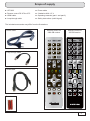
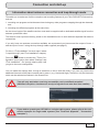
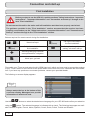
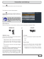
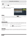
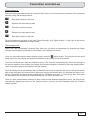
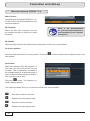
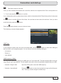
Operating manual part 1 Connection and start-up UFS 923 English Contents Safety instructions – important notes ....................................................................................................... 2 Scope of supply ........................................................................................................................................... 5 Connection and start-up ............................................................................................................................. 6 Front/rear view of the receiver (front flap open) .......................................................................................... 6 Inserting batteries into the remote control ................................................................................................... 8 Connecting the unit ..................................................................................................................................... 9 TV connection ............................................................................................................................................. 9 Audio connection ....................................................................................................................................... 10 Digital .......................................................................................................................................................................... 10 Analogue ..................................................................................................................................................................... 10 Connecting up the Video/DVD recorder .................................................................................................... 10 Information about antenna connection and loop-through mode................................................................ 11 First Installation ......................................................................................................................................... 12 Common Interface (CI) .............................................................................................................................. 47 Inserting the smart card and the CA module ............................................................................................................... 47 Troubleshooting ........................................................................................................................................ 48 Service ........................................................................................................................................................ 49 Technical Appendix ................................................................................................................................... 50 Advanced connection example ................................................................................................................. 50 Technical Specifications ............................................................................................................................ 51 Sat IF connection examples ...................................................................................................................... 52 Individual reception systems ....................................................................................................................................... Community antenna network systems (4 x Sat IF)...................................................................................................... Community antenna network systems (8 x Sat IF), multi-feed .................................................................................... Community antenna network systems (16 x Sat IF), multi-feed .................................................................................. Single cable systems................................................................................................................................................... 52 52 53 53 54 Connection examples for network functionality ......................................................................................... 56 DHCP (Receiver): OFF................................................................................................................................................ DHCP (Receiver): OFF................................................................................................................................................ DHCP (Receiver): OFF................................................................................................................................................ DHCP (Receiver): ON ................................................................................................................................................. 56 57 58 59 If you do not know the configuration of your satellite reception system, contact your specialist dealer for first installation of the receiver. Safety instructions – important notes These two pages contain important information about operation, installation location and connection of the unit. Read these instructions carefully before setting up the unit. Power cable Danger! Risk of death due to electric shock. Damp, sunlight, heat, naked flames Protect the unit against moisture, dripping and splashed water (do not place any filled objects such as vases on top of the unit). Do not place the unit close to a heater or expose it to direct sunlight and do not operate it in damp locations. Only use the unit in a moderate climate, not in tropical conditions! Place no naked flames such as candles on top of the unit! Cleaning There is a risk of fire! Disconnect the mains plug before cleaning the unit. Only use a dry cloth for cleaning and only clean the outer surface. Never open the casing of the unit. Batteries Make sure that the mains cable (power supply cable) is not damaged. Units with a damaged mains cable must be disconnected from the mains (unplug it at the socket) and repaired by an electrical specialist before setup. Only use the power pack supplied (if available). Touching the parts inside the unit carries a risk of death due to electric shock. Playing children Make sure that children do not push any objects into the ventilation slots. Risk of death due to electric shock. Warning! Earthing Warning! There is a risk of explosion! The antenna system must be earthed as specified or equipotentially bonded. EN 60728/11 and any national regulations must be complied with. Risk of voltage surges due to lightning strikes! Ventilation Warning! Mains voltage Only operate the unit at the specified mains voltage (indicated on the rear of the unit or on the external power pack). The unit may only be connected to the mains and turned on once it has been connected to the antenna and to the TV set or the cable network and PC. If the mains voltage is too high, there is a risk of fire. 2 If your unit was supplied with batteries (e.g. for the remote control), take care that the batteries are not exposed to excessively high temperatures, direct sunshine or fire. Exchange the batteries only with types that are identical or equivalent. Otherwise the batteries or the remote control may be damaged. Comply also with the safety instructions stated on the batteries: Do not cover The heat generated in this unit is adequately dissipated. However, the unit should never be installed in a cupboard or on shelves with inadequate ventilation. Never cover the cooling slots on the unit (e.g. with other equipment, magazines, tablecloths, clothing or curtains). Do not place any objects on top of the unit. Unless stated to the contrary in the "Connection and start-up" and "Installation” sections in the manual supplied, maintain a clearance of at least 10 cm above the unit, 2 cm to either side and 5 cm behind the unit, to allow unobstructed dissipation of the heat generated. There is a risk of fire! Safety instructions – important notes Repairs Ensure that any repairs to your unit are carried out by qualified personnel. Important Opening the unit and attempting to repair it yourself voids all warranty claims. Improper work on the unit may jeopardize the electrical safety of the unit. The manufacturer accepts no liability for accidents caused by the user opening the unit. Connections Incorrect wiring of the connections can lead to malfunctions or defects on the unit. Periods of extended absence, thunderstorms, mains socket accessibility In order to disconnect the unit from the mains completely, the mains plug must be unplugged from the wall socket! Therefore install the unit close to a mains socket and make sure that socket is accessible at all times, so that you can disconnect the unit from the mains if necessary. If you are away for an extended period, and during thunderstorms, always switch the unit off at the mains and unplug it from the socket. This also applies to the other equipment connected to the unit. Isolation from the cable network is also recommended. Note any timer programming (receiver) and turn the unit on again promptly before the recording time. Installation location All electronic equipment generates heat. However, the heating of this unit lies within the permissible range. Sensitive furniture surfaces and veneers may become discoloured by the effects of constant heat over time. The feet of the unit can also cause colour changes to treated furniture surfaces. If necessary, place the unit on a suitable stable and flat base. Electronic equipment must not be disposed of in domestic waste. According to directive 2002/96/EC OF THE EUROPEAN PARLIAMENT AND COUNCIL of 27 January 2003 on waste electrical and electronic equipment, it must be disposed of professionally. At the end of its service life, take this unit for disposal at a designated public collection point. Spent batteries are special waste. Do not throw spent batteries into your domestic waste; take them to a collection point for used batteries. 3 Safety instructions – important notes Product return/original packaging Please keep the original packaging in case you need to return the product at any time. The receivers are fragile due to their construction and are only adequately protected by the original packaging. If the receiver is not shipped correctly the guarantee/warranty on it will be voided. Fan/ventilation slots on the unit Make sure that the fan at the rear of the unit and the ventilation slots on the unit are not blocked or covered in any way. Otherwise the unit may overheat. Adjust the fan speed to the temperature conditions in the receiver. Warning! There is a risk of fire! Instructions on how to set the fan can be found in the chapter "Main Menu", "Settings", "Basic Settings", "Fan Settings". Switching the receiver off Before you switch disconnect the receiver from the mains, you must switch it to the standby mode by pressing the stand-by button (on/off) on the remote control. In standby mode, any changed or new data that are broadcast will be saved by the receiver. As soon as the receiver is in the standby mode, it can be disconnected from the mains at any time. You must not disconnect the receiver from the mains while it is in operation! This can lead to loss of data and corruption of the software. Other matters: The information in this operating manual was correct at the time of going to press. We reserve the right however to make changes at any time and without prior notice. If new software is released for your receiver, and this affects the information in the operating manual (e.g. changes to the menus and/or functions), if we believe it necessary we will make available a new operating manual for download under "www.kathrein.de". Make a note of the receiver's basic settings (these are set during first installation), so you can restore them if necessary! Please remember your duty of care towards your fellow human beings! Keep the manual for any questions that arise later, and if the building passes to another owner, pass it on to the new owner! 4 Scope of supply ■ UFS 923 ■ Power cable ■ Remote control RC 676 or 675 ■ 2 batteries AAA 1.5 V ■ HDMI cable ■ Operating manuals (part 1 and part 2) ■ Loop-through cable ■ Safety instructions (multi-lingual) The included accessories may differ from the illustrations. Power cable Remote control for 1000 GB version. Remote control for 250 GB version. Loop-through cable HDMI cable Batteries 5 6 2 OFF ON 100V-240V~ 50/60Hz max. 55W 10 11 1 Elektroschock-Gefahr! Nicht öffnen! 3 12 4 5 15 Manifactured under license from Dolby Laboratories. Dolby and the double-D symbol are trademarks of Dolby Laboratories. 13 6 14 16 17 VCR/AUX TV 18 7 9 R L 20 DIGITAL OUT Video AUDIO 21 KOMPONENTEN Pr Pb Y LNB1 IN 24 LNB 1 LOOP OUT LOOP THROUGH LNB 2 LOOP OUT LNB2 IN DiSEqC 1.2 950-2150MHz 14/18V max.400mA 22kHz IF INPUT 19 22 23 25 8 Connection and start-up Front/rear view of the receiver (front flap open) Connection and start-up Front view (flap open): Rear view: 1. Common Interface for two (CI+) CA modules for Pay-TV cards *) 10. On/Off switch **) 11. Mains power cable 2. One button each for ejecting the respective CA module 12. Fan 3. Record button 13. Infra-red sensor connection ***) 4. Stop button 14. Network connection (Ethernet) 5. USB 2.0 port 15. 2 x USB 2.0 ports (USB-A connectors) 6. 16-character alphanumeric display 16. HDMI connection 7. AUX button (call up Media Centre) 17. Scart socket for VCR/AUX connection 8. TV/R button 18. Scart socket for TV connection 9. Multifunction control 19. Electrical data stream output (SPDIF/Sony Philips Digital Interface Format) for Dolby Digital AC 3 audio 20. Optical data stream output (SPDIF/Sony Philips Digital Interface Format) for Dolby Digital AC 3 audio 21. Audio outputs (L/R) - cinch sockets 22. Video output (composite colour) 23. 3 x cinch connections for component outputs YUV labelled = Y/Pb/Pr 24. LNB 2-input (IN) and loop-through output (LOOP OUT) 25. LNB 1-input (IN) and loop-through output (LOOP OUT) *) CA modules and smart cards are not included with this product **) The unit is not fully disconnected from the mains (see the sections "Safety Instructions - Important Instructions" and "Periods of extended absence, thunderstorms, mains socket accessibility") ***) Accessories (optional) which can be purchased from your specialist dealer. HDMI = High-Definition Multimedia Interface (digital interface for video and audio) 7 Connection and start-up Inserting batteries into the remote control Remove the cover on the rear of the remote control. Insert the two batteries supplied into the remote control. Ensure correct polarity of the batteries; the + and – markings as indicated inside the battery compartment. Slide the cover back onto the housing until it locks in place. To open: Press lightly here and pull off backwards 8 Connection and start-up Connecting the unit If you do not know the configuration of your satellite reception system, contact your specialist dealer. Connect the Sat IF inputs on the receiver to the satellite reception system. Use coaxial cable with an F standard connector (see illustration on right). Conventional DiSEqC™ system TV Scart HDMI IF INPUT Video ON Y DiSEqC 1.2 950-2150MHz 14/18V max.400mA 22kHz LNB2 IN Manifactured under license from Dolby Laboratories. Dolby and the double-D symbol are trademarks of Dolby Laboratories. OFF TV DIGITAL OUT L LNB1 IN Pb LOOP THROUGH Elektroschock-Gefahr! Nicht öffnen! R 100V-240V~ 50/60Hz max. 55W VCR/AUX Pr AUDIO KOMPONENTEN LNB 2 LOOP OUT LNB 1 LOOP OUT TV connection Connect the satellite receiver (HDMI or alternatively TV Scart socket) and the TV set using a HDMI or Scart cable (see connection example above). 9 Connection and start-up Audio connection Digital There are two ways you can access the digital audio. HDMI The stereo audio is transmitted to your TV set via the HDMI interface. If your TV set also supports Dolby Digital, you can also receive the Dolby Digital audio via the HDMI interface (providing it is broadcast by the channel provider). On this issue refer to the operating manual for your TV set. SPDIF Dolby Digital output (electrical/visual) The SPDIF outputs are intended for the connection of a Dolby Digital system (see "Advanced connection example" in the technical appendix). Connect the SPDIF output (electrical or visual) and the Dolby Digital system using an appropriate cable. Analogue If you want to play the sound on your hi-fi system, connect the audio cinch sockets to the input sockets on the hi-fi system, using an appropriate cable (see "Advanced connection example" in the technical appendix). Connecting up the Video/DVD recorder Connect the satellite receiver (VCR/AUX Scart socket) to the video recorder/PVR using a Scart cable. To play back a DVD, i.e. output the signal from the DVR through the receiver on the TV set, the TV set must also be connected to the receiver with a Scart cable. This is required because the video signal from the VCR scart socket on the receiver is not looped through/redirected to the receiver's HDMI output. Tip! If you are recording via an external video/DVD recorder, remember not to operate the receiver during recording, otherwise all the on-screen displays will appear on your recording. If the receiver is started as a result of a timer recording, you do not receive an image on your TV set. You do not receive a TV image, i.e. the receiver is not started up, until you press the standby button (on/off). 10 SPDIF = Sony Philips Digital Interface Format (digital output for Dolby Digital AC 3 audio) Connection and start-up Information about antenna connection and loop-through mode To enable you to make use of all the reception and recording features of your Twin-DVR-HDTV Sat receiver, such as 1. recording one program and at the same time viewing any other program or zapping through the channels, and 2. recording two different programs at the same time, the two tuner inputs of the satellite receiver must each be supplied with a dedicated satellite signal from the antenna system/Sat outlet. The receiver tuner inputs are factory preset on the installation menu to work with two separate Sat antenna connections. If you only have one antenna connection available, we recommend you interconnect the output of tuner 1 and the input of tuner 2 using the loop-through cable supplied (see page 5). For this, in "First Installation" for tuner input 2 select "Looped through" (see "First Installation" chapter). button to access the "Tuner ConPress the figuration" menu option, then select "Settings" and "First Installation". Go through step-by-step until you get to the tuner configuration. You can make the settings here, though a restriction on this is that with tuner 2 you can only receive the additional channels of the plane currently set by tuner 1 (e.g. Horizontal High). Therefore, only the channels which can be selected are shown in the channel list. This will only work when receiving one satellite, not in multifeed reception! (Multifeed reception: simultaneous receipt of signals from more than one satellite) If you wish to operate your UFS 923 on a single-cable system, please refer to the connection example for single-cable systems (see "Technical Appendix", "Connection examples") 11 Connection and start-up First Installation Before you start to use the UFS 923, read the sections "Safety Instructions - Important Instructions", "Important Information" and "Connection and start-up" through to the item "First installation". Do not connect the unit to the mains until all installation work has been properly carried out. The guidance provided in the "First installation" section assumes that the receiver has been properly connected as per the "Safety Instructions - Important Information" and "Connection and start-up" sections through to the "First installation" section. Buttons required for remote control during first installation: ... (Red) Numerical input Go back one step in the first installation (Green) Call up the next step in the first installation Confirming the changed values/ setting; sub-menu call-up Selecting/changing individual menu parameters, navigation Abort input, go back First switch your TV set on and select the AV-/HDMI input on it which you have used to connect the receiver to your TV set. Switch on the receiver at the power switch on the rear of the unit. Undertake the first installation. If you have any questions or encounter problems, contact your specialist dealer. The following on-screen display appears: Tip! Always watch the bar at the bottom of the on-screen display. Messages here provide information on what to do next. buttons to select the desired menu language for your UFS 923 and confirm your selection using the button. The selected language is indicated with a check. The following languages are available: German, English, French, Italian, Spanish, Czech, Dutch, Polish, Turkish and Russian. Use the 12 Connection and start-up Press the (green) button to move to the next menu. The following on-screen display appears: Use the buttons here to select the basic settings for the video and audio output of the receiver to the TV set. For this, refer to the operating manual for your TV set and take care to select only those settings that your TV set can process. Video Output via Select the connection on the receiver to which you have connected your television. Either HDMI/YUV or SCART HDMI/YUV format TV format Here you can select the picture resolution that will be sent to the TV set. Either Here you can select the TV picture format. Either - 4:3 or - 1080p (resolution 1920 x 1080, full-screen images) - 16:9 - 1080i (resolution 1920 x 1080, half-screen images) - 720p (resolution 1280 x 720, full-screen images) or - 576p (resolution 720 x 576, full-screen images) - Automatically Force 576i (must be supported by the TV set otherwise you will not see a TV picture) Picture format Here you can select the type of screen display, depending on the setting of your TV aspect ratio: - TV aspect ratio “4:3”: Pan & Scan or Letterbox - TV aspect ratio “16:9”: Always 16:9 or Automatic You can only/only need to make this setting if you have selected the setting "Automatic" for "HDMI/ YUV Resolution". If for a program that is transmitted in the format 720 x 576 (standard TV), 13 Connection and start-up the original format is to be transmitted to the TV set, select the "On" setting. If the setting is "Off", the program may be automatically scaled-up to the HDTV format 720p by the receiver. HDCP (cannot be adjusted) Display of 4:3 broadcasts Here you can select the type of screen display mode for 4:3 broadcasts on a 16:9 TV set. Either TV Scart signal output Select the type of video signal at the TV Scart socket here. Select the signal that your TV set can process. - CVBS - Colour Video Baseband Signal or - RGB - Red/Green/Blue signal or - Y/C – S-Video signal (luminance/chrominance) VCR Scart signal output - Normal (Pillar Box) - Stretched (Full Screen) or - Zoom in (Pan & Scan) Select the type of video signal at the VCR Scart socket here. Select the signal that your external recorder can process. - CVBS - Colour Video Baseband Signal or Audio format via HDMI - Y/C – S-Video signal (luminance/chrominance) Here you can select the type of audio signal that is transmitted by the HDMI interface. Select the signal that your TV set can process: Autom. Dolby Digital output - Decoded PCM or - SPDIF format Autom. Dolby Digital output Here you can select whether the receiver should automatically select the Dolby Digital soundtrack (if this is transmitted). Important instruction for picture output using "YUV": The "YUV" output can be used only if "RGB" is not selected as the output signal for the TV Scart socket! In this case, select "Y/C" or "CVBS" as the output signal for the TV Scart socket 14 Here you can select whether the receiver should automatically output the Dolby Digital signal (if this is transmitted). Connection and start-up Press the (green) button to move to the next menu. The following on-screen display appears: The settings for the tuner configuration should be made by a specialist engineer for this reception system. Tip! If your receiver is connected as in the connection example (see illustration above), only one change/selection is necessary in the rest of the first installation. If you are not familiar with the details of your reception system, note the following: In many cases the satellite reception system is a DiSEqC™ 1.0 system. This type of system is preadjusted. Confirm the current on-screen displays using the (green) button. buttons the required satellites in the satellite selection (in Germany mostly ASTRA 19.2° East) and confirm the selection using the button. Confirm the rest of the onscreen displays during the first installation using the (green) button. You cannot damage your reception system during this process! If you do not receive a TV picture at the end of the first installation, You then select, using the contact your specialist dealer. You should perform the tuner configuration/make changes yourself only if you are fully familiar with the particulars of your reception system. 15 Connection and start-up You can set up the tuner configuration for the following types of reception systems: - DiSEqC™1.0 - DiSEqC™1.1 - Motorised antenna (DiSEqC™1.2/DiSEqC™1.3) - Simple LNB or - One Cable If your reception system is a single-cable system, continue from the item "Single-cable system" in this chapter. Before you start configuring the tuner, you must first perform both the "Tuner 2 type of connection" and "Signal configuration for Tuner 2” settings. Tuner 2 type of connection Select the type of connection for tuner 2 here. The currently selected setting is shown graphically in the connection example at the top left of the screen. Either: Separate: The second tuner input of the receiver (LNB2 IN) receives its own signal input (i.e. there is a direct connection between the antenna socket and tuner input 2). See example illustration on the right. Loop-through: The second tuner input on the receiver (LNB2 IN) receives the signal currently looped through from the tuner 1 looped through output. In this case, the second tuner can receive only the channel level currently being received by the first tuner. See example illustration on the right. See also "Information about antenna connection and loop-through mode" earlier in this chapter. 16 Connection and start-up Signal configuration for tuner 2 (only for "Separate" connection mode) Select the signal configuration for tuner 2 here. The currently selected setting is shown graphically in the connection example at the top left of the screen. Either: Same as tuner 1: Both tuners are connected to the same signal source. See example illustration on the right. Different to tuner 1: The two tuners are connected to different signal sources (separate cables from the LNB). See example illustration on the right. The following configuration options are available for: Tuner 2 type of connection "looped through": All settings are performed at tuner 1. The second tuner is fed from the looped through output of the first tuner. Tuner 2 type of connection "Separate" / Tuner 2 signal configuration "Same as tuner 1": All settings are performed at tuner 1. The settings for the second tuner are automatically taken from the first tuner. Tuner 2 type of connection "Separate" / Tuner 2 signal configuration "Different from tuner 1": All settings for both tuners must be performed separately. buttons to set the parameters "Tuner 2 type of connection" and "Signal configuration for tuner Use the 2" appropriate to the setting for your reception system. Continue as described in the first installation for the type of reception you selected. 17 Connection and start-up DiSEqC™1.0 Press the (green) button. The following on-screen display appears: Select satellites - tuner 1 Here, you can select up to four available satellites to be included in the signal on tuner 1. Select the satellites you want and confirm the your selection with the button. The selected satellites will be identified with a check. When you have completed all settings, press the 18 (green) button. Connection and start-up The following on-screen display appears: Satellite configuration - tuner 1 Here perform the settings for the first satellite for tuner 1. LNB Type: If your reception system does not have a Universal LNB, use the buttons to select the LNB types that are used in your reception system. You can choose from the following LNB types: - Universal, - Simple or - User-defined LNB frequency (MHz): You only need to specify this data if your LNB type is not "Universal LNB". The data required differ for the settings “Simple” and "User-defined". Refer to the documentation enclosed with your LNB or seek assistance from a specialist engineer. - Selection “Simple” LNB: Use the number pad to enter the LNB frequency - Selection “User-defined”: button to enter the required low, high and limit frequenPress the cies. The entry is made using the number keys DiSEqC™ position: - 1 of 4: For the first satellite of the tuner (item A on the system) - 2 of 4: For the second satellite of the tuner (item B on the system) - 3 of 4: For the third satellite of the tuner (item C on the system) - 4 of 4: For the fourth satellite of the tuner (item D on the system) 19 Connection and start-up DiSEqC™ repeat: Refer to the documentation for your reception system or seek assistance from a specialist engineer. The setting for how often the DiSEqC™ command must be repeated depends on the configuration of your reception system. - Off DiSEqC™ command is not repeated - 1 DiSEqC™ command is repeated once - 2 DiSEqC™ command is repeated twice - 3 DiSEqC™ command is repeated three times 22 kHz signal: You only need to specify this data if your LNB type is “Simple”. The 22 kHz signal is needed to switch LNBs in multi-feed reception and to switch between Low and High band. - On - Off Test transponder: Select the "Test Transponder" selection field. Here you can select a transponder for checking the signal strength bar and signal quality bar to see whether your settings are correct. When you have completed all settings for this satellite, press the (green) button. If you have selected more than one satellite (max. four) for tuner 1, the receiver will automatically skip to the settings for the second satellite. Now perform the settings for the second satellite, followed by the third and fourth satellites as required, in the same way as described for the first satellite. Once all settings for all the satellites that you selected have been completed, the receiver will automatically skip to the settings for the second tuner (assuming that for the second tuner you selected the type of connection "Separate" and set the signal configuration to "Different from tuner 1"). If this is the case, now make the settings for the second tuner in the same way as you did for the first tuner. Once you have completed the settings for both tuners and the satellites assigned to them, the receiver will automatically display the screen for the channel search. Continue the first installation with the "Channel search" section. 20 Connection and start-up DiSEqC™1.1 Press the (green) button. The following on-screen display appears: Select satellites - tuner 1 Here select up to a maximum of 64 satellites whose signals should appear at tuner 1. To do so, select the satellites you want and confirm the your selection with button. the The selected satellites will be identified with a check. When you have completed all settings, press the (green) button. 21 Connection and start-up The following on-screen display appears: Satellite configuration - tuner 1 Here perform the settings for the first satellite for tuner 1. LNB Type: If your reception system does not have a Universal LNB, use the buttons to select the LNB types that are used in your reception system. You can choose from the following LNB types: - Universal or - Simple or - User-defined LNB frequency (MHz): You only need to specify this data if your LNB type is not "Universal LNB". The data required differ for the settings “Simple” and "User-defined". Refer to the documentation enclosed with your LNB or seek assistance from a specialist engineer. - Selection “Simple” LNB: Use the number pad to enter the LNB frequency - Selection “User-defined”: button to enter the required low, high and limit frequenPress the cies. The entry is made using the number keys Uncommitted Switch Set the "Uncommitted Switches" here to match the configuration of your reception system. You can select "Off" or a value between "1" and "16" in single unit increments. 22 Connection and start-up DiSEqC™ repeat: The setting for how often the DiSEqC™ command must be repeated depends on the configuration of your reception system. Refer to the documentation for your reception system or seek assistance from a specialist engineer. - Off DiSEqC™ command is not repeated - 1 DiSEqC™ command is repeated once - 2 DiSEqC™ command is repeated twice - 3 DiSEqC™ command is repeated three times Position Select the selection field "Position". Set the "Position" here to match the configuration of your reception system. You can select "Off" or a value between "1" and "4" in single unit increments. Test transponder: Select the "Test Transponder" selection field. Here you can select a transponder for checking the signal strength bar and signal quality bar to see whether your settings are correct. When you have completed all settings for this satellite, press the (green) button. If you have selected more than one satellite (max. 64) for tuner 1, the receiver will automatically skip to the settings for the second satellite. Now perform the settings for the second satellite, followed by the other satellite selections, in the same way as described for the first satellite. Once all settings for all the satellites that you selected have been completed, the receiver will automatically skip to the settings for the second tuner (assuming that for the second tuner you selected the type of connection "Separate" and set the signal configuration to "Different from tuner 1"). If this is the case, now make the settings for the second tuner in the same way as you did for the first tuner. Once you have completed the settings for both tuners and the satellites assigned to them, the receiver will automatically display the screen for the channel search. Continue the first installation with the "Channel search" section. 23 Connection and start-up Motorised antenna (DiSEqC™1.2/DiSEqC™1.3) Press the (green) button. The following on-screen display appears: Select satellites - tuner 1 Here select up to max. 64 satellites whose signals should appear at tuner 1. To do so, select the satellites you want and confirm button. the your selection with the The selected satellites will be identified with a check. When you have completed all settings, press the 24 (green) button. Connection and start-up Motorised antenna (DiSEqC™1.2) The following on-screen display appears: Motor Control Here select the control type "DiSEqC™1.2". For this, refer to the documentation for your motorised antenna. Go to zero position Select the selection field "Go to zero posi- button to instruct the tion". Press the turntable to move to its zero position. Refer to the documentation for your motorised antenna or seek assistance from a specialist engineer. Set borders Select the selection field "Set borders". In this menu you can set the limits for your turntable. This is particularly necessary if the turntable has only a restricted range in which it can turn before striking an obstruction (such as a wall or tree). Press the button. The following onscreen display appears: The following buttons allow you to control the movement of the turntable: Start slow rotation to the west Rotate to the west step by step Stop the current movement Rotate to the east step by step Start slow rotation to the east Once you have reached the desired east / west limit, switch to the respective field "Set current position for "****" limit" and press the button to confirm. 25 Connection and start-up If you subsequently wish to delete the set limits, switch to the selection field "Reset limit positions" and press button to confirm deletion of the limits. You can then set new values for the limits. Once you have set all the limits, press the button. the Press the (green) button to move to the next menu. The following on-screen display appears: LNB Type: If your reception system does not have a Universal LNB, use the buttons to select the LNB types that are used in your reception system. You can choose from the following LNB types: - Universal or - Simple or - User-defined LNB frequency (MHz): You only need to specify this data if your LNB type is not "Universal LNB". The data required differ for the settings “Simple” and "User-defined". On this aspect, also refer to the documentation supplied with your LNB. - Selection “Simple” LNB: Use the number pad to enter the LNB frequency - Selection “User-defined”: button to enter the required low, high and limit frequenPress the cies. The entry is made using the number keys Stop on signal: Select the "Stop on signal" selection field. Here, you can select whether the motorised antenna should stop its rotary movement immediately on reception of a signal from the desired satellite. You can choose between "On" and "Off". 26 Connection and start-up Rotate antenna: Select the "Move motorised antenna" selection field. Here you can control the movements of the motorised antenna, using the following buttons: Start slow rotation to the west Rotate to the west step by step Stop the current movement Rotate to the east step by step Start slow rotation to the east Set the turntable so that both of the bars "Signal Strength" and "Signal Quality" on the right of the screen show the highest available percentage values. Test transponder: Select the "Test Transponder" selection field. Here you can select a transponder for checking the signal strength bar and signal quality bar to see whether your settings are correct. (green) button. The receiver will now save Once you have achieved the best reception signal, press the these values for this satellite and skips automatically to the setting for the next satellite. If you have selected more than one satellite for tuner 1, the receiver will automatically skip to the settings for the second satellite. Now perform the settings for the second satellite, followed by the other satellite selections, in the same way as described for the first satellite. Once all settings for all the satellites that you selected have been completed, the receiver will automatically skip to the settings for the second tuner (assuming that for the second tuner you selected the type of connection "Separate" and set the signal configuration to "Different from tuner 1"). If this is the case, now make the settings for the second tuner in the same way as you did for the first tuner. Once you have completed the settings for both tuners and the satellites assigned to them, the receiver will automatically display the screen for the channel search. Continue the first installation with the "Channel search" section. 27 Connection and start-up Motorised antenna (DiSEqC™1.3) Motor Control Here select the control type "DiSEqC™1.3". For this, refer to the documentation for your motorised antenna. My longitude Select the field "My Longitude" and use the number pad here to enter your actual longitude. Refer to the documentation for your motorised antenna or seek assistance from a specialist engineer. My latitude Select the "My Latitude" field and use the number pad to enter your current latitude. Go to zero position Select the selection field "Go to zero position". Press the zero position. button to instruct the turntable to move to its Set borders Select the selection field "Set borders". In this menu you can set the limits for your turntable. This is particularly necessary if the turntable has only a restricted range in which it can turn before striking an obstruction (such as a wall or tree). button. The following onPress the screen display appears: The following buttons allow you to control the movement of the turntable: 28 Start slow rotation to the west Rotate to the west step by step Stop the current movement Rotate to the east step by step Connection and start-up Start slow rotation to the east Once you have reached the desired east / west limit, switch to the respective field "Set current position for "****" limit" and press the button to confirm. If you subsequently wish to delete the set limits, switch to the selection field "Reset limit positions" and press button to confirm deletion of the limits. You can then set new values for the limits. Once you have set all the limits, press the button. the Press the (green) button to move to the next menu. The following on-screen display appears: LNB Type: If your reception system does not have a Universal LNB, use the buttons to select the LNB types that are used in your reception system. You can choose from the following LNB types: - Universal or - Simple or - User-defined LNB frequency (MHz): You only need to specify this data if your LNB type is not "Universal LNB". The data required differ for the settings “Simple” and "User-defined". On this aspect, also refer to the documentation supplied with your LNB. - Selection “Simple” LNB: Use the number pad to enter the LNB frequency - Selection “User-defined”: button to enter the required low, high and limit frequenPress the cies. The entry is made using the number keys 29 Connection and start-up Test transponder: Select the "Test Transponder" selection field. Here you can select a transponder for checking the signal strength bar and signal quality bar to see whether your settings are correct. (green) button. The receiver will now When you have completed all settings for this satellite, press the save these values for this satellite and skips automatically to the setting for the next satellite. If you have selected more than one satellite for tuner 1, the receiver will automatically skip to the settings for the second satellite. Now perform the settings for the second satellite, followed by the other satellite selections, in the same way as described for the first satellite. Once all settings for all the satellites that you selected have been completed, the receiver will automatically skip to the settings for the second tuner (assuming that for the second tuner you selected the type of connection "Separate" and set the signal configuration to "Different from tuner 1"). If this is the case, now make the settings for the second tuner in the same way as you did for the first tuner. Once you have completed the settings for both tuners and the satellites assigned to them, the receiver will automatically display the screen for the channel search. Continue the first installation with the "Channel search" section. 30 Connection and start-up LNB only Press the (green) button. The following on-screen display appears: Select satellites - tuner 1 Select the satellite whose signal is present button to on tuner 1, and press the confirm your selection. The selected satellite will be identified with a check. Once you have selected the required satellites, press the (green) button. The following on-screen display appears: Satellite configuration - tuner 1 Here perform the settings for the satellite for tuner 1. 31 Connection and start-up LNB Type: If your reception system does not have a Universal LNB, use the buttons to select the LNB types that are used in your reception system. You can choose from the following LNB types: - Universal or - Simple or - User-defined LNB frequency (MHz): You only need to specify this data if your LNB type is not "Universal LNB". The data required differ for the settings “Simple” and "User-defined". On this aspect, also refer to the documentation supplied with your LNB. - Selection “Simple” LNB: Use the number pad to enter the LNB frequency - Selection “User-defined”: button to enter the required low, high and limit frequenPress the cies. The entry is made using the number keys 22 kHz signal: You only need to specify this data if your LNB type is “Simple”. The 22 kHz signal is needed to switch LNBs in multi-feed reception and to switch between Low and High band. - On - Off Test transponder: Select the "Test Transponder" selection field. Here you can select a transponder for checking the signal strength bar and signal quality bar to see whether your settings are correct. When you have completed all settings for this satellite, press the (green) button. The receiver will automatically skip to the settings for the second tuner (assuming that for the second tuner you selected the type of connection "Separate" and set the signal configuration to "Different from tuner 1"). If this is the case, now make the settings for the second tuner in the same way as you did for the first tuner. Once you have completed the settings for both tuners and the satellites assigned to them, the receiver will automatically display the screen for the channel search. Continue the first installation with the "Channel search" section. 32 Connection and start-up One Cable Use the buttons to select "On" in the "Single-cable system used" line. buttons to switch Then use the to the "Single-cable system" selection field. The following on-screen display appears: Select the single-cable system used in your reception system: - EXR .../EXU ... For all Kathrein single-cable matrices - UAS 481 For the Kathrein single-cable LNB UAS 481 - User-defined For all single-cable systems not covered by either of the above specifications Continue as described in the first installation for the type of single-cable reception you selected. 33 Connection and start-up One Cable System – EXR .../EXU ... Press the (green) button. The following on-screen display appears: Select satellites - tuner 1 Here select up to max. two satellites whose signals should appear at tuner 1. Select the satellites you want and confirm the your button. selection with the The selected satellites will be identified with a check. When you have completed all settings, press the 34 (green) button. Connection and start-up The following on-screen display appears: Refer to the documentation supplied with your system for the settings for the SCRs, frequencies and any PIN assigned to the tuner. You will find there a printed list showing the assignment between the various SCRs and the respective transmission frequencies. You may not be able to freely select the PIN for protection of individual frequencies; this also may be listed in the documentation for the single-cable components. Please note also that multiple receivers cannot share the same frequencies / channels the receivers would interfere with each other. Do not assign the same frequencies / channels to tuner 1 and tuner 2. Protect the channel with a PIN: If your single-cable system allows the transmission frequency to be protected by inputting a PIN, this is the menu where that can be done. No other receiver can then use that transmission frequency unless the PIN is input. Select the setting "On". You then have the option of using the number pad to enter a PIN code (0-255) in the line underneath "Tuner 1 PIN code". Transmission channel for tuner 1: Select a free available transmission channel (SCR 0 - SCR 7). Transmission frequency for tuner 1: Select here one of the free available transmission frequencies. See example on the right (EXR 1581) assignment of a transmission channel to a transmission frequency. Perform the settings for the second tuner in the same way as for the first tuner. When you have completed all settings, press the (green) button. 35 Connection and start-up The following on-screen display appears: LNB type (settings): If your reception system does not have a Universal buttons to select the LNB LNB, use the types that are used in your reception system. You can choose from the following LNB types: - Universal or - Simple or - User-defined LNB frequency (MHz): You only need to specify this data if your LNB type is not "Universal LNB". The data required differ for the settings “Simple” and "User-defined". On this aspect, also refer to the documentation supplied with your LNB. - Selection “Simple” LNB: Use the number pad to enter the LNB frequency - Selection “User-defined”: button to enter the required low, high and limit frequenPress the cies. The entry is made using the number keys DiSEqC™ position: Select the selection field "DiSEqC™ position". Here set the "Position" for the satellite displayed on the screen, to match the configuration of your reception system. You can choose between: "1/1", "1/2" and "2/2", depending on whether at "Satellite selection" you selected one or two satellites. Test transponder: Select the "Test Transponder" selection field. Here you can select a transponder for checking the signal strength bar and signal quality bar to see whether your settings are correct. If no connection can be established to the single-cable system, check your settings (frequency and transmission channel) and if necessary call for expert help. (green) button. The receiver will now When you have completed all settings for this satellite, press the save these values for this satellite and skips automatically to the setting for the next satellite. If you have selected more than one satellite for tuner 1, the receiver will automatically skip to the settings for the second satellite. Now perform the settings for the second satellite in the same way as described for the first satellite. Once you have completed the settings for the satellites assigned, the receiver will automatically display the screen for the channel search. Continue the first installation with the "Channel search" section. 36 Connection and start-up Single-cable system - UAS 481 Press the (green) button. The following on-screen display appears: Select satellites - tuner 1 Here select the satellites whose signals appear at tuner 1. To do so, select the satellites you want and confirm the your selection with the button. When you have selected all the satellites you want, press the (green) button. The following on-screen display appears: 37 Connection and start-up Transmission channel for tuner 1: Select a free available transmission channel (SCR 0 - SCR 3). Transmission channel for tuner 2: Select a free available transmission channel (SCR 0 - SCR 3). When you have completed all settings for the satellite, press the display appears: (green) button. The following on-screen Test transponder: Select the "Test Transponder" selection field. Here you can select a transponder for checking the signal strength bar and signal quality bar to see whether your settings are correct. If no connection can be established to the single-cable system, check your settings (frequency and transmission channel) and if necessary call for expert help. When you have completed all settings for the satellite, press the (green) button. The receiver will automatically display the screen for the channel search. Continue the first installation with the "Channel search" section. 38 Connection and start-up Single-cable system - user-defined Press the (green) button. The following on-screen display appears: Select satellites - tuner 1 Here select up to max. two satellites whose signals should appear at tuner 1. To do so, select the satellites you want and confirm button. the your selection with the The selected satellites will be identified with a check. When you have completed all settings, press the (green) button. 39 Connection and start-up The following on-screen display appears: Refer to the documentation supplied with your system for the settings for the SCRs, frequencies and any PIN assigned to the tuner. You will find there a printed list showing the assignment between the various SCRs and the respective transmission frequencies. You may not be able to freely select the PIN for protection of individual frequencies; this also may be listed in the documentation for the single-cable components. Please note also that multiple receivers cannot share the same frequencies / channels the receivers would interfere with each other. Do not assign the same frequencies / channels to tuner 1 and tuner 2. Protect the channel with a PIN: If your single-cable system allows the transmission frequency to be protected by inputting a PIN, this is the menu where that can be done. No other receiver can then use that transmission frequency unless the PIN is input. Select the setting "On". You then have the option of using the number pad to enter a PIN code (0-255) in the line underneath "Tuner 1 PIN code". Transmission channel for tuner 1: Select a free available transmission channel (SCR 0 - SCR 7). Transmission frequency for tuner 1: Select here one of the free available transmission frequencies or use the number pad to input the required frequency. See example on the right (EXR 1581) assignment of a transmission channel to a transmission frequency. 40 Connection and start-up Perform the settings for the second tuner in the same way as for the first tuner. When you have completed all settings, press the (green) button. The following on-screen display appears: LNB type (settings): If your reception system does not have a buttons to Universal LNB, use the select the LNB types that are used in your reception system. You can choose from the following LNB types: - Universal or - Simple or - User-defined LNB frequency (MHz): Refer to the documentation enclosed with your LNB or seek assistance from a specialist engineer. You only need to specify this data if your LNB type is not "Universal LNB". The data required differ for the settings “Simple” and "User-defined". - Selection “Simple” LNB: Use the number pad to enter the LNB frequency - Selection “User-defined”: button to enter the required low, high and limit frequenPress the cies. The entry is made using the number keys DiSEqC™ position: Select the selection field "DiSEqC™ position". Here set the "Position" for the satellite displayed on the screen, to match the configuration of your reception system. You can choose between: "1/1", "1/2" and "2/2", depending on whether at "Satellite selection" you selected one or two satellites. Test transponder: Select the "Test Transponder" selection field. Here you can select a transponder for checking the signal strength bar and signal quality bar to see whether your settings are correct. If no connection can be established to the single-cable system, check your settings (frequency and transmission channel) and if necessary call for expert help. (green) button. The receiver will now When you have completed all settings for this satellite, press the save these values for this satellite and skips automatically to the setting for the next satellite. 41 Connection and start-up If you have selected more than one satellite for tuner 1, the receiver will automatically skip to the settings for the second satellite. Now perform the settings for the second satellite in the same way as described for the first satellite. Once you have completed the settings for the satellites assigned, the receiver will automatically display the screen for the channel search. Continue the first installation with the "Channel search" section. 42 Connection and start-up Channel search If you do not wish to perform a channel search, press the "Date and Time". If you want to perform a channel search, use the (green) button and continue with the section buttons to select "Yes". The following on-screen display appears: Country Select buttons you can select Using the whether the channels found after the search are to be sorted using a factory channel list for the selected country. Currently this feature is only available for Germany, Austria and Switzerland. Satellite and position buttons to select between the individual satellites you have set up, or the setting "All". Now use the If "All" is selected, all the individual satellites you have set up will be searched for new channels. Make sure your reception system is aligned to this/these selected satellite(s). 43 Connection and start-up Channel search mode Use the buttons to select the type of channels that are to be searched for. You have three options: - "free-to-air and encrypted" All channels are searched for - "only free" Only free-to-air channels are searched for - "only scrambled" Only encrypted channels are searched for To view encrypted channels you need an appropriate CA (Conditional Access) module and a valid smart card together with a valid subscription to a Pay-TV provider. Network Search Use the buttons (On/Off) to select whether a network search should be performed. If you set the "Network Search" to "Off", only the factory default transponders for the satellite(s) you previously selected will be searched for new as yet unsaved channels. If you set the "Network Search" to "On", the transponder network enables additional transponders that have not yet been stored to be located. They are then stored and scanned for new channels in the same way as the existing transponders. When you have completed all settings, press the (example): During the search you will see the following on-screen display (example): New channels found are identified by the suffix "NEW" (see screenshot example, right). Note: You can cancel the search at any time by pressing the button. After completion of the search, you will see the following on-screen display (example): button. The newly found Press the channels are added at the end of the existing complete list. 44 (green) button. The following on-screen displays appear TV channels found Radio channels found Connection and start-up Date and time Local UTC offset (time zone difference) Here you can select the local time offset to UTC (formerly GMT) (e.g. for Germany: + 1 hour). You can set the offset in 30 minute steps. The maximum offset is 11 hours and 30 minutes (+ and -). When you have made the settings, press the (green) button, to complete the first installation. 45 Connection and start-up Tip! On completion of a successful first installation (TV picture can be seen) we recommend having the receiver search for any available software update. It is a prerequisite that you have selected (included button to switch to the main menu. Use the buttons to select "Service Menu" and confirm by pressing the button. Use the buttons to select “Software update” and confirm again by pressing the button. The receiver will now automatically start to search for new software. For information on the rest in the selection) the satellite ASTRA 19.2° East in the first installation. Press the of the update process, please refer to the section "Main menu", "Service menu", "Software update" in these instructions. 46 Connection and start-up Common Interface (CI) Always follow the operating instructions from your Pay TV provider and the instructions supplied with the smart card and the CA (conditional access) module! Smart cards and CA modules are not included with this product! The cards and modules are issued by the respective Pay TV providers, and contain the subscriber data and details of the channels for which the subscriber has paid. These channels are always encrypted. Contact the Pay TV provider if you are interested in subscribing to a particular Pay TV channel. You are responsible for the use of the smart card in the CA The Smartcard sold by the Pay TV provider, specific to a particular encryption technology, is inserted into the CA module. Store your card and PIN code securely when not in use! Inserting the smart card and the CA module Inserting the CA module into the CI of the UFS 923 is suitable for insertion of two CA modules and is located on the front panel of the receiver (behind the flap). The CA module holds the smart card (chip contacts pointing downwards and towards socket strip) and is then inserted in the CI+ slot . The smart card should be inserted into the CA module without exerting excessive force. This also applies to inserting the CA module The Common Interface (CI) into the CI+ slot. Do not use a excessive force and follow the instructions supplied with the smart card and the CA module. To remove the CA module, press the corresponding ejection button keeping it straight. and pull it out towards the back, 47 Troubleshooting In the event of a malfunction, first check all the cable connections and operating states: 1. Receiver and TV set power plugs are connected to wall socket 2. Antenna cables on receiver input 3. Receiver and TV set correctly connected by a HDMI or Scart cable 4. Audio connections are made to Hi-Fi or Dolby Digital system as appropriate 5. Receiver and TV set (Hi-Fi/Dolby Digital system) are switched on (check power indicators) 6. Receiver is responding to remote control A selection of troubleshooting tips is offered below. Problem A "No signal!” warning appears on some or all channels The receiver no longer reacts to the remote control Cause Remedy Consult an antenna specialist to have it checked and repaired as necessary. Check the settings performed in the "Settings", "Antenna and satellites", "Tuner Configuration" menu, and change them if necessary. Check the batteries (see also "InsertThe batteries being used may be ing batteries in the remote control" in empty or have been inserted into the these instructions) battery compartment incorrectly. Set infrared code 1 as described in Receiver or remote control command the operating manual under “Main set may have been unintentionally menu settings”, “Basic settings”, changed “Setting the remote control code” Wrong time being displayed On "Settings" - "Date and Time" menu check summer time is enabled and "Summertime" setting is wrong. An change as necessary Use the power incorrect time was imported from the switch to switch the receiver off from reception signal the current channel, e.g. "Das Erste" or "ZDF", wait 10 seconds and then switch it back on The following channels cut out or "No or bad signal!" appears: Sport 1, Tele 5, HSE 24 and Sonnenklar TV DECT telephones operate on the same frequency as these channels. Consult your antenna specialist Interference may occur due to inadequate level or poor shielding of cable Black or blue screen, no on-screen displays Scart connection to TV deactivated Keep pressing the 0 button until the by accidentally pressing the 0 button TV picture reappears on-screen Network problem Check that the (cross-over) network cable is correctly connected at the Refer to your PC or network specialist PC and receiver (clicked home) 48 Service If, despite studying this operating manual, you still have questions about getting started with the unit or using it correctly, or if unexpected problems occur, please contact your specialist dealer. 49 Technical Appendix Advanced connection example Hi-Fi system TV Network PC/Laptop ESD 82 HDMI IF INPUT Video ON Y DiSEqC 1.2 950-2150MHz 14/18V max.400mA 22kHz LNB2 IN Manifactured under license from Dolby Laboratories. Dolby and the double-D symbol are trademarks of Dolby Laboratories. OFF TV L Pb R Pr VCR/AUX AUDIO KOMPONENTEN LNB 2 LOOP OUT External hard disk Dolby digital system DVR (VCR)/DVD 50 LNB1 IN LOOP THROUGH Elektroschock-Gefahr! Nicht öffnen! 100V-240V~ 50/60Hz max. 55W DIGITAL OUT LNB 1 LOOP OUT Technical Appendix Technical Specifications Type Article no./colour UFS 923/250 GB UFS 923/1000 GB 20210190/silver - 20210191/black 20210182/silver - 20210183/black RF section Sat IF band MHz 950-2150 Input level band dBμV 44-83 Modulation, FEC, demultiplexer DVB-S-/DVB-S2 standard Video resolution CCIR 601 (720 x 576 lines), 576p, 720p, 1080i, 1080p Video decoding MPEG2, MPEG4-compatible Input data rate S/N MSymb/s 2-45 (30 for DVB-S2/8PSK) dB > 53 TV system, audio Decoding AC 3, MPEG 1, Layers 1, 2 and 3 Sampling rate kHz 32/44,1/48 S/N dB > 65 Hard disk recorder Capacity Recording time 1) GB 250 1000 hrs Approx. 150 SDTV/approx. 50 HDTV Approx. 600 SDTV/approx. 200 HDTV Power supply Mains voltage Power consumption LNB supply (horiz./vert.) Control signal V/Hz 100-240/50-60 W max. < 55/typ. operation 21/standby < 0.5 V/mA 14/18; max. 400 kHz 22; DiSEqCTM1.0/-1.1/-1.2/-1.3; SCR one cable system Connections Sat IF input/output 4 x F socket TV/VCR connection 2 x Scart sockets Video output (analogue) 3 x Cinch socket (YPbPr)/1 x Cinch socket Video/audio output (digital) 1 x HDMI Audio output (analogue) 2 x Cinch sockets Audio output (digital) (optical/electrical) Standard fibre-optic cable (S/PDIF)/1 x Cinch socket Data interface Common Interface For 2 CI+/CI modules USB 3 x 2.0 Ethernet 1 RS 232 RJ 11 socket General Information Ambient temperature °C Max. +5 to +40 Unit dimensions (W x H x D) mm 435 x 69 x 303 kg 3.6 Weight 1) Depending on data rate and refresh rate 51 Technical Appendix Sat IF connection examples Individual reception systems 2x UAS 571 **) ESD../ESC.. Signal 1 Signal 2 Position OPTION UC1 Sat-ZF 950-2150 MHz EXR 21 Community antenna network systems (4 x Sat IF) 52 **) Overvoltage protection KAZ 11/KAZ 12 Technical Appendix Community antenna network systems (8 x Sat IF), multi-feed Community antenna network systems (16 x Sat IF), multi-feed **) Overvoltage protection KAZ 11/KAZ 12 53 Technical Appendix Single cable systems 54 **) Overvoltage protection KAZ 11/KAZ 12 Technical Appendix **) Overvoltage protection KAZ 11/KAZ 12 55 Technical Appendix Connection examples for network functionality DHCP (Receiver): OFF UFS 923 IF INPUT Video ON Y DiSEqC 1.2 950-2150MHz 14/18V max.400mA 22kHz LNB2 IN Manifactured under license from Dolby Laboratories. Dolby and the double-D symbol are trademarks of Dolby Laboratories. OFF TV DIGITAL OUT L Pb R Pr LOOP THROUGH Elektroschock-Gefahr! Nicht öffnen! 100V-240V~ 50/60Hz max. 55W VCR/AUX AUDIO KOMPONENTEN LNB 2 LOOP OUT IP-Adresse: IP address: 192.168.0.11 192.168.0.11 Gekreuztes Netzwerkkabel Crossed over network cable IP-Adresse: IP address: 192.168.0.10 192.168.0.10 PC/Laptop PC/Laptop 56 LNB1 IN LNB 1 LOOP OUT Technical Appendix DHCP (Receiver): OFF UFS 923 IF INPUT Video ON Y DiSEqC 1.2 950-2150MHz 14/18V max.400mA 22kHz LNB2 IN Manifactured under license from Dolby Laboratories. Dolby and the double-D symbol are trademarks of Dolby Laboratories. OFF DIGITAL OUT TV L LNB1 IN Pb LOOP THROUGH Elektroschock-Gefahr! Nicht öffnen! R 100V-240V~ 50/60Hz max. 55W VCR/AUX Pr AUDIO KOMPONENTEN LNB 2 LOOP OUT LNB 1 LOOP OUT TCP/IP-Adresse: TCP/IP address: 192.168.0.12 192.168.0.12 Network cable Netzwerkkabel Switch/HUB Network cable Netzwerkkabel PC/Laptop PC/Laptop TCP/IP-Adresse: TCP/IP address: 192.168.0.10 192.168.0.10 Network cable Netzwerkkabel PC/Laptop PC/Laptop TCP/IP-Adresse: TCP/IP address: 192.168.0.11 192.168.0.11 57 Technical Appendix DHCP (Receiver): OFF TCP/IP-Adresse: TCP/IP address: 192.168.0.12 192.168.0.12 TCP/IP-Adresse: TCP/IP address: 192.168.0.13 192.168.0.13 UFS 923 UFS 923 IF INPUT Video ON Y TV DIGITAL OUT L Pb R Pr IF INPUT DiSEqC 1.2 950-2150MHz 14/18V max.400mA 22kHz LNB2 IN Manifactured under license from Dolby Laboratories. Dolby and the double-D symbol are trademarks of Dolby Laboratories. OFF Video ON LNB1 IN 100V-240V~ 50/60Hz max. 55W VCR/AUX AUDIO KOMPONENTEN LNB 2 LOOP OUT TV DIGITAL OUT L Pb R Pr 100V-240V~ 50/60Hz max. 55W VCR/AUX AUDIO NAS system Network cable Netzwerkkabel DHCP-Server, DHCP server, Router router (z. B. Fritzbox) Fritzbox) (e.g. Netzwerkkabel Network cable 58 DiSEqC 1.2 950-2150MHz 14/18V max.400mA 22kHz LNB1 IN LOOP THROUGH Elektroschock-Gefahr! Nicht öffnen! LNB 1 LOOP OUT Y LNB2 IN Manifactured under license from Dolby Laboratories. Dolby and the double-D symbol are trademarks of Dolby Laboratories. OFF LOOP THROUGH Elektroschock-Gefahr! Nicht öffnen! Network cable Netzwerkkabel Netzwerkkabel Network cable PC/Laptop PC/Laptop PC/Laptop PC/Laptop TCP/IP address: TCP/IP-Adresse: 192.168.0.10 192 168 0 10 TCP/IP address: TCP/IP-Adresse: 192.168.0.11 192 168 0 11 KOMPONENTEN LNB 2 LOOP OUT LNB 1 LOOP OUT Technical Appendix DHCP (Receiver): ON UFS 923 IF INPUT Video ON Y DiSEqC 1.2 950-2150MHz 14/18V max.400mA 22kHz LNB2 IN Manifactured under license from Dolby Laboratories. Dolby and the double-D symbol are trademarks of Dolby Laboratories. OFF DIGITAL OUT TV L LNB1 IN Pb LOOP THROUGH Elektroschock-Gefahr! Nicht öffnen! R 100V-240V~ 50/60Hz max. 55W Pr AUDIO VCR/AUX KOMPONENTEN LNB 2 LOOP OUT LNB 1 LOOP OUT TCP/IP-Adresse: TCP/IP address: automatisch automatic NAS system DHCP-Server, Router DHCP server, router (e.g. (z. B. Fritzbox) Fritzbox) Network cable Netzwerkkabel Broadcast path Funkstrecke PC/Laptop PC/Laptop 59 Internet: www.kathrein.de 936.4046/-/ZWT/0211/e - Subject to change. KATHREIN-Werke KG • Anton-Kathrein-Strasse 1 - 3 • Postfach 10 04 44 • 83004 Rosenheim • Germany • Tel +49 8031 184-0 • Fax +49 8031 184-385