1
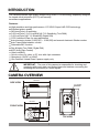
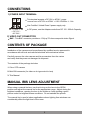
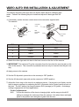
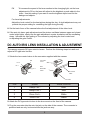
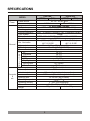
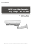
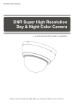
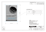
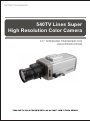
INSTRUCTION MANUAL
540TV Lines Super
High Resolution Color Camera
1/3'' INTERLINE TRANSFER CCD
HIGH RESOLUTION
ISSUE 1 - OCTOBER 2008
LIMITATION OF LIABILITY
THE INFORMATION IN THIS PUBLICATION IS BELIEVED TO BE
ACCURATE IN ALL RESPECTS, HOWEVER, WE CANNOT ASSUME
RESPONSIBILITY FOR ANY CONSEQUENCES RESULTING FROM
THE USE THEREOF. THE INFORMATION CONTAINED HEREIN IS
SUBJECT TO CHANGE WITHOUT NOTICE. REVISIONS OR NEW
EDITIONS TO THIS PUBLICATION MAY BE ISSUED TO
INCORPORATE SUCH CHANGES.
- ii -
WARNINGS AND CAUTIONS:
TO REDUCE THE RISK OF FIRE OR ELECTRIC SHOCK, DO NOT EXPOSE THIS PRODUCT TO RAIN OR
MOISTURE. DO NOT INSERT ANY METALLIC OBJECTS THROUGH THE VENTILATION GRILLS OR
OTHER OPENINGS ON THE EQUIPMENT.
CAUTION:
CAUTION
CAUTION: TO REDUCE THE RISK OF ELECTRIC SHOCK,
DO NOT REMOVE COVER(OR BACK).
NO USER-SERVICEABLE PARTS INSIDE.
REFER SERVICING TO QUALIFIED SERVICE PERSONNEL.
EXPLANATION OF GRAPHICAL SYMBOLS
The lightning flash with arrowhead symbol, within an equilateral triangle, is
intended to alert the user to the presence of uninsulated "dangerous voltage"
within the product's enclosure that may be of sufficient magnitude to constitute a
risk of electric shock to persons.
The exclamation point within an equilateral triangle is intended to alert the user to
the presence of important operating and maintenance (servicing) instructions in the
literature accompanying the product.
PRECAUTIONS
Safety -----------------------------------------
Installation -----------------------------------
Should any liquid or solid object fall into the cabinet,
unplug the unit and have it checked by the qualified
personnel before operating it any further.
Do not install the unit in an extremely hot or
humid place or in a place subject to excessive
dust, mechanical vibration.
Unplug the unit from the wall oulet if it is not going to
be used for several days or more. To disconnect the
cord, pull it out by the plug. Never pull the cord itself.
The unit is not designed to be waterproof.
Exposure to rain or water may damage the unit.
Allow adequate air circulation to prevent internal heat
build-up. Do not place the unit on surfaces (rugs,
blankets, etc.) or near materials(curtains, draperies)
that may block the ventilation holes.
Height and vertical linearity controls located at the
rear panel are for special adjustments by qualified
personnel only.
Cleaning -------------------------------------Clean the unit with a slightly damp soft cloth.
Use a mild household detergent. Never use
strong solvents such as thinner or benzine as
they might damage the finish of the unit.
Retain the original carton and packing
materials for safe transport of this unit in the
future.
- iii -
FCC COMPLIANCE STATEMENT
FCC INFORMATION : THIS EQUIPMENT HAS BEEN TESTED
AND FOUND TO COMPLY WITH THE LIMITS FOR A CLASS A DIGITAL
DEVICE, PURSUANT TO PART 15 OF THE FCC RULES. THESE
LIMITS ARE DESIGNED TO PROVIDE REASONABLE PROTECTION
AGAINST HARMFUL INTERFERENCE WHEN THE EQUIPMENT IS
OPERATED IN A COMMERCIAL ENVIRONMENT. THIS EQUIPMENT
GENERATES, USES, AND CAN RADIATE RADIO FREQUENCY
ENERGY AND IF NOT INSTALLED AND USED IN ACCORDANCE WITH
THE INSTRUCTION MANUAL, MAY CAUSE HARMFUL INTERFERENCE
TO RADIO COMMUNICATIONS. OPERATION OF THIS EQUIPMENT IN
A RESIDENTIAL AREA IS LIKELY TO CAUSE HARMFUL
INTERFERENCE IN WHICH CASE THE USER WILL BE REQUIRED TO
CORRECT THE INTERFERENCE AT HIS OWN EXPENSE.
CAUTION : CHANGES OR MODIFICATIONS NOT EXPRESSLY
APPROVED BY THE PARTY RESPONSIBLE FOR COMPLIANCE
COULD VOID THE USER'S AUTHORITY TO OPERATE THE EQUIPMENT.
THIS CLASS A DIGITAL APPARATUS COMPLIES WITH CANADIAN
ICES-003.
NORME NMB-003 DU CANADA.
CE COMPLIANCE STATEMENT
WARNING
This is a Class A product. In a domestic environment this product
may cause radio interference in which case the user may be required
to take adequate measures.
- iv -
IMPORTANT SAFEGUARDS
that may be connected to the equipment.
This will prevent damage to the equipment due
to Lightning or power-line surges.
1. READ AND RETAIN INSTRUCTIONS
Read the instruction manual before operating the
equipment. Retain the manual for future reference.
11. OVERLOADING
Do not overload wall outlets and extension cords
as this can result in a risk of fire or electric shock.
2. CLEANING
Turn the unit off and unplug from the power outlet
before cleaning. Use a damp cloth for cleaning.
Do not use harsh cleansers or aerosol cleaners.
12. SERVICING
Do not attempt to service the video monitor or
equipment yourself as opening or removing
covers may expose you to dangerous voltage
or other hazards. Refer all servicing to qualified
service personnel.
3. ATTACHMENTS
Do not use attachments unless recommended by
manufactured as they may affect the functionality of
the unit and result in the risk of fire, electric shock or
injury.
4. MOISTURE
Do not use equipment near water or other liquids.
5. ACCESSORIES
Equipment should be installed in a safe, stable
location. Any wall or shelf mounting accessory
equipment should be installed using the manufacture's
Instructions. Care should be used when moving
heavy equipment. Quick stops, excessive force, and
uneven surfaces may cause the equipment to fall
causing serious injury to persons and objects.
13. DAMAGE REQUIRING SERVICE
Unplug the equipment from the wall outlet and refer
servicing to qualified service personnel under the
Following conditions:
A. When the power supply cord or the plug has
been damaged.
B. If liquid has spilled or objects have fallen intothe
Unit.
C. If the equipment has been exposed to water or
other liquids.
D. If the equipment does not operate normally by
following the operating instructions, adjust only
those controls that are covered by the operating
instructions. Improper adjustment of other controls
may result in damage to the unit.
E. If the equipment has been dropped or the casing
Damaged.
F. When the equipment exhibits a distinct change in
performance.
6. VENTILATION
Openings in the equipment, if any, are provided for
ventilation to ensure reliable operation of the unit and
to protect if from overheating. These openings must
not be blocked or covered
7. POWER SOURCES
The equipment should be operated only from the type
of power source indicated on the marking label. If you
are not sure of the type of power supplied at the
installation location, contact your dealer. For
equipment designed to operate from battery power,
refer to the operating instructions.
8. GROUNDING OR POLARIZATION
Equipment that is powered through a polarized plug
(a plug with one blade wider than the other) will fit into
the power outlet only one way. This is a safety
feature. If you are unable to insert the plug fully into
the outlet, try reversing the plug. Do not defeat the
safety purpose of the polarized plug.
Alternate Warning: If the equipment is powered
through a three-way grounding-type plug, a plug
having a third (grounding) pin, the plug will only fit into
a grounding-type power outlet. This is a safety
feature. Do not defeat the safety purpose of the
grounding-type plug. If your outlet does not have the
grounding plug receptacle, contact your local
electrician.
9. CORD AND CABLE PROTECTION
Route power cords and cables in a manner to
protect them from damage by being walked on or
pinched by items places upon or against them.
10. LIGHTNING
For protection of the equipment during a lightning
storm or when it is left unattended and unused for
long periods of time, unplug the unit from the wall
outlet. Disconnect any antennas or cable systems
14. REPLACEMENT PARTS
When replacement parts are required, be sure the
service technician uses replacement parts specified
by the manufacturer or that have the same
characteristics as the original part.
Unauthorized substitutions may result in fire, electric
shock, or other hazards.
15. SAFETY CHECK
Upon completion of any service or repairs to the
equipment, ask the service technician to perform
safety checks to verify that the equipment is in proper
operating condition.
16. FIELD INSTALLATION
The installation of equipment should be made by a
qualified service person and should conform to all
local codes.
17. CAUTION - THESE SERVICING
INSTRUCTIONS ARE FOR USE BY QUALIFIED
SERVICE PERSONNEL ONLY. TO REDUCE THE
RISK OF ELECTRIC SHOCK DO NOT
PERFORM ANY SERVICING OTHER THAN THAT
CONTAINED IN THE OPERATING INSTRUCTIONS
UNLESS YOU ARE QUALIFIED TO DO SO.
18. Use certified/Listed Class 2 power supply transformer
Only.
-v-
TABLE OF CONTENTS
INTRODUCTION
1
CAMERA OVERVIEW
1
FUNCTION DESCRIPTION
2
CONNECTIONS
4
CONTENTS OF PACKAGE
4
MANUAL IRIS LENS ADJUSTMENT
4
VIDEO AUTO IRIS INSTALLATION & ADJUSTMENT
5
DC AUTO IRIS LENS INSTALLATION & ADJUSTMENT
6
BACK FOCUS ADJUSTMENT
7
ZOOM LENS BACK FOCUS ADJUSTMENT
8
TROUBLESHOOTING AND MAINTENANCE
8
SPECIFICATIONS
9
- vi -
INTRODUCTION
The camera provides high-quality images using SONY CCD technology especially designed
for closed-circuit television (CCTV) and security
surveillance applications.
Features:
High resolution and high performance 1/3" SONY Super HAD CCD technology
Excellent picture quality
540 lines(Color) of resolution
0.25 Lux(Color) / 0.01 Lux(B/W) @ F1.2 Sensitivity (True D&N)
0.25 Lux(Color) @ F1.2 Sensitivity (Digital D/N)
C/CS, backfocus cam for easy adjustment
Auto electronic shutter [1/60(1/50) ~ 1/100,000] and manual electronic Shutter modes
Auto Trace White balance modes
Selectable BLC function
Day & Night (True D&N / Digital D/N)
AGC (Auto Gain Control)
Video out(BNC)
Quick connect for video or DC lens with 4-pin connector
Operates in 12VDC or 24VAC
Use Certified / Listed Class 2 power supply only.
IMPORTANT : The user of this camera is responsible for checking and
complying with local, state, and federal laws and statutes concerning the
recording and monitoring of audio signals.
CAMERA OVERVIEW
120.0mm
SIDE VIEW
43.0mm
1/4-20UNC
1-32UNEF
56.0mm
FRONT VIEW
14.0mm
7.0mm
66.0mm
TOP VIEW
1
FUNCTION DESCRIPTION
- SIDE VIEW
1
1
Focus Adjusting Fixing Screw
2
Auto Iris Lens Connector
2
- REAR VIEW
1
AUTO
COLOR
D/N
1 IRIS LEVEL
2
2 FUNCTION SWITCH
3 POWER INPUT TERMINAL
5
~
DC 12V
AC 24V
3
4 POWER INDICATOR
5 VIDEO OUTPUT CONNECTOR
~
4
1) IRIS LEVEL
Adjust the DC-type auto iris lens for an optimum picture using this volume.
2) FUNCTION SWITCH
- E/I (on/off)
When set to the ON position, the electronic iris switch automatically varies the camera's shutter
to mimic auto-iris control, allowing fixed or manual iris lenses to be used in a wider range.
When this switch is set to ON, turn the F/F switch OFF.
2
- FF (on/off)
This function is used for removing flicker, when camera signal format does not coincide with
power source frequency being used.
- BLC (on/off)
This on/off switch controls backlight compensation. When set to ON, the camera will
automatically try to maintain proper exposure in the specific area even if the lighting level changes.
- AGC (on/off)
The auto gain control switch allows the video signals to maintain a constant level. This switch is
useful when using the camera at low-light levels and when lighting levels change over time.
For best low light conditions, this switch should set to ON.
- Day/Night (Auto/Color)
Use this switch to set the camera Day/Night mode Auto(ON) or Color(OFF)
Auto : D/N mode converse automatically (AGC must set to ON)
Color : Only Color
- A/I (DC/VIDEO)
Use this switch to set the auto iris type.
3) POWER INPUT TERMINAL
4) POWER INDICATOR
5) VIDEO OUTPUT CONNECTOR
3
CONNECTIONS
1) POWER INPUT TERMINAL
This terminal accepts a DC12V or AC24V power
source from a DC12V or AC24V +/-10% 60/50Hz +/- 1Hz
Use Certified / Listed Class 2 power supply only.
CLASS 2
+ DC 12V ~AC 24V~
In DC power, use the Adapter mode than DC 12V 500mA Capacity.
2) VIDEO OUT CONNECTOR
BNC : This BNC connector provides a 1.0Vp-p/75 ohms composite video Signal.
CONTENTS OF PACKAGE
Installation of the camera must be performed by qualified service personnel in
accordance with all local and national electrical and mechanical codes.
Carefully remove the color camera and its accessories from the carton
and verify that they were not damaged in shipment.
The contents of the package includes:
1. Color CCD camera
2. Mini-DIN connector (for video-or dc-type auto-iris lens)
3. This Manual
MANUAL IRIS LENS ADJUSTMENT
When using a manual iris lens, turn the iris ring on the lens to the OPEN
position and adjust the manual iris for the appropriate range. Adjust during the
brightest conditions, opening the lens to the minimum f-stop yielding a good
picture under the brightest scene conditions. Do not saturate the picture.
The manual iris is used in indoor applications where lighting from windows can
considerably affect the light level of the room.
4
VIDEO AUTO IRIS INSTALLATION & ADJUSTMENT
The camera supports video-type auto iris lenses which adjust to changing light
levels. Perform the following steps to install and adjust a video-type auto iris
lens.
1. If necessary, solder the lens control wires to the connector supplied with
The camera.
Connector
Cover
Rib
Pin 3
Automatic
Iris Lens
Pin 1
Pin 4
Heat
Shrinkable
Tubes
Iris Control
Pin 2
Cable
Connector
PIN
NAME
WIRE COLOR
1
Voltage +
2
Open
Red
_
3
Video
White
4
Ground
Black
2. Attach the video-type auto iris lens to the lens mount on the front of the camera.
3. IMPORTANT: The minimum Plug the connector from the lens into the auto iris jack on the
side of the camera. The connector is polarized and can only be inserted into the jack one
way.
4. Apply power to the camera.
5. Set the E/I dip switch (rear side on the camera) to OFF position.
6. Set the A/I dip switch (rear side on the camera) to VIDEO position.
7. Adjust the focus ring on the lens for an optimum picture. If a picture is not Visible, set the
lens for proper exposure by adjusting the ALC (Automatic Level Control) and the level on
the lens. The ALC setting can range between AVG (average) or PK (peak). A midrange
setting is appropriate for most applications.
For ALC adjustments:
AVG
To slow the reaction of the lens to changing light, set the range to the AVG
setting to average the video level from the camera. Use when there are bright
spots in the picture such as lights or glare from the sun.
5
PK
To increase the speed of the lens reaction to the changing light, set the lens
adjustment to PK so the lens will adjust to the brightest or peak object in the
video. Use this setting if you want to see the brightest object and not the
background objects.
For Level adjustments:
Adjust the level control for the best picture during the day. A night adjustment may not
provide the proper setting for controlling the light during the day.
8. Set the back focus of the camera before the final adjustment of the video level.
9. If the auto iris has a gain adjustment and the picture oscillates between open and closed
under bright lights, slowly turn the gain adjustment counter clockwise until the oscillating
stops. Increase the light getting to The camera by adjusting the level control and
re-adjusting the gain control.
DC AUTO IRIS LENS INSTALLATION & ADJUSTMENT
The camera supports DC-type auto iris lenses. Perform the following steps to install and
adjust a DC-type auto iris lens.
1. Solder the lens control wires to the connector supplied with the camera.
Connector
Cover
Rib
Pin 3
Automatic
Iris Lens
Pin 1
Pin 4
Heat
Shrinkable
Tubes
Iris Control
Pin 2
Cable
Connector
PIN
NAME
WIRE COLOR
1
Damp Coil -
Blue
2
Damp Coil +
Red
3
Drive Coil +
White
4
Drive Coil -
Green
2. Attach the DC-type auto iris lens to the lens mount on the front of the camera.
3. Plug the connector into the auto iris jack on the side of the camera. The connector is
polarized and can only be inserted into the jack one way.
6
4. Apply power to the camera.
5. Set the E/I dip switch (rear side on the camera) to OFF position.
6. Set the A/I dip switch (rear side on the camera) to DC position.
7. Adjust the auto iris lens for an optimum picture using the LEVEL volume on the rear side
of the camera.
BACK FOCUS ADJUSTMENT
For best results, perform back focus adjustments at night or while using a #6 or #8 welder's
glass in front of the lens. The focus of the camera will change slightly if the camera iris was
adjusted on a light scene, then changes to a dark scene. However, the camera will remain
in focus if the iris was focused on a dark scene and the scene lightens.
1. The lens should be mounted on the camera before applying power.
2. If a picture is visible, focus on the picture. If the picture is not visible, open the iris on the
lens. Open the lens as wide as possible by placing the welder's glass in front of the lens
and forcing the lens to automatically open.
3. When the iris is open to the widest point, re-adjust the focus for clear picture.
If a clear picture is not possible, set the focus ring to midrange.
4. Loosen the focus adjusting fixing screw.
5. Adjust the back focus ring for a clear picture.
6. Tighten the focus adjusting fixing screw.
7. Fine tune the focus with the focus ring on the lens.
8. Remove the welder's glass from in front of the lens.
9. Adjust the iris of the lens for the best picture quality.
7
ZOOM LENS BACK FOCUS ADJUSTMENT
The objective of back focusing a zoom lens is similar to that of a fixed focal length camera
except the back focus is also adjusted to maintain the focus when "zooming" the lens in and
out on a scene.
1. Choose an object at the farthest range set for viewing with a zoom lens.
2. Make sure the iris of the lens is wide open. Do this by adjusting the camera
at night or use a welders glass in front of the lens.
3. Adjust the focus to the stop on the far range.
4. Adjust the zoom on the lens to obtain the widest picture.
5. Loosen the focus adjusting fixing screw.
6. Adjust the back focus ring for the clearest picture.
7. Tighten the focus adjusting fixing screw.
8. Adjust the zoom on the lens to the far telephoto position.
9. Adjust the back focus ring for the clearest picture.
10. Adjust the zoom on the lens back to the widest picture.
11. Loosen the focus adjusting fixing screw.
12. Re-adjust the back focus for the clearest picture.
13. Tighten the focus adjusting fixing screw.
14. Repeat the previous steps as necessary to maintain a clear picture.
Throughout the entire zoom range.
TROUBLESHOOTING AND MAINTENANCE
TROUBLESHOOTING
If problems occur, verify the installation of the camera with the instructions in this manual and
with other operating equipment. Isolate the problem to the specific piece of equipment in the
system and refer to the equipment manual for further information.
PROBLEM
No video
AREA TO CHECK
1. Verify power is applied to all pieces of the equipment in the system.
The camera LED should be ON.
2. Verity that the video cables are connected correctly.
3. Verity that the lens cap has been removed from the lens and the iris
of the lens is open.
Video but no control Power down the system for one minute then re-apply power.
1. Adjust iris. 2. Check A/I connections.
Dark Video
PREVENTIVE MAINTENANCE
Preventive maintenance allows detection and correction of minor that faults before they
become serious and cause equipment failure.
Every three-month, perform the following maintenance.
1. Inspect all connection cables for deterioration or other damage.
2. Clean components with a clean damp cloth.
3. Verify that all the mounting hardware is secure.
8
SPECIFICATIONS
MODEL
Power
General
Connector
&
etc.
Power source
Power consumption
Image sensor
Total pixels
Scanning system
Scanning frequency
Sync. system
Electronic shutter
Resolution
True D&N
(NTSC)
(PAL)
Digital D/N
(NTSC)
(PAL)
DC 12V / AC 24V 10%
5.2 Watts
4.0 Watts
NTSC : 811(H) x 508(V) / PAL : 795(H) x 596(V)
2:1 interlace
NTSC : 15.734KHz(H) x 59.94Hz(V) / PAL : 15.625KHz(H) x 50Hz(V)
Internal
NTSC : 1/60 ~ 1/100,000 sec. / PAL : 1/50 ~ 1/100,000 sec.
540 TV Lines
Color ( 0.25 Lux) / BW(0.01Lux)
Color ( 0.25 Lux)
Min. illumination
@ F1.2, 50 IRE
@ F1.2, 50 IRE
1.0 Vp-p (75ohm, composite)
Video output
More than 50dB (AGC OFF)
S/N ratio
Dip switch
Camera Control
E/I
F
ON / OFF
U
Flickerless
ON / OFF
N
BLC
ON / OFF
C
AGC
ON / OFF
T
Day/Night
Auto / Color Fix
I
Auto
iris
lens
DC / VIDEO
O
N
White Balance
ATW Fixed
2-Pin Terminal block
Power input
Video output
BNC connector
4-Pin mini din jack (standard connection)
Auto iris output
Lens mount
C/CS mount (Selected through back focus)
Mounting hole
1/4''-20 UNC (top or bottom)
Operating temperature
+50
Operating humidity
0 ~ 96% (non-condencing)
66 (W) x 56 (H) x 120 (D)mm
External dimension
270g
255g
Weight
9
540TV Lines Super
High Resolution Color Camera
PRINTED IN KOREA
50302436A