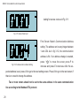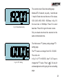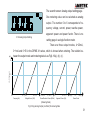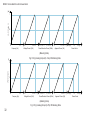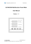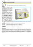
1
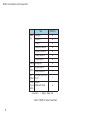
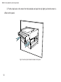
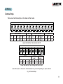
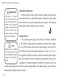
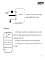
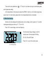
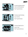
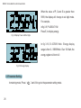
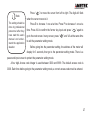
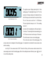
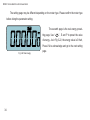
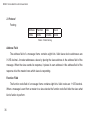
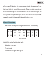
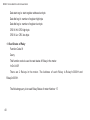
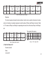
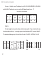
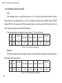
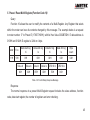
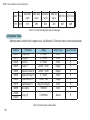
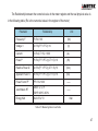
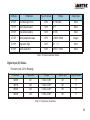
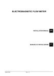
DPMS X1 Series Power Meter User’s Manual 1087-351 POWER INSTRUMENTS User Notes Page POWER INSTRUMENTS CopyRight © 2008 V1.0 This manual may not be reproduced in whole or in part by mimeograph or any other means, without permission of AMETEK. The information contained in this document is believed to be accurate at the time of publication, however, AMETEK assumes no responsibility for any errors which may appear here and reserves the right to make changes without notice. Please ask your local representative for the latest product specifications before ordering. I DPMS X1 Series Multi-function Power Meter Please read this manual carefully before installation, operation and maintenance of this product. The following symbols are used in this manual and on the meter to alert to danger or to prompt in the operating or set process. Danger symbol, Failure to observe the information may result in injury or death. Alert symbol, Alert to potential danger. Observe the information after the symbol to avoid possible injury or death. Dangerous Near dangerous position, Failure to observe the information may result in injury or death. Note Symbol, avoid result in meter damage or human injury or death. The instrument should be well grounded and powered off before maintenance. Installation and maintenance of the meter should be performed by qualified personnel that have appropriate training and experience with high voltage and current devices. II POWER INSTRUMENTS Content Contents.....…………………………………………………………………………………………………... Chapter 1 Introduction………………………………………………………………………………………1 1.1 Description................………………………………………………………………………………1 1.2 Application Area.........................……………………………………………………………………2 1.3 The DPMS X1 Series.............................................................…………………………………3 Chapter 2 Installation…………………………………………………………………………………………6 2.1 Appearance and Dimensions………………………………………………………………………6 2.2 Installation Method…………………………………………………………………………………8 2.3 Wiring………………………………………………………………………………………………11 Chapter 3 Operation and Setup……………………………………………………………………………20 3.1 Display and Keys…………………………………………………………………………………20 3.2 Metering Data Reading……………………………………………………………………………22 3.3 Meter parameter setting…………………………………………………………………………25 III DPMS X1 Series Multi-function Power Meter Chapter 4 Communication…………………………………………………………………………………33 4.1 Introduction of Modbus Protocol…………………………………………………………………33 4.2 Format of Communication…………………………………………………………………………37 4.3 Address Table………………………………………………………………………………………44 Appendix………………………………………………………………………………………………………49 Appendix A Technical Data and Specification………………………………………………………49 Appendix B Ordering…………………………………………………………………………………54 IV POWER INSTRUMENTS Chapter 1 Introduction 1.1 Description Powerful and Economical The DPMS X1 series power meter is design for single phase electrical value measurement using the latest microprocessor and digital signal processing technology. It can measure True-RMS Voltage, Current, Power, Reactive Power, Power Factor, Frequency and Energy. The meter can be used in high harmonic environments especially in middle and low voltage power systems, electric equipment, power system automation and factory automation. The measurements are available via digital RS485 communication port running Modbus TM Protocol. The meter also has I/O functions that combine the metering, monitoring, remote controlling and Analog output into one unit. Small Size & Easy Installation The DPMS X1 series was designed to standard DIN96*48 and reduced depth of 60mm. It is suitable for small cabinet installation in switch gear. It is asy to install on panels by using clips. 1 DPMS X1 Series Multi-function Power Meter Easy to Use A large character LCD with blue back light makes the display easy to read even under low light conditions. All the Value reading and parameter setting can be accessed by using 4 panel keys or the communication port. The parameters are protected in EEPROM, which will maintain its content after the meter is powered off. High Reliability and Safety Multi-isolation and immunity methods were adopted in the DPMS X1 design according to industry standards. The meter can be installed in hazardous industry areas. Also the meter was tested under IEC standards and EMC standards. The meter house was designed by using glass polymer which is durable and antifire. 1.2 Application Area The DPMS X1 series meter can be used to replace analog meters, panel meters, transducers and small RTUs in power distribution or power automation systems. As it adopted a true-RMS measuring method, the DPMS X1 meters are used for measuring voltage and current in high distortion nonlinear load systems, such as VVVF, Electric Ballast, Computer etc. 2 POWER INSTRUMENTS Power Distribution Automation Intelligent Electric Switch Gear Industry Automation Building Automation Energy Manage System Industry Apparatus 1.3 DPMS X1 Series DPMS X1 series power meters are used mainly in single phase or balanced three phase systems. The meter has measuring, communication and I/O functions. The DPMS X1 is a multi-function meter with communication port. For detail please refer to Table 1.1. 3 DPMS X1 Series Multi-function Power Meter Item Metering DPMS X1 Voltage V ● Current I ● Power P ● Reactive Power Q ● Apparent Power S ● Power Factor PF ● Frequency Hz ● Energy Energy Ep ● I/O Option Digital Input DI □ Relay Output RO □ AO Option 4~20mA or 0~1m or 0~5V □ Communication RS485 Modbus Protocol ● Function □ Option ● Blank NA Table1.1 DPMS X1 Series Power Meter 4 POWER INSTRUMENTS User Notes Page 5 DPMS X1 Series Multi-function Power Meter Chapter 2 Installation 2.1 Appearance and Dimensions 2.1.1 Appearance ② y Accuenerg ⑧ ③ V/ A P E ① ④ ⑤ Fig 2.1 Appearance 6 ⑦ ⑥ POWER INSTRUMENTS Part Name ① House ② Front Panel ③ Display Window ④ Key ⑤ Key Door ⑥ Clip Description Meter House is made of High Strength anti fire glass-polymer Front Part of the Meter LCD Display Window Used to change display and setting the parameters Used to protect key Mis-press Used fasten the meter on the panel ⑦ Input Terminal ⑧ Auxiliary Terminal Power supply, Voltage and Current Input Terminal Digital Input, Relay Output, Analog Output and Communication Terminal Table 2.1 Part Name of Meter 48.00 48.00 2.1.2 Dimension(mm) 60.00 96.00 71.00 Fig 2.2 Dimension 7 DPMS X1 Series Multi-function Power Meter 2.2 Installation Environment Note Before installation, please make sure that the environment satisfies The environment tem- the following conditions. perature, humidity and 1. Temperature position should be in The meter’s working temperature range is from -20c - 70c. If the the meter’s specifica- meter is used beyond this range, it will result in abnormal performance or tion range. even permanent damage to the meter. Meter’s storage range is from -40c - 85c. 2. Humidity Meter’s working humidity is from 0 - 95% non-condencing. 3. Position The meter should be installed in a dry and dust free environment and avoid heat, radiation and high electrical noise sources. Installation Steps Normally, the meter was installed on the switch board panel. 1. Cut a rectangular hole in the panel of the switch gear. The cutting size is in fig 2.3. 8 0.5 44± 0.0 POWER INSTRUMENTS cut Panel 90± 0.5 0.0 Fig 2.3 Panel Cutting 2. Remove the clips from the meter and insert the meter into the cut out hole from the front side. Panel EV 19 0 gy ener Accu Fig 2.4 Put the meter into square hole 9 DPMS X1 Series Multi-function Power Meter 3. Put the clips back on the meter from the backside and push the clip tightly so that the meter is affixed on the panel. Fig 2.5 Use the clips to fasten the meter on the panel 10 POWER INSTRUMENTS 2.3 Wiring Terminal Strips There are 2 terminal strips on the back of the meter. DIGITAL INPUTS AO RELAY OUTPUTS RS-485 DI1+ DI2+ DI3+ DI4+ DIC AO+ AO- R11 R12 R21 R22 A B S 9 10 11 12 13 14 15 16 17 18 19 20 21 22 Upper terminal strip: Communication and I/O POWER L 1 N 2 G 3 NC 4 VOLTAGE INPUT VL VN 5 6 CURRENT INPUT I2 8 I1 7 Lower terminal strip: Power, Voltage and Current Input Note: NC means No Connection. Certain terminals may not exist depending on options ordered. Fig 2.6 Terminal Strips 11 DPMS X1 Series Multi-function Power Meter DANGEROUS Onl y qua l i f i e d personnel should do the wire connection work. Make sure the power supply is off and all the wires are powerless. Failure to observe it may result in severe injury. Safety Earth Connection Before doing the meter wiring connection, please make sure that the switch Panel has a safety Earth system. Connect the meter safety earth terminal to the switch gear safety earth system. The following safety earth symbol is used in the user ’s manual. Auxiliary Power The auxiliary power supply of the meter is 85~264Vac (50/60Hz) Note Make sure the voltage of power supply is the same as what the meter needs for its auxiliary power. or 100~280Vdc. Typical power consumption is less than 2W. A regulator or a UPS should be used when the power supply varies too much. The terminals for the auxiliary power supply are 1, 2 and 3 (L, N, G). A fuse (typical 1A/250Vac) should be used in the auxiliary power supply loop. No.3 terminal must be connected to the safety earth system of the switchgear. An isolated transformer or EMI filter should be used in the auxiliary power supply loop if there is a power quality problem in the power supply. Typical Wiring of Auxiliary Power Supply is shown in Fig 2.7. 12 POWER INSTRUMENTS 1A FUSE 85~264Vac Power Supply Ground 1 L 2 N 3 G DPMS X1 The Best choice the wire of power supply could be AWG16~22 or 0.6~1.5mm2. Fig 2.7 Wiring of Power Supply Voltage Input A 400Vac option is suitable for a low voltage system that is less than Note The secondary of t h e P T c an not be shorted , otherwise it may cause the severe damage to the instrument . 480Vac. The voltage input should be directly connected to the meter terminal without the use of a PT. A fuse (typical 1A/250Vac) should be used in the voltage input loop. The wire gauge of the voltage input should be AWG16~22 or 0.6~1.5mm2. 13 DPMS X1 Series Multi-function Power Meter Note The CT loop should not be open circuit in any simultaneously when the power is on. There should not be any fuse or switch in the CT loop and one end of the CT loop should be connected to the ground. Current Input In a practical engineering application, CTs should be installed in the measuring loop. Normally the secondary of the CT is 5A. A CT of accuracy over 0.5% (rating over 3VA) is recommended and it will influence the measuring accuracy. The wire between the CT and meter should be as short as possible. The length of the wire may increase the error of the measurement. The wire gauge of the current input should be AWG15~16 or 1.5~2.5mm2. Wiring of Current Input Before Wiring, Please Make sure the voltage and current input of the meter corresponds to the power system measured. Single Phase Voltage and Current Input Wiring Diagram is shown in Fig 2.8 14 POWER INSTRUMENTS LINE L N K 5 VL Terminal Block 6 VN DPMS X1 7 I1 12~24Vac Fig 2.8 Current and Voltage Input OUT DI- DPMS X1 8 I2 LOAD Optal Couple DI+ + FIG 2.9 Digital Input Digital Input There are 4 Digital Inputs (Options) which require an external power supply. The Input terminals are DI1+(9), DI2+(10), DI3+(11), DI4+(12), DIC(13), as in Fig 2.9. The external power supply used for the Digital Input is from 16Vdc - 30Vdc. If the switch is far from the meter, the voltage of the power supply could be higher. The maximum current in the circuit should not be over 10mA. The wire gauge of Digital input should be AWG16~22 or 0.6~1.5mm2. 15 DPMS X1 Series Multi-function Power Meter Relay Output There are two additional relay outputs in the meter. The terminals are R11, R12 (16, 17) and R21, R22 (18, 19). These two relay outputs are used to remotely control an electric switch in power systems. The relay type is mechanical Form A contact with 3A/250V or 3A/30Vdc. An intermediate relay is recommended in the output circuit as in Fig 2.10. There are two relay output modes for selection, one is latching, and the other is momentary. For the latching mode, the relay 16 R11 Power Supply + DPMS X1 can be used to output two statues on or off. Mediate Relay R12 Control Output 17 For the momentary mode, the output of the relay changes from off to on for a period of Fig 2.10 Relay Output time Ton and than goes off. Ton can be set from 50- 3000ms. The wire gauge of the relay output should be between AWG22 (0.5mm2)~AWG16 (1.5mm2). 16 POWER INSTRUMENTS Alarm Output There is an alarm function in the DPMS X1 series meter. The alarm will be triggered when a metering parameter is over the limit value and over the setting time limit. The alarm can be related to relay output or LCD back-light flashing, Setting of the alarm is as follows. 1. Set the relay output mode as alarm. (DO?_MODE=2) 2. Assign metering parameter to alarm. (Refer Table 2.2) 3. Set alarm time limit. (Min time: 1s, Range: 0~255s) 4. Set alarm value limit. 5. Sign of the inequation. (0: parameter<Value limit, 1: parameter>Value limit) 6. Relate to relays. (0: RO1, 1: RO2) For the register of setting parameters please refer to 4.3 of this manual. Serial number versus alarming parameter is listed in Table 2.2. Number 0 means no parameter is assigned to alarm. Number Parameter 0 — — 1 Hz 2 U 3 I 4 P 5 Q 6 S 7 PF Table 2.2 Serial number versus alarming parameter 17 DPMS X1 Series Multi-function Power Meter Example: Alarming parameter: I, Alarm output relay: RO1, Time limit: 15s, Rating of CT1 of I: 200A, Value limit: 180A. The setting of alarm is as follows: 1. Set the relay output mode as alarm. DO?_MODE=2 2. The serial number of I is 3 from Table 2.2. 3. CT1=200, the equation converting between real value and register value is: Real value=(value in register × CT1 ÷ 5) ÷ 1000 If real value is 180A, the register value is 4500. 4. Time limit is 15s. The register value is 15. 5. The value is high limit, so the sign of in equation is 1 (great than). The alarm happens when register value>4500. 6. The alarm relating relay is RO1, so the RO select 0. After completing the above setting, the alarm will trigger RO1 and back-light flashing when the value of I is over 180A and lasts over 15 seconds. 18 POWER INSTRUMENTS Analog Output An Analog output (option) is provided in the DPMS X1 meter. Any one of the seven parameters could be selected as Analog Output. Refer to Chapter 3. Analog Output could be one of the following outputs, 4-20mA, 0-1mA and 0-5V VCC VCC Vout Load + - Vout + - R1 Load DPMS X1 R2 DPMS X1 Voltage Output Type R Current Output Type Fig 2.11 Analog Output Diagram Output Capacity: 4-20mA Max Load Resistance 750ohms 19 DPMS X1 Series Multi-function Power Meter 0-1mA Max Load Resistance 10kohms 0-5V Max Output Current 20mA Communication The communication port and protocol are RS485 and Modbus-RTU. The terminals of communication are A, B, and S (20, 21, 22). A is differential signal +, B is differential signal - and S connected to the shield of the twisted pair cable. Up to 32 devices can be connected on an RS485 bus. Use good quality shielded twisted pair cable, AWG22 (0.5mm2) or larger. The overall length of the RS485 cable connecting all devices can not exceed 1200m (4000ft). The meter is used as a slave device of a master like PC, PLC, data collector or RTU. The topology of RS485 net can be line, circle and star. A few points of recommendation for high quality communication are as follows: Good quality shielded twisted pair of cable AWG22 (0.6mm2) or larger is very important. The shield of each RS485 cable segment must be connected to ground at one end only. Make sure of the right connection at each point. Avoid T connections at each point. Keep cables away as much as possible from sources of electrical noise. 20 POWER INSTRUMENTS Chapter 3 Basic Operation and Setup 3.1 Display Panel and Keys There is one display panel and four keys on the front of the meter. All the display segments are illustrated in fig 3.1. ⑤ ② ⑥ ① ⑤ ③ ④ Fig 3.1 All Display Segments 21 DPMS X1 Series Multi-function Power Meter Number ① Display Data and Parameters Description Display metering data in metering mode. Display parameters in setting mode. Indicating Metering data unit. V and KV for Voltage, A for Current, KW for Power, KVar for Reactive Power, KVA for Apparent Power, KWH for Energy, PF for Power Factor, Hz for Frequency. ② Unit Label ③ Load Nature " ④ ⑤ Digital Input Parameter Label Indicator No.1 to No.4 switch indicate statues of DI1 to DI4 "SET" label is on when the meter is in the setting mode. One of the following label is also on. Addr for communication address, bps for Communication Rate (Bit per Second), pt1 for primary voltage, pt2 for secondary voltage, ct1 for primary current, ct2 for secondary ⑥ Communication state " : Capacitive Load, " current and " When " " : Inductive Load " for time of back light; " is on, it indicates that there is communication infor- mation between meter and master instrument. Table 3.1 Display Panel Description 22 POWER INSTRUMENTS There are four keys labelled as “ “, E, P and V/A. Use these four keys to read metering data and do parameter setting. All the descriptions in this manual are about the DPMS X1 which is a full function single phase power meter. For other meters, please refer to the corresponding function or description. 3.2 Meter Data Reading Normally, the meter displays the metering data, such as voltage, current, power etc. To read the metering data simply press the keys “P”, “E” and “V/A”. Press “V/A” to read voltage, current and frequency. The first screen: Display Voltage, U=220.3V, Inductive load, Communication Port Busy, DI1, DI2, DI3 and DI4 Open. Press “V/A”, to go to the second screen. Fig 3.2 Voltage Display 23 DPMS X1 Series Multi-function Power Meter The second screen: Display current. As in fig 3.3, I=498.7A. Press “V/A”, to go to the third screen. Fig 3.3 Current Display The third screen: Display frequency. As in Fig 3.4, F=50.00Hz. Press “V/A” again, to go back to the first screen. Fig 3.4 Frequency Display Press “P”, to display power related metering data. First screen: Display Power. In Fig 3.5, P=350.6KW, inductive Load, communication port busy, DI1 DI3 close and DI2 DI3 open. Fig 3.5 Power Display 24 Press “P”, to go to the second screen. POWER INSTRUMENTS The second screen: Display reactive power. In Fig 3.6, Q=-29.81KW, capacitive load. Press “P”, to go to the third screen. Fig 3.8 Power Factor Display The third screen: Apparent Power Display. In fig 3.7, S=837.1KVA Press “P”, to go to the forth screen. Fig 3.6 Reactive Power Display The forth screen: Display Power Factor. In fig 3.8, PF=-0.999. Press “P”, to go back to the first screen. Fig 3.7 Apparent Power Display 25 DPMS X1 Series Multi-function Power Meter When the value of P, Q and S is greater then 9999, the display will change to six digit mode. For example, in fig 3.9, P=23564.7 KW. Fig 3.9 Display Power with Six Digits Press E, to display energy. In fig 3.10, E=32768.9 Kwh. Energy display range is from 0 - 999999Kwh. Over 106 Kwh, the energy register will turn to 0. Fig 3.10 Energy Display 3.3 Parameter Setting In metering mode, Press “ 26 ” and V/A to go to the parameter setting mode. POWER INSTRUMENTS Note The setting should be done by professional personnel after they have read this user’s manual and understand the application situation. Press “ ” to move the cursor from left to right. The digit will flash when the cursor moves to it. Press E to increase 1 one at a time. Press P to decrease 1 one at a time. Press V/A to confirm the former key input and press “ go to the next screen. In any screen, press “ ” again to ” and V/A at the same time to exit the parameter setting mode. Before going into the parameter setting, the address of the meter will display for 3 seconds, then go to the parameter setting mode. There is a pass word input screen to protect the parameter setting mode. A four digit Access code integer is used between 0000 and 9999. The default access code is 0000. Each time before going to the parameter setting mode, a correct access code must be entered. 27 DPMS X1 Series Multi-function Power Meter Asking for access code as in Fig 3.11. Fig 3.11 Access Code Input First Screen: Meter’s Communication Address setting. The address can be any integer between 1 and 254. As in fig 3.12, the communication address is 84. If an address change is needed, Fig 3.12 Communication Address Setting press “ ” to move the cursor, press P to increase and press E to decreas. After the ex- pected address is set, press V/A to go to the next setting screen. Press V/A to go to the next screen if there is no need to change the address. Two or more meters should not be set to the same address in the same communication line according to the Modbus-RTU protocol. 28 POWER INSTRUMENTS The second screen: Baud rate setting page. Modbus-RTU 8 data bit, no parity, 1 start bit and 1 stop bit. Baud rate could be one of five values, 1200, 2400, 4800, 9600, 19200bps. In fig 3.13 Fig 3.13 Baud Rate Setting the baud rate is 19200bps. Press E to select baud rate. Press V/A to go to the next screen. Only one baud rate should be selected on the same communication line. The third screen: PT primary rating voltage PT1 setting page. The PT1 value is an integer from 100 - 500,000. The unit is volt. In fig 3.14, PT1=100000V, Use P, & E keys to Fig 3.14 PT1 Setting change the PT1 value. Press “ ” V/A key for acknowledgment and for going to the next setting page. 29 DPMS X1 Series Multi-function Power Meter The forth screen: PT secondary rating voltage PT2 setting page. The PT2 value is an integer from 100 - 400. The unit is volt. As in fig 3.15, PT2=400V, press P, E and “ Fig 3.15 PT2 Setting ” to change the value. Press V/A for acknowledgment and to go to the next setting page. Note: If there is no PT on the voltage input side, PT1 and PT2 should be the same and equal to the input rating voltage. The fifth screen: CT primary rating current Fig 3.16 CT1 Setting CT1 setting page. The CT1 value is an integer from 5 - 9999. The unit is Amp. As in fig 3.16, CT1=5000A, press P, E and “ ” to change the value. Press V/A for acknowledgment and to go to the next setting page. The sixth screen: The defult value of CT2 is 5 A. Fig 3.17 CT2 Setting 30 If the meter is a 1A option, CT2 should be 1A. POWER INSTRUMENTS The seventh screen: Analog output setting page. One metering value can be selected as analog output. The number 0 to 6 corresponds to frequency, voltage, current, power, reactive power, 3.18 Analog Output Setting apparent power and power factor. There is no setting page in a single function meter. There are three output modes, 4~20mA, 0~1mA and 0~5V in the DPMS X1 series, which is chosed when ordering. The relation between the output mode and metering data is as Fig3.19(a), (b), (c). (mA) ( AO Output ) 20 12 4 65 45 Frequecy(Hz) 0 PT1/CT1 Voltage/Current (V/A) 0 -PT1×CT1 PT1×CT1 PT1×CT1 Apparent Power (VA) Power/Reactive Power (W/Var) 0.5(C) 1.0 0.5(L) Power Factor (Metering Data) Fig 3.19(a) Anolog Output (4~20mA) VS metering Data 31 DPMS X1 Series Multi-function Power Meter (mA) ( AO Output ) 1 0.5 0 45 65 Frequecy (Hz) 0 PT1/CT1 Voltage/Current (V/A) -PT1×CT1 PT1×CT1 Power/Reactive Power (W/Var) 0 PT1×CT1 Apparent Power (VA) 0.5(C) 0.5(L) 1.0 Power Factor (Metering Data) Fig 3.19 (b) Analog Output (0~1mA) VS Metering Data (V) ( AO Output ) 5 2.5 0 45 65 Frequecy (Hz) 0 PT1/CT1 Voltage/Current (V/A) 0 -PT1×CT1 PT1×CT1 PT1×CT1 Apparent Power (VA) Power/Reactive Power (W/Var) (Metering Data) Fig 3.19 (c) Analog Output (0~5V) VS Metering Data 32 0.5(C) 1.0 0.5(L) Power Factor POWER INSTRUMENTS The eighth screen: Display back light “on” time setting page. The backlight will go to “off ” for the purpose of energy saving and component duraFig 3.20 Back light “on” time tion if the keys are untouched for a period of time. The “on” time can be set from 0 - 120 Minutes. The back light will always be “on” if the setting value is 0. As in fig 3.20, the setting time of the back light is 5 minutes. The back light will automatically go to “off” if there is no touch on the keys in 5 minutes. The ninth screen: Access code setting page. Fig 3.21 Access Code setting This is the last screen of the setting page. The access code can be changed in this setting page. It is important to remember the new access code after the setting. As in fig 3.21, the access code is 0001. Press the V/A key, let the access code be stored in the meter and go back to the first setting page. After all the setting has been finished, press “ A to exit the setting mode. ” and V/ 33 DPMS X1 Series Multi-function Power Meter The setting page may be different depending on the meter type. Please confirm the meter type before doing the parameter setting. The seventh page is the real energy presetting page, Use “ ” , E and P to preset the value of energy. As in Fig 3-22, the energy value is 0 Kwh, Press V/A to acknowledge and go to the next setting Fig 3-22 Real energy 34 page. Chapter 4 Communication POWER INSTRUMENTS 4.1 Introduction of Modbus Protocol The ModbusTM RTU protocol is used for communication in the meter. The data format and error checking method are defined in Modbus protocol. The half duplex query and respond mode is adopted in Modbus protocol. There is only one master device in the communication net. The others are slave devices, waiting for the query of the master. Only a master device can communicate with a slave device. The slave devices can not communicate with each other. They just respond to the query of a master device. 1. Transmission mode The mode of transmission defines the data structure within a frame and the rules used to transmit data. The mode is defined as follows which is compatible with Modbus RTU Mode*. Coding System 8 bit Start bit 1 bit Data bit Parity 8 bit None Stop bit 1 Error Checking CRC 35 DPMS X1 Series Multi-function Power Meter 2. Protocol Framing Address 8-Bits Function 8-Bits Data N×8-Bits Check 16-Bits Table 4.1 Data Framing Address Field The address field of a message frame contains eight bits. Valid slave device addresses are 0~255 decimal. A master addresses a slave by placing the slave address in the address field of the message. When the slave sends its response, it places its own address in this address field of the response to let the master know which slave is responding. Function Field The function code field of a message frame contains eight bits. Valid codes are 1~255 decimal. When a message is sent from a master to a slave device the function code field tells the slave what kind of action to perform. 36 POWER INSTRUMENTS Code 01 02 03 05 16 Meaning Read Relay output Read Digital Input Read Registers Control Relay Output Preset Multiple-Registers Action Status Obtain current status of Relay Output Status Obtain current status of Digital Input Obtain Current binary value in one or more registers Force Relay to a state of on or off Place specific binary values into a series of consecutive Multiple-Registers Fig 4.2 Function Code Data Field The data field is constructed using sets of two hexadecimal digits, from 00 to FF hexadecimal. The data field of messages sent from a master to slave devices contains additional information which the slave must use to take the action defined by the function code. This can include items like discrete and register addresses, the quantity of items to be handled, and the count of actual data bytes in the field. Check Field Check field is used in master and slave devices to find errors in the data transmitting process. There may be some error happening in a group of data when they are transmitted from one device to the other due to noise or other interference. The check field guarantees the device does not respond 37 DPMS X1 Series Multi-function Power Meter with error messages so as to improve system safety and efficiency. The CRC16 error check method is adopted in Modbus Protocol. 3. Error Check Method Messages include an error’s checking field that is based on a Cyclical Redundancy Check (CRC) method. The CRC field checks the contents of the entire message. It is applied regardless of any parity check method used for the individual characters of the message. The CRC field is two bytes, containing a 16 bit binary value. The CRC value is calculated by the transmitting device, which appends the CRC to the message. The receiving device recalculates a CRC during receipt of the message, and compares the calculated value to the actual value it received in the CRC field. If the two values are not equal, an error will be reported. The CRC is started by first preloading a 16-bit register to all 1’s. Then a process begins of applying successive 8-bit bytes of the message to the current contents of the register. Only the eight bits of data in each character are used for generating the CRC. Start and stop bits, and the parity bit, do not apply to the CRC. During generation of the CRC, each 8-bit character is exclusive ORed with the register contents. Then the result is shifted in the direction of the least significant bit (LSB), with a zero filled into the most significant bit (MSB) position. The LSB is extracted and examined. If the LSB was a 1, the register is then exclusive ORed with a preset, fixed value. If the LSB was 38 POWER INSTRUMENTS a 0, no exclusive OR takes place. This process is repeated until eight shifts have been performed. After the last (eighth) shift, the next 8-bit byte is exclusive ORed with the register current value, and the process repeats for eight more shifts as described above. The final contents of the register, after all the bytes of the message have been applied, is the CRC value. When the CRC is appended to the message, the low-order byte is appended first, followed by the high-order byte. 4.2 Format of Communication All the examples in this chapter are following the format of Table 4.3. (All data is in Hex). Addr Fun Data start reg hi 11H 03H 01H Data start reg lo Data #of regs hi Data #of regs lo CRC16 Hi CRC16 Lo 00H 00H 08H 47H 60H Table 4.3 Protocol Format In table 4.3, the meaning of each abbreviated word is, Addr: address of slave device Fun: function code Data start reg hi: start register address high byte 39 DPMS X1 Series Multi-function Power Meter Data start reg lo: start register address low byte Data #of reg hi: number of register high byte Data #of reg lo: number of register low byte CRC16 Hi: CRC high byte CRC16 Lo: CRC low byte 1. Read Status of Relay Function Code 01 Query This function code is used to read status of Relay in the meter. 1=On 0=Off There are 2 Relays in the meter. The Address of each Relay is Relay1=0000H and Relay2=0001H. The following query is to read Relay Status of meter Number 17. 40 POWER INSTRUMENTS Addr Fun Data start reg hi 11H 01H 00H Data start reg lo Data #of regs hi Data #of regs lo CRC16 Hi CRC16 Lo 00H 00H 02H BFH 5BH Table 4.4 Relay status query message Response The meter response includes the meter address, function code, quantity of data byte, the data, and error checking. An example response to read the status of Relay1 and Relay2 is shown in Table 4.5. The status of Relay1 and Relay2 is responding to the last 2 bits of the data. Relay1: bit0 Relay2: bit1. The content of the data is, Addr 11H Fun 01H Byte count Data 01H 02H CRC16 Hi CRC16 Lo D4H 89H Table 4.5 Relay status responds 7 6 5 4 3 2 1 0 0 0 0 0 0 0 1 0 LSB MSB (Relay 1 = OFF , Relay 2=ON) 2. Read the Status of DI Function Code 02 Query 1=On 0=Off 41 DPMS X1 Series Multi-function Power Meter There are 4 DIs in the meter. The Address of each DI is DI1=0000H, DI2=0001H, DI3=0002H and DI4=0003H. The following query is to read the 4 DI Status of meter Number 17. Table4.6 Read 4 DIs Query Message Addr Fun Data start reg hi Data start reg lo DI num hi DI num lo CRC16 Hi CRC16 Lo 11H 02H 00H 00H 00H 04H 7BH 59H Response The meter response includes its address, function code, quantity of data characters, the data characters, and error checking. An example response to read the status of 4 DIs is shown in Table 4.7. The status of each is responding to the last 4 bits of the data. DI1: bit0 DI2: bit1 DI3: bit2 DI4: bit3. Addr 11H Fun 02H Byte count Data 01H 03H CRC16 Hi CRC16 Lo E5H 49H Table 4.7 Read Status of DI 42 Data 7 6 5 4 3 2 1 0 0 0 0 0 0 1 MSB 0 1 LSB POWER INSTRUMENTS 3 Read Data (Function Code 03) Query This function allows the master to obtain the measurement results of the meter. Table 4.8 is an example to read the 3 measured data (F, V and I) from slave device number 17. The data address of F is 0000H, V1 is 0001H and V2 is 0002H. Addr Fun Data start reg hi 11H 03H 00H Data start reg lo Data #of regs hi Data #of regs lo CRC16 Hi CRC16 Lo 00H 00H 03H 07H 5BH Table 4.8 Read F, V, I Query Message Response The meter response includes the meter address, function code, quantity of data byte, data, and error checking. An example response to read F, V and I (F=1388H (50.00Hz), V=03E7H (99.9V), I=1386H (4.998A) is shown in Table 4.9. Addr Fun Byte count Data1 hi 11H 03H 06H 13H Data1 lo Data2 hi Data2 lo Data3 hi Data3 lo CRC16 hi CRC16 lo 88H 03H E7H 13H 86H 32H E8H Table 4.9 Read F, V and I Message 43 DPMS X1 Series Multi-function Power Meter 4. Control Relay (Function Code 05) Query This message forces a single Relay either on or off. Any Relay that exists within the meter can be forced to be either status (on or off). The address of Relays start at 0000H (Relay1=0000H Relay2=0001H). The data value FF00H will set the Relay on and the value 0000H will turn it off; all other values are illegal and will not affect that relay. The example below is a request to meter number 17 to turn on Relay1. Addr Fun DO addr hi 11 05H 00H DO addr lo 00H Value hi Value lo CRC16 Hi FFH 00H 8EH CRC16 Lo AAH Table 4.10 Control Relay Query Message Response The normal response to the command request is to retransmit the message as received after the Relay status has been altered. Addr Fun DO addr hi 11H 05H 00H DO addr lo 00H Value hi Value lo CRC16 Hi FFH 00H 8EH Table 4.11 Control Relay Response Message 44 CRC16 Lo AAH POWER INSTRUMENTS 5. Preset / Reset Multi-Register(Function Code 16) Query Function 16 allows the user to modify the contents of a Multi-Register. Any Register that exists within the meter can have its contents changed by this message. The example below is a request to meter number 17 to Preset E (17807.7KWH), with its Hex Value 0002B79DH. E data address is 0109H and 010AH. E register is 32bit or 4 byte. Addr Fun Data start reg hi Data start reg lo Data #of reg hi Data #of reg lo Byte count 11H 10H 01H 09H 00H 02H 04H Value hi Value lo Value hi Value lo CRC16 hi CRC16 lo 00H 02H B7H 9DH 7DH 0CH Table 4.12 Control Relay Response Message Response The normal response to a preset Multi-Register request includes the slave address, function code, data start register, the number of registers and error checking. 45 DPMS X1 Series Multi-function Power Meter Addr Fun Data start reg hi Data start reg lo Data #of reg hi Data #of reg lo CRC16 hi CRC16 lo 11H 10H 01H 09H 00H 02H 92H A6H Table 4.13 Preset Multi-Registers Response Message 4.3 Address Table Metering data is stored in the register area. Use Modbus 03 function code to read metering data. Address 0000H 0001H 0002H 0003H 0004H 0005H 0006H 0007H 0008H 0109H 010AH Parameter Frequency F Voltage V Current I Power P Reactive Power Q Apparent Power S Power Factor PF Load Nature RT AO Output Energy E Range 0 ~ 6500 0 ~ 65535 0 ~ 65535 -32768 ~ 32767 -32768 ~ 32767 0 ~ 65535 -1000~ 1000 76(L)/67(C)/82(R) 0~65535 Object Type Word Word Word Integer Integer Word Integer Word Word Type of Access R R R R R R R R R 0~9999999 Dword R Table 4.14 Metering data address table 46 POWER INSTRUMENTS The Relationship between the numerical value in the meter register and the real physical value is in the following table. (Rx is the numerical value in the register of the meter) Parameter Relationship Unit Frequency F F = Rx/100 (Hz) Voltage V U = Rx( PT1/PT2) /10 (V) Current I I=Rx( CT1/5) /1000 (A) Power P P =Rx( PT1/PT2) ( CT1/5) /10 (W) Reactive Power Q Q =Rx( PT1/PT2) ( CT1/5) /10 (Var) Apparent Power S S =Rx( PT1/PT2) ( CT1/5) /10 (VA) Power Factor PF P F =Rx/1000 —— Load Nature RT ASCII: L, C, R 52H:R 43H:C 4CH:L —— Energy Kwh K wh= Rx/10 Kwh Table 4.15 Measuring data convert table 47 DPMS X1 Series Multi-function Power Meter Parameter Setting Function code: 03 for Reading, 16 for Presetting Address 0101H 0103H 0104H 0105H 0106H 0107H 0108H Parameter Access Code Communication Address Baud Rate P T1 Lo PT1 Hi PT2 CT1 CT2 0102H Type of access R/W 0~9999 Object type Word R/W 1~254 Word R/W 0~4 Word R/W 100~500000 Dword R/W R/W R/W 100~400 5(1)~9999 5(1) Word Word Word 010BH Relay1 work Mode R/W 010CH Relay1 pulse width R/W 010DH Relay2 work Mode R/W 010EH Relay2 pulse width R/W 010FH AO VS Metering Data R/W Range 0 - L a t c h , 1 - M o m e n t a r y, 2-Alarm 50~3000 0-Latch,1-Momentary, 2-Alarm Word Word 50~3000 Word 0~6,0-Frequency,1-Voltage, 2-Current, 3-Power, 4-Reactive Power, 5-Apparent Power, 6-Power Factor Word Table 4.16 System parameter address 48 Word POWER INSTRUMENTS Address Parameter Type of access Range Object type 0110H LCD Back light Time R/W 0~120 (Min) Word 0111H Alarm object select R/W 0~7 Word 0112H Time limited setting R/W 0~255 0113H Alarm parameter value R/W -30000~30000 0114H Inequation Sign R/W 0:< 1:> Word 0115H Alarm relate RO R/W 0:RO1 1:RO2 Word Word Integer Table 4.16 System parameter address Digital Input (DI) Status: Function code: 02 for Reading Address 0000H Parameter DI1 Range 1=ON, 0=OFF Object type Bit Type of acess R 0001H DI2 1=ON, 0=OFF Bit R 0002H DI3 1=ON, 0=OFF Bit R 0003H DI4 1=ON, 0=OFF Bit R Table 4.17 Digital Input (DI) Address 49 DPMS X1 Series Multi-function Power Meter Relay Status and Control Function code: 01 for Reading, 05 for Controlling. Address Parameter Range Object type Type of access 0000H DO1 1=ON,0=OFF Bit R/W 0001H DO2 1=ON,0=OFF Bit R/W Table 4.18 Relay Address Note: 1. Object type: Bit - binary bit, word-unsigned integer of 16 bit, Integer - Signed integer of 16 bit, Dword -unsigned integer of 32 bit. 2. Type of Access: R - Read only, Digital input Relay status and Data are read by using function code 02, 01 and 03 respectively. R/W-Read and Write, Data is written by using function code 16 and control command is written by using function code 05. Writing to a read only field is forbidden. 3. Energy data is represented in 32 bit. Both high 16 bit and low 16 bit have successive address alone. The high 16 bit data should be multiplied by 65536 plus low 16 bit data to get the energy data in the master software. The unit is 0.1kwh or 0.1kvarh. It will be cleared to zero and start again when energy data accumulates to 1 x 10⁶kwh(kvarh). The energy register can be cleared or preset through the communication port. 50 POWER INSTRUMENTS Appendix A Technical Data and Specifications Input Ratings Voltage Input Voltage Rating -400V Option 400Vac 20% Over Range Frequency Range 45 to 65Hz Overload 2 times for continue 2500Vac for 1 Sec (None recurrence) Voltage Range Through PT 500KV highest at primary side PT Burden <0.2VA Measuring True-Rms 51 DPMS X1 Series Multi-function Power Meter Current Input Current Rating 5Amp, 20% Over Range Ordering on Special Rating Current Range Through CT 10000A at primary side Over Load 10A Continue, 100A/1sec (None Recurrence) CT Burden <0.5VA Measuring True-Rms Digital Input (DI) Optical Isolation Isolate Voltage 52 4000Vac rms Input Form Contact with Power Supply Input Resistance 2K ohm (typical) Input Voltage Range 16~30Vdc Close Voltage > 16Vdc Max Input Current 20mA POWER INSTRUMENTS Accuracy and Resolution Parameter Accuracy Resolution Voltage 0.5% 0.1% Current 0.5% 0.02% Power 1.0% 0.1% Reactive Power 1.0% 0.1% Apparent Power 1.0% 0.1% Power Factor 1.0% 0.1% Frequency 0.5% 0.01Hz Energy 1.0% Drift with Temp. Stability 0.1%/Year 0.1Kwh <100ppm/ ℃ 0.1%/Year 53 DPMS X1 Series Multi-function Power Meter Relay Output Output Form Mechanical Contact Contact Resistance 30m ohm@1A Max Break Voltage 250Vac, 30Vdc Max Break Current 3A Max Isolate Voltage 4000Vac rms Analog Output Output Range 4~20mA or 0~1mA or 0~5V Resolution 12bit Output Capability 54 4~20mA Max Resistance: 500Ω 0~5V Max Resistance: 10KΩ 0~1mA Max Resistance: 20mA POWER INSTRUMENTS Standard Measuring IEC60687 0.5 ANSI C12.16 Class10 IEC61036 class1 IEC61268 class2 Environment IEC 60068-2 Safety IEC 61557-2 EMC IEC61000-4/2-3-4-5-6-8-11 Dimension DIN43700 Suitable Condition Dimensions (mm) 96 ×48 ×60 (Cut 90 ×44) Protection Level IP54 (Front), IP20 (Cover) Weight (g) 400 Temperature -25℃~70℃ Humidity 0~95% Non-condensing Power Supply 85~264Vac or 100V~280Vdc Power 3W MAX 55 DPMS X1 Series Multi-function Power Meter Appendix B Ordering Information DPMS X1 * DI: 4 Digital Input s RO: 2 Form A Relay Outputs AO: 1 Analog Output DPMS X1 Fig 5.1 Ordering information 56 User Notes Page Experience the Power AMETEK Power Instruments 255 North Union Street, Rochester NY, 14605 U.S.A. 585-263-7700 Tel. 585-454-7805 Fax [email protected] www.ametekpower.com POWER INSTRUMENTS