1
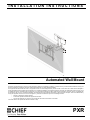
INSTALLATION INSTRUCTIONS
Automated Wall Mount
This device complies with part 15 of the FCC rules. Operation is subject to the following 2 conditions: (1) This device may not cause harmful interference, and (2) this
device must accept any interference received, including interference that may cause undesired operation.
This equipment has been tested and found to comply with the limits of a Class B digital device, pursuant to Part 15 of the FCC rules. These limits are designed to
provide reasonable protection against harmful interference in a residential installation. This equipment generates, uses and can radiate radio frequency energy, and if
not installed and used in accordance with the instructions, may cause harmful interference to radio or television communications. However, there is no guarantee that
the interference will not occur in a particular installation. If this equipment does cause harmful interference to radio or television reception, which can be determined by
turning the equipment off and on, the user is encouraged to try to correct the interference by one of the following measures:
•
•
•
Reorient or relocate the receiving antenna
Increase the separation between the equipment and receiver
Connect the equipment to an outlet on a circuit other than that to which the receiver is connected
Consult the dealer or an experienced radio/TV technician for help.
PXR
PXR
Installation Instructions
DISCLAIMER
Milestone AV Technologies, and its affiliated corporations and
subsidiaries (collectively, "Milestone"), intend to make this
manual accurate and complete. However, Milestone makes no
claim that the information contained herein covers all details,
conditions or variations, nor does it provide for every possible
contingency in connection with the installation or use of this
product. The information contained in this document is subject
to change without notice or obligation of any kind. Milestone
makes no representation of warranty, expressed or implied,
regarding the information contained herein. Milestone assumes
no responsibility for accuracy, completeness or sufficiency of
the information contained in this document.
WARNING: TO REDUCE THE RISK OF
BURNS, FIRE, ELECTRIC SHOCK, OR INJURY TO
PERSONS:
•
•
•
Chief® is a registered trademark of Milestone AV Technologies.
All rights reserved.
•
•
IMPORTANT SAFETY INSTRUCTIONS
•
•
•
•
WARNING alerts you to the possibility of
serious injury or death if you do not follow the instructions.
Always turn off power at source before putting on or
taking off parts.
Use this mounting system only for its intended use as
described in these instructions. Do NOT use
attachments not recommended by the manufacturer.
Never operate this mounting system if it has a
damaged cord or plug. If it is not working properly
during testing, return the mounting system to a service
center for examination and repair.
Keep the power cord away from heated surfaces.
Never operate the mounting system with the air
openings blocked. Keep the air openings free of lint,
hair, and the like.
Never drop or insert any object into any opening.
Do not use outdoors unless marked for outdoor use.
Route cords and cables as shown in the installation
instructions.
To disconnect, turn all controls to the off position, then
turn off power at source.
WARNING: RISK OF ELECTRIC SHOCK!
Connect this mounting system to a properly grounded outlet
only. See Grounding Instructions.
CAUTION alerts you to the possibility of
damage or destruction of equipment if you do not follow the
corresponding instructions.
WARNING: FAILURE TO READ AND
FOLLOW THE FOLLOWING INSTRUCTIONS CAN RESULT
IN SERIOUS PERSONAL INJURY, DAMAGE TO EQUIPMENT
OR VOIDING OF FACTORY WARRANTY. It is the installer’s
responsibility to make sure all components are properly
assembled and installed using the instructions provided.
When using an electrical mounting system, basic precautions
should always be followed, including the following:
READ ALL INSTRUCTIONS BEFORE USING THIS
PRODUCT!!!!
DANGER: TO REDUCE THE RISK OF
CAUTION: Changes or modifications to this
unit not expressly approved by the manufacturer can void the
units FCC compliance rating and make the unit illegal to
operate.
WARNING:
Failure to provide adequate
structural strength for this component can result in serious
personal injury or damage to equipment! It is the installer’s
responsibility to make sure the structure to which this
component is attached can support five times the combined
weight of all equipment. Reinforce the structure as required
before installing the component.
WARNING:
Exceeding the weight capacity
can result in serious personal injury or damage to equipment!
The weight capacity of the PXR varies based on the depth of
the display (including spacers), but must not exceed 150 lbs
(68.0). It is the installer’s responsibility to make sure the weight
of all components attached to the PXR meet this criteria.
NOTE: This system has no user serviceable parts.
ELECTRIC SHOCK:
1.
2
Always turn off power at source before cleaning.
--SAVE THESE INSTRUCTIONS--
Installation Instructions
PXR
TABLE OF CONTENTS
DISCLAIMER . . . . . . . . . . . . . . . . . . . . . . . . . 2
TABLE OF CONTENTS . . . . . . . . . . . . . . . . . 3
DIMENSIONS . . . . . . . . . . . . . . . . . . . . . . . . . 4
LEGEND . . . . . . . . . . . . . . . . . . . . . . . . . . . . . 6
TOOLS REQUIRED FOR INSTALLATION . . 7
SET-UP AND CONFIGURATION WITH
DISPLAY ATTACHED . . . . . . . . . . . . . . 21
Running LEARN MODE . . . . . . . . . . . . . 21
Saving a Preset . . . . . . . . . . . . . . . . . . . 22
Final Attachment to Wall Mounting
PARTS . . . . . . . . . . . . . . . . . . . . . . . . . . . . . .7
Bracket . . . . . . . . . . . . . . . . . . . . . . . . . 23
SITE PREPARATION . . . . . . . . . . . . . . . . . .8
ADVANCED SETTINGS . . . . . . . . . . . . . . . 23
Locating and Preparing a Mounting Site . .8
IR Repeat Conditions . . . . . . . . . . . . . . 23
Power Requirements and Wiring . . . . . . .8
Heavy Screen Mode . . . . . . . . . . . . . . . 23
Grounding Instructions . . . . . . . . . . . . . . . 8
Emergency Service Extend. . . . . . . . . . . 23
PXR DIAGRAM . . . . . . . . . . . . . . . . . . . . . . . 9
PROGRAMMING VIA RS485 . . . . . . . . . . . 24
Setting PXR Address
. . . . . . . . . . . . . . 24
Installing to a Wood Stud Wall . . . . . . . . 10
RS-485 Commands
. . . . . . . . . . . . . . . 24
Installing to a Solid Concrete Wall . . . . . 12
Calculating a Check Digit Code . . . . . . . 24
Installing in an In-Wall Box . . . . . . . . . . . 14
Common Commands . . . . . . . . . . . . . . . 25
Arm Engagement . . . . . . . . . . . . . . . . . . 16
Get Status (0x01) Command . . . . . . . . . 25
Installing IR Sensor . . . . . . . . . . . . . . . . . 17
Get System Status (0x2F). . . . . . . . . . . . 26
SET-UP AND TESTING CONFIGURATION 17
PXR Blink Codes . . . . . . . . . . . . . . . . . . 26
Running Learn Mode (Test) . . . . . . . . . . . 17
Fault Conditions . . . . . . . . . . . . . . . . . . . 26
Attach Interface Brackets to Display . . . . 18
RS-485 Terminal Block Wiring . . . . . . . . 28
Hanging Display on PXR . . . . . . . . . . . . 19
IR Receiver Pinout . . . . . . . . . . . . . . . . . 28
INSTALLATION . . . . . . . . . . . . . . . . . . . . . . . 9
Cable Management . . . . . . . . . . . . . . . . . 20
3
PXR
Installation Instructions
DIMENSIONS
20.45
519.5
6.36
BACK
5.47
17.44
442.9
8.06
9.19
233.4
CENTER OF INTERFACE
TO MOUNTING HOLES
45° PAN LEFT
45° PAN RIGHT
.739
18.8
4.75
120.6
16.00
406.4
26.96
684.7
MAX. DISTANCE
FROM WALL
29.25
743.0
19.18
487.2
17.72
450.0
MAX.
VERT.
PATTERN
9.93
252.2
TO CENTER
27.56
700.0
MAX. HORIZ. PATTERN
4
.50
12.7
L/R SHIFT
4.50
114.3
MIN. DISTANCE
FROM WALL
2.03
51.6
12°
MAX. TILT
18.50
469.9
18.89
479.9
3.45
87.6
DIMENSIONS:
INCHES
[MILLIMETERS]
Installation Instructions
PXR
DIMENSIONS...continued
PRE-INSTALL SETUP FOR WALL MOUNTING
ARMS AND HEAD UNIT HIDDEN FOR CLARITY
MECHANICAL
MOUNTING PATTERNS:
WEIGHT CAPACITY:
EXTENSION:
29.50
749.3
PAN:
TILT:
4.88
123.8
NOISE LEVEL*
MAX SPEED*
5.10
129.5
MINIMUM (H x V)
200 X 100
MAXIMUM (H x V)
700 X 450
Varies dependent on depth of display--150 LB (68.0 KG) MAX
UP TO 27" AWAY FROM THE WALL
MINIMUM: 4.5" FLUSH MOUNTED, 1.0" WHEN RECESSED
USING A PAC 502
UP TO 45° TO THE LEFT AND RIGHT (90° TOTAL)
UP TO 12° DOWN (DEPENDING ON SCREEN SIZE)
52 dBA @ 36" WITH MAX LOAD
EXTEND/RETRACT:
.75" / SEC
PAN:
4.5° / SEC
TILT:
3.0° / SEC
POWER
MAX CONSUMPTION: 85 W
STANDBY CONSUMPTION: <2 W
POWER SUPPLY: 100-250 VAC, 50/60 Hz
12.40
315.0
FEATURES
PRESET HOME POSITION
4 PROGRAMMABLE POSITIONS
CONTROLLABLE VIA RS485 COMMUNICATIONS
BUILT-IN IR REPEATER (TRANSMITTER NOT INCLUDED)
12.15
308.5
7.38
187.3
SIMULTANEOUS AXIS MOVEMENT
DIMENSIONS
10.70
271.8
PACKAGE SIZE
PACKAGE WEIGHT
PRODUCT SIZE
PRODUCT WEIGHT
3.62
91.9
KEEP THESE AREAS CLEAR. DO NOT PUT OUTLETS,
CORDS, OR ANY OTHER DEVICES IN THESE AREAS
THIS AREA IS THE RECOMMENDED LOCATION TO
PLACE AN OUTLET AND FEED DATA LINES.
36" x 24" x 7.75"
APPROX. 80 LB
29.25" x 19.2" x 4.5"
APPROX. 65 LB
* PERFORMANCE MAY VARY
SEE PAC502 INSTRUCTIONS FOR INSTALLING IN AN IN-WALL BOX
DIMENSIONS:
INCHES
[MILLIMETERS]
TO VERIFY DISPLAY IS COMPATIBLE WITH PXR
Method 1
1.
Go to www.chiefmfg.com.
2.
Select manufacturer and model of display in MountFinder™.
3.
Click "Search".
NOTE: If PXR is listed in search results, display is compatible with PXR.
Method 2
1.
If access to www.chiefmfg.com is not available, verify that the display mounting pattern is less than 700mm x 450mm, and
use the chart below to determine if display is compatible.
NOTE: Not all displays that meet this criteria will be compatible with the PXR.
5
PXR
Installation Instructions
LEGEND
6
Tighten Fastener
Pencil Mark
Apretar elemento de fijación
Marcar con lápiz
Befestigungsteil festziehen
Stiftmarkierung
Apertar fixador
Marcar com lápis
Serrare il fissaggio
Segno a matita
Bevestiging vastdraaien
Potloodmerkteken
Serrez les fixations
Marquage au crayon
Loosen Fastener
Drill Hole
Aflojar elemento de fijación
Perforar
Befestigungsteil lösen
Bohrloch
Desapertar fixador
Fazer furo
Allentare il fissaggio
Praticare un foro
Bevestiging losdraaien
Gat boren
Desserrez les fixations
Percez un trou
Phillips Screwdriver
Adjust
Destornillador Phillips
Ajustar
Kreuzschlitzschraubendreher
Einstellen
Chave de fendas Phillips
Ajustar
Cacciavite a stella
Regolare
Kruiskopschroevendraaier
Afstellen
Tournevis à pointe cruciforme
Ajuster
Open-Ended Wrench
Remove
Llave de boca
Quitar
Gabelschlüssel
Entfernen
Chave de bocas
Remover
Chiave a punte aperte
Rimuovere
Steeksleutel
Verwijderen
Clé à fourche
Retirez
By Hand
Optional
A mano
Opcional
Von Hand
Optional
Com a mão
Opcional
A mano
Opzionale
Met de hand
Optie
À la main
En option
Hex-Head Wrench
Security Wrench
Llave de cabeza hexagonal
Llave de seguridad
Sechskantschlüssel
Sicherheitsschlüssel
Chave de cabeça sextavada
Chave de segurança
Chiave esagonale
Chiave di sicurezza
Zeskantsleutel
Veiligheidssleutel
Clé à tête hexagonale
Clé de sécurité
Installation Instructions
PXR
TOOLS REQUIRED FOR INSTALLATION
M5
3/16"
(included)
1/2" (12.7mm)
7/32" (5.5mm) - wood
5/16" (8.0mm) - concrete
9" Hex
(included)
#2
PARTS
A (8)
(M4 x 16mm)
D (6)
M5 x 16mm
E (6)
M5 x 20mm
G (6)
M6 x 16mm
H (6)
M6 x 25mm
I (6)
M8 x 20mm
RA (4)
5/16"
RB (4)
5/16"
C (6)
B (6)
M4 x 20mm M4 x 25mm
J (6)
M8 x 30mm
L (8)
.750 x .323 x .250
RC (4)
5/16" x 2-1/2"
F (6)
M5 x 25mm
Q (1)
[PXR]
K (4)
M8 x 50mm
M (8)
.750 x .344 x .500
NA (8)
T (2)
8-32 x 3/8"
Y (1)
9" Hex
U (4)
1/4-20 x 1/2"
+
+
_
P (2)
[Plastic Cover]
W (2)
[Bracket Lock]
S (2)
08-32 x 1/4"
AA (1)
[IR Receiver with
Velcro® disc]
NB (1)
M5
X (1)
[Mounting Bracket]
V (2)
[Interface Bracket]
V
BB (1)
[Remote Control with
two AAA batteries]
CC (4)
5/16-18 x 5/8"
DD (4)
1/4"
Z (1)
[Power Cord]
EE (4)
5/16"
FF (1)
3/16"
7
PXR
Installation Instructions
SITE PREPARATION
IMPORTANT ! : Ensure that PXR location allows
required clearance around display as outlined in
documentation included with display.
Locating and Preparing a Mounting Site
The PXR was designed to be installed onto a 16" on center
2" x 4" wood stud or solid concrete wall; or into the PAC-502
in-wall box (not included).
2.
WARNING: IMPROPER INSTALLATION CAN LEAD TO
MOUNT FALLING CAUSING SERIOUS PERSONAL
INJURY OR DAMAGE TO EQUIPMENT! It is the installer’s
responsibility to make sure the structure to which the PXR is
being installed is capable of supporting five times the
combined weight of the PXR and all attached equipment,
which varies dependent on depth of display but is NOT to
exceed 150 lbs (68.0 kg) maximum.
1.
Ensure that an area from the point of PXR wall attachment
outward and surrounding the PXR is left open and doesn’t
contain anything that may impede movement of the PXR.
(See Figure 1)
IMPORTANT ! : Ensure there is ALWAYS enough space
for access to remove the display from the PXR. Keep at
least 1" of free space around all edges of display.
One possible electrical
outlet location
Identify suitable wall location for the PXR to be installed
taking into consideration the outward extension (60"
minimum) and right to left turning of the display (depends
upon display size).
Panned fully right
Panned fully left
27"
(686mm)
Figure 2
Power Requirements and Wiring
The PXR requires 100-250VAC, 50/60 Hz power to operate.
back of
display
IMPORTANT ! : This product must be grounded. If it should
malfunction or break down, grounding provides a path of least
resistance for electric current to reduce the risk of electric
shock.
up to
45°
up to
45°
Grounding Instructions
60"
(1524mm)
MINIMUM
Keep space free of any objects
[View from top]
Keep at least 1" of free space around all edges of display.
WARNING: RISK OF ELECTROCUTION! All electrical
1"
wiring required for installation should be installed by a
qualified electrician.
1"
1"
1"
[View from front]
Figure 1
8
This product is equipped with a cord having an equipmentgrounding conductor and a grounding plug. The plug must be
plugged into an appropriate outlet that is properly installed and
grounded in accordance with all local codes and ordinances.
Installation Instructions
PXR
PXR DIAGRAM
I/O Dip Switches
(1-->4)
IR Repeater
(cable not included)
Output at 38kHz
3.5mm mono plug
Interface
bracket
IR Receiver
(included) Input
3.5mm stereo plug
Main Circuit Board DIP Switch
and Green Status Light
6 Pin
access hole
Connector
I/O Interface (Red Status Light
behind connectors)
Interface
bracket
Rails
Main
Control
Board
(Front view)
Figure 3
INSTALLATION
WARNING: AVOID PERMANENTLY DAMAGING THE
PXR!! NEVER use the PXR as a vertical lift! ONLY operate
the PXR when securely mounted in a vertical position!
NEVER operate the PXR while it is lying down or tilting back!
IMPORTANT ! : When considering the PXR location,
keep in mind that the distance from the lowest edge of the
PXR assembly to the center of the interface brackets
(which will also be the center of the display) is 9.93"
(252mm). The distance from center of the mounting hole
in the mounting bracket to the center of the display is
9.19" (233mm). (See Figure 4) and (See Figure 10)
NOTE: Proceed to either the Installing to a Wood Stud Wall,
Installing to a Solid Concrete Wall, or Installing in
an In-Wall Box section.
9
PXR
Installation Instructions
INSTALLING TO A WOOD STUD WALL
1.
Using a stud finder, locate and mark the two 16" on center
2" x 4" wood studs to which the PXR will be mounted.
2.
Determine point for lowest edge of PXR and mark studs.
3.
Use a level to join the marked points and mark the lowest
edge of PXR. (See Figure 4)
4.
Place mounting bracket (X) along marked line on top of
level, and mark location of pilot holes. (See Figure 4)
5.
Drill two 7/32" x 2-3/4" (5.5mm x 69.9mm) pilot holes at
locations marked in Step 4. (See Figure 4)
(X)
(RB) x 2
6
(RC) x 2
Figure 5
center
of display
7.
Lower PXR (Q) onto mounting bracket (X), ensuring PXR
fits over mounting bracket tabs. (See Figure 6)
(Q)
X
(X)
9.19"
[233mm]
3
Lowest edge
of PXR
4
9.93"
[252mm]
5
7
x2
Figure 4
(X)
(view from below)
WARNING: ELECTRICAL SHOCK HAZARD! CUTTING
OR DRILLING INTO ELECTRICAL CORDS OR CABLES
CAN CAUSE DEATH OR SERIOUS PERSONAL INJURY!
ALWAYS make certain area behind mounting surface is free
of electrical wires and cables before cutting, drilling, or
installing fasteners.
WARNING: EXPLOSION AND FIRE HAZARD! CUTTING
OR DRILLING INTO GAS PLUMBING CAN CAUSE DEATH
OR SERIOUS PERSONAL INJURY! ALWAYS make certain
area behind mounting surface is free of gas, water, waste, or
any other plumbing before cutting, drilling, or installing
fasteners.
6.
10
Attach mounting bracket (X) to wall with two 5/16 x 2-1/2"
lag screws (RC) and two 5/16" flat washers (RB). (See
Figure 5)
Figure 6
Installation Instructions
PXR
8.
Mark the pilot holes through PXR upper bracket. (See
Figure 7)
9.
Carefully remove the PXR from the mounting bracket.
10. Drill two 7/32" x 2-3/4" (5.5mm x 69.9mm) pilot holes at
locations marked in Step 9.
11. Return PXR to mounting bracket and fasten to wall using
two 5/16 x 2-1/2" lag screws (RC) and two 5/16" flat
washers (RB). (See Figure 7)
(RB) x 2
8
10
x2
13
(Z)
Figure 9
IMPORTANT ! : Do not power the PXR until it is ready to
be tested.
NOTE: Proceed to Arm Engagement section.
11
(RC) x 2
Figure 7
12. Remove two orange Velcro® straps holding PXR arms in
place. (See Figure 8)
12 Strap locations
Figure 8
13. Connect and route power cord (Z) through PXR cable
management areas. (See Figure 9)
11
PXR
Installation Instructions
WARNING: EXPLOSION AND FIRE HAZARD! CUTTING
INSTALLING TO A SOLID CONCRETE WALL
OR DRILLING INTO GAS PLUMBING CAN CAUSE DEATH
OR SERIOUS PERSONAL INJURY! ALWAYS make certain
area behind mounting surface is free of gas, water, waste, or
any other plumbing before cutting, drilling, or installing
fasteners.
WARNING: INSTALLING THE PXR IN UNDERRATED OR
DAMAGED CONCRETE CAN LEAD TO SERIOUS INJURY
OR DAMAGE TO PRODUCT! When installing into concrete,
only install the PXR in a solid concrete wall made of 2500 PSI
(17.3 MPa) or stronger concrete. Never install the PXR into
cracked, chipped or flaking concrete.
1.
2.
3.
Determine point for lowest edge of PXR.
Use a level to mark the lowest edge of PXR. (See Figure 10)
Place mounting bracket (X) along marked line on top of
level, and mark location of pilot holes. (See Figure 10)
4.
IMPORTANT ! : The anchors must be installed through
any wall covering until flush with the concrete wall. (See
Figure 11)
Concrete
wall
Pilot hole
5/16" x 3-1/4"
(M8 x 82.5mm)
Screw (RC)
Drill two 5/16" x 3-1/4" (M8 x 82.5mm) pilot holes at
locations marked in Step 3. (See Figure 10)
Anchor (RA)
Washer
(RB)
Lowest edge
of PXR 2
center of
display
Anchor
flush with
concrete
wall
Mounting
Bracket (X)
Wall
covering
X
Figure 11
(X)
9.19"
[233mm]
5.
Install two anchors (RA) into pilot holes. Tap with hammer
until flush with concrete surface. (See Figure 12)
6.
Attach mounting bracket (X) to wall with two 5/16 x 2-1/2"
lag screws (RC) and two 5/16" flat washers (RB). (See
Figure 12)
9.93"
[252mm]
(X)
5
3
(RA) x 2
4
x2
Figure 10
WARNING: ELECTRICAL SHOCK HAZARD! CUTTING
OR DRILLING INTO ELECTRICAL CORDS OR CABLES
CAN CAUSE DEATH OR SERIOUS PERSONAL INJURY!
ALWAYS make certain area behind mounting surface is free
of electrical wires and cables before cutting, drilling, or
installing fasteners.
(RB) x 2
6
(RC) x 2
Figure 12
7.
12
Lower PXR (Q) onto mounting bracket, ensuring PXR fits
over mounting bracket (X) tabs. (See Figure 6)
Installation Instructions
8.
9.
10.
11.
12.
13.
PXR
Mark the pilot holes through PXR upper bracket. (See
Figure 13)
Carefully remove the PXR from the mounting bracket.
Drill two 5/16" x 3-1/4" (M8 x 82.5mm) pilot holes at
locations marked in Step 8. (See Figure 13)
Install two anchors (RA) into pilot holes. Tap with hammer
until flush with concrete surface. (See Figure 11) and (See
Figure 13)
Return PXR to mounting bracket.
Fasten PXR to wall using two 5/16 x 2-1/2" lag screws (RC)
and two 5/16" flat washers (RB). (See Figure 13)
8
10
11
x2
15
(Z)
(RA) x 2
(RB) x 2
Figure 15
IMPORTANT ! : Do not power the PXR until it is ready to
be tested.
NOTE: Proceed to Arm Engagement section.
13
(RC) x 2
Figure 13
14. Remove two orange Velcro® straps holding PXR arms in
place. (See Figure 14)
14 Strap locations
Figure 14
15. Connect and route power cord (Z) through PXR cable
management areas. (See Figure 15)
13
PXR
Installation Instructions
3
INSTALLING IN AN IN-WALL BOX
Strap locations
The following procedure assumes that a Chief Listed Model
PAC502 In-Wall accessory (not included) has previously been
installed following the installation instructions provided with the
PAC502. If a PAC502 is not installed or there are any other
questions regarding the installation of this accessory,
immediately contact a Chief Customer Service representative.
WARNING: IMPROPER INSTALLATION CAN LEAD TO
MOUNT FALLING CAUSING SEVERE PERSONAL INJURY
OR DAMAGE TO EQUIPMENT! DO NOT deviate from
installation instructions provided. DO NOT substitute
hardware.
1. Align mounting holes at top of PXR with two mounting holes
in PAC502. (See Figure 16)
Figure 18
NOTE: The arms are not engaged in the PXR at this time.
4.
Carefully pull PXR arms out from PAC502. (See Figure 19)
PXR
Attachment
Points
PAC502
4
Figure 16
2.
Using two 5/16-18 x 5/8" button head cap screws (CC), two
5/16" split lock washers (EE), and two 1/4" flat washers
(DD) loosely secure top of PXR in PAC502. Secure screws
at least three turns into PAC502. (See Figure 17)
PAC502
Figure 19
5.
Remove and save two screws from lower cover. (See
Figure 20)
6.
Remove and save lower cover. (See Figure 20)
5
x2
(DD) x 2
(EE) x 2
2
(CC) x 2
6
Figure 17
3.
14
Remove two orange Velcro® straps holding PXR arms in
place. (See Figure 18)
Lower cover
Figure 20
Installation Instructions
PXR
7.
Carefully lift up and out slightly on bottom of PXR. (See
Figure 21)
8.
Route power cord and cables through cable management
areas as noted. (See Figure 21)
9.
Tighten fasteners to secure top of PXR into PAC502.
x2
11
8
Figure 23
12. OPTIONAL: Install PAC502 trim following the instructions
included with the PAC502 kit.
7
Figure 21
10. Secure bottom of PXR in PAC502 using two 5/16-18 x 5/8"
button head cap screws (CC), two 5/16" split lock washers
(EE), and two 1/4" flat washers (DD). (See Figure 22)
PAC502
(DD) x 2
10
(CC) x 2
(EE) x 2
Figure 22
11. Replace lower cover and secure with two Phillips head
screws removed in Step 5. (See Figure 23)
15
PXR
Installation Instructions
ARM ENGAGEMENT
1.
Carefully pull arms out from wall. (See Figure 24)
2.
Open cable management covers on bottom of PXR arms.
3.
Engage PXR arms by lining up pin with opening and using
9" hex head wrench (Y) in opening on bottom of each arm.
(See Figure 25)
NOTE: Engage arms by turning fastener to the LEFT.
4.
Close cable management covers on bottom of PXR arms.
2 Open cable
management
cover
1
Opening
Figure 24
3 Line up pin
with opening
Pin
NOTE: ENGAGE PIN
BY TURNING TO LEFT.
3
Pin
engaged
in opening
x2
Figure 25
CAUTION: PXR SHOULD ONLY BE MOVED USING
REMOTE CONTROL!! After the PXR arms have been
engaged, do NOT move PXR by hand!
16
Installation Instructions
PXR
Installing IR Sensor
1.
Plug IR receiver (AA) into PXR. (See Figure 3) and (See
Figure 26)
2.
Route IR receiver to desired location. The IR receiver
operates best in open, unobstructed areas.
SAVE
HOME
PAN RIGHT
NOTE: The final location of the sensor won’t be made until after
installation of the display.
1
RETRACT
PAN LEFT
Plug in IR
Receiver (AA)
+
+
_
STOP
TILT TOP
BACK
EXTEND
V
PRESETS
TILT TOP
FORWARD
Figure 27
NOTE: The PXR is shipped with a HOME position already
installed. This HOME consists of:
Figure 26
Set-Up and Testing Configuration
BETWEEN MOVING PARTS CAN LEAD TO SEVERE
PERSONAL INJURY! Keep fingers and hands away from
PXR arms when in operation.
Arms collapsed completely against mount
No pan left or right
•
Display tilted in the vertical position.
Running LEARN MODE (Test)
1.
WARNING: PINCH HAZARD! FINGER OR HANDS
•
•
Plug power cord (Z) into PXR and into the nearest power
source.
NOTE: Once power is applied to the unit, the indicator lights
will flash 5 times. This indicates the unit needs to be
calibrated.
Setting or changing the configuration of the PXR is done
through the remote control provided with the mount.
The remote control has a maximum range of 20-30 ft (6-9m),
and is powered by 2 AAA batteries that are accessed from the
back of the remote.
1.
Place batteries into remote control (BB). (See Figure 27)
CAUTION: PXR SHOULD ONLY BE MOVED USING
REMOTE CONTROL!! After the PXR arms have been
engaged, do NOT move PXR by hand!
NOTE: The LEARN MODE is used to calibrate the PXR.
•
•
If the process is cancelled at any point during
Phase A or B it will need to begin again from
Phase A.
To exit LEARN MODE at any time, press and
hold [STOP] for 7 seconds. If no other errors are
found, the unit will flash 5 times indicating it must
go through the LEARN MODE.
17
PXR
•
Installation Instructions
LEARN MODE Phase A
4.
Phase A of the LEARN MODE helps the PXR
"learn" the amount of resistance in the installation.
Phase A will be automatically run by the PXR.
The PXR pans to left limit, back to right limit,
repeats, tilts up and returns to HOME position
before stopping.
1. Press and hold [SAVE] for at least 5 seconds,
followed by [STOP]-[RETRACT]-[PAN
RIGHT]-[EXTEND]-[PAN LEFT][RETRACT]-[EXTEND] to begin LEARN
MODE Phase A.
Attach Interface Brackets to Display
PXR moves through several cycles of extending,
retracting and tilting before stopping.
1.
End of LEARN MODE Phase A
NOTE: The diamond-shaped hole in the bracket corresponds
[The PXR should be fully extended, centered,
and tilted slightly at the end of LEARN MODE
Phase A.]
•
Press and hold [SAVE] for at least 5 seconds
to save right side dimension.
LEARN MODE Phase B
End of LEARN MODE Phase B
Align the center of the interface bracket (V) with center of
screen. (See Figure 29)
to the center of the mount.
2.
Select correct screws, spacers (if necessary) and universal
washers from the hardware bag (A-N) and attach brackets
(V) to back of display. (See Figure 29)
NOTE: During Phase B Mode only the [PAN LEFT]
and [PAN RIGHT] buttons will be active.
Phase B of the LEARN MODE helps the PXR
"learn" the dimensions of the PXR in this
installation.
(V) x 2
NOTE: The PXR will operate at a slower than
normal operating speed during LEARN MODE
Phase B.
NOTE: PXR should be fully extended and tilted
slightly.
1. Pan PXR to left until the inside edge of
horizontal bracket is at least 2" away from the
wall. (See Figure 28)
Wall
2"
MINIMUM
Center of bracket
Figure 29
1
3
Panned fully left
Panned fully right
Figure 28
2. Press and hold [SAVE] for at least 5 seconds
to save left side dimension. [PXR will now pan
to center and remain tilted and extended.]
3. Pan PXR to right until the inside edge of
thewall. (See Figure 28)
18
WARNING: IMPROPER INSTALLATION CAN LEAD TO
DISPLAY FALLING CAUSING SERIOUS PERSONAL
INJURY OR DAMAGE TO EQUIPMENT! Using screws of
improper size may damage your display. Properly sized
screws will easily and completely thread into display
mounting holes. If spacers are required, be sure to use longer
screws of the same diameter.
Installation Instructions
PXR
CAUTION: THE INTERFACE BRACKETS ATTACHED TO
THE DISPLAY MUST BE THE FURTHEST POINT OF
PROTRUSION FROM THE DISPLAY BACK. If the display
has any protrusions from the back it may be necessary to add
spacers during attachment to the interface brackets, so that
interface brackets are furthest protrusion from back of PXR.
(See Figure 30)
(V)
(U) x 2
2
1
(W)
(L or M) x 4
(W)
(V)
(Display removed for clarity)
(view from front of PXR)
2
(U) x 2
Figure 31
IMPORTANT ! : Do NOT operate PXR with display offcenter. Measure to verify that display is centered on the
PXR. (See Figure 32)
Verify this measurement
is the same on each side.
Interface bracket is
furthest protrusion
from back of display
Figure 30
Hanging Display on PXR
1.
Hang display onto the PXR, ensuring that top hooks of
interface brackets (V) are hooked over the PXR top rail.
(See Figure 31)
Figure 32
19
PXR
2.
Installation Instructions
Lock display with attached interface brackets to PXR using
two bracket locks (W) and four 1/4-20 x 1/2" hex head cap
screws (U). (See Figure 31) and (See Figure 33)
IMPORTANT ! : If possible, place display’s power and
signal cables in separate PXR arms.
1.
(V)
Open cable management covers on top of both PXR arms.
(See Figure 34) and (See Figure 35)
1
(W)
Figure 35
(U)
(view from back of PXR)
Figure 33
Cable Management
2.
Extend cables from display and lay cables within top of
arms. (See Figure 36)
3.
Close cable management covers, being careful to not pinch
cables under covers. (See Figure 36)
NOTE: Available points of cable management are illustrated
(See Figure 34) and specifically called out in the
following instructions and figures.
CAUTION: PXR SHOULD ONLY BE MOVED USING
2
REMOTE CONTROL!! After the PXR arms have been
engaged, do NOT move PXR by hand!
3
(Display removed for clarity)
Do NOT route
cable through
center pin.
4
1
7
Figure 36
8
4.
Continue cable down outside of arms.
NOTE: Do NOT route cables through center pin. (See Figure 36)
5
Figure 34
20
Installation Instructions
PXR
5.
Open cable management covers on bottom of both PXR
arms and lay cables within arms. (See Figure 34) and (See
Figure 37)
6.
Close cable management covers, being careful to not pinch
cables under covers. (See Figure 37)
8.
If necessary, use cable management flap on PXR base to
route cables from left arm to PXR right side. (See Figure 34)
and (See Figure 39)
5
8
6
Figure 37
7.
Figure 39
Continue to route cables through vertical cable
management slots. (See Figure 38)
CAUTION: PINCH POINTS! Keep fingers, hands and
cables out of pinch point areas.
Set-Up and Configuration with Display Attached
WARNING: PINCH HAZARD! FINGER OR HANDS
BETWEEN MOVING PARTS CAN LEAD TO SEVERE
PERSONAL INJURY! Keep fingers and hands away from
PXR arms when in operation.
7
Setting or changing the configuration of the PXR is done using
the remote control provided with the mount.
Running LEARN MODE
1.
Plug power cord (Z) into PXR and into the nearest power
source.
NOTE: Once power is applied to the unit, the indicator lights
will flash 5 times. This indicates the unit needs to be
calibrated to your specific screen.
Figure 38
CAUTION: PXR SHOULD ONLY BE MOVED USING
REMOTE CONTROL!! After the PXR arms have been
engaged, do NOT move PXR by hand!
21
PXR
Installation Instructions
CAUTION: ENSURE INTERFACE BRACKETS ARE
LOCKED TO THE PXR RAILS BEFORE BEGINNING
LEARNING MODE! The display must be centered on the
PXR so that the learning mode can be completed
successfully.
Wall
2"
MINIMUM
NOTE: The LEARN MODE is used to calibrate the PXR for use
with the specific display which has been attached to it.
•
•
If the process is cancelled at any point during
Phase A or B it will need to begin again from
Phase A.
To exit LEARN MODE, press and hold [STOP]
for 7 seconds. If no other errors are found, the unit
will flash 5 times indicating it must go through the
LEARN MODE.
1
3
Panned fully left
Panned fully right
•
LEARN MODE Phase A
Phase A of the LEARN MODE helps the PXR
"learn" the amount of resistance caused by the
weight of the attached display. Phase A will be
automatically run by the PXR.
1. Press and hold [SAVE] for at least 5 seconds,
followed by [STOP]-[RETRACT]-[PAN
RIGHT]-[EXTEND]-[PAN LEFT][RETRACT]-[EXTEND] to begin LEARN
MODE Phase A.
PXR moves through several cycles of extending,
retracting and tilting before stopping.
End of LEARN MODE Phase A
[The PXR should be fully extended, centered,
and tilted slightly at the end of LEARN MODE
Phase A.]
•
LEARN MODE Phase B
NOTE: During Phase B Mode only the [PAN LEFT]
and [PAN RIGHT] buttons will be active.
Phase B of the LEARN MODE helps the PXR
"learn" the dimensions of the attached display.
NOTE: The PXR will operate at a slower than
normal operating speed during LEARN MODE