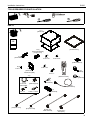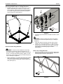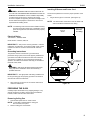
1
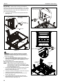
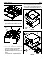
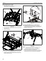
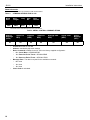
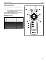
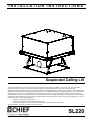
INSTALLATION INSTRUCTIONS
Instrucciones de instalación
Installationsanleitung
Instruções de Instalação
Istruzioni di installazione
Installatie-instructies
Instructions d´installation
Suspended Ceiling Lift
This device complies with part 15 of the FCC rules. Operation is subject to the following 2 conditions: (1) This device may not cause harmful
interference, and (2) this device must accept any interference received, including interference that may cause undesired operation.
This equipment has been tested and found to comply with the limits of a Class B digital device, pursuant to Part 15 of the FCC rules. These limits are
designed to provide reasonable protection against harmful interference in a residential installation. This equipment generates, uses and can radiate
radio frequency energy, and if not installed and used in accordance with the instructions, may cause harmful interference to radio or television
communications. However, there is no guarantee that the interference will not occur in a particular installation. If this equipment does cause harmful
interference to radio or television reception, which can be determined by turning the equipment off and on, the user is encouraged to try to correct
the interference by one of the following measures:
•
Reorient or relocate the receiving antenna
•
Increase the separation between the equipment and receiver
•
Connect the equipment to an outlet on a circuit other than that to which the receiver is connected
Consult the dealer or an experienced radio/TV technician for help
SL220
SL220
Installation Instructions
DISCLAIMER
Milestone AV Technologies, and its affiliated corporations and
subsidiaries (collectively, "Milestone"), intend to make this
manual accurate and complete. However, Milestone makes no
claim that the information contained herein covers all details,
conditions or variations, nor does it provide for every possible
contingency in connection with the installation or use of this
product. The information contained in this document is subject
to change without notice or obligation of any kind. Milestone
makes no representation of warranty, expressed or implied,
regarding the information contained herein. Milestone assumes
no responsibility for accuracy, completeness or sufficiency of
the information contained in this document.
Chief® is a registered trademark of Milestone AV Technologies.
All rights reserved.
IMPORTANT SAFETY INSTRUCTIONS
WARNING alerts you to the possibility of
serious injury or death if you do not follow the instructions.
CAUTION
alerts you to the possibility of
damage or destruction of equipment if you do not follow the
corresponding instructions.
WARNING
: FAILURE TO READ AND
FOLLOW THE FOLLOWING INSTRUCTIONS CAN RESULT
IN SERIOUS PERSONAL INJURY, DAMAGE TO EQUIPMENT
OR VOIDING OF FACTORY WARRANTY. Read these
instructions. Heed these instructions. Follow all instructions. It is
the installer’s responsibility to make sure all components are
properly assembled and installed using the instructions
provided.
When using an electrical mounting system, basic precautions
should always be followed, including the following:
READ ALL INSTRUCTIONS BEFORE USING THIS
PRODUCT!!!!
DANGER: TO REDUCE THE RISK OF
ELECTRIC SHOCK:
1. Always turn off power at source before cleaning.
2. Clean only with dry cloth.
CAUTION: Changes or modifications to this
unit not expressly approved by the manufacturer can void the
units FCC compliance rating and make the unit illegal to
operate.
WARNING: TO REDUCE THE RISK OF
BURNS, FIRE, ELECTRIC SHOCK, OR INJURY TO
PERSONS:
•
•
•
•
•
•
•
•
•
Always turn off power at source before putting on or
taking off parts.
Use this mounting system only for its intended use as
described in these instructions. Do NOT use
attachments not recommended by the manufacturer.
Never operate this mounting system if it has a
damaged cord or plug. If it is not working properly
during testing, return the mounting system to a service
center for examination and repair.
Keep the power cord away from heated surfaces.
Never operate the mounting system with the air
openings blocked. Keep the air openings free of lint,
hair, and the like.
Never drop or insert any object into any opening.
Do not use outdoors unless marked for outdoor use. Do
not use this apparatus near water.
Route cords and cables as shown in the installation
instructions.
To disconnect, turn all controls to the off position, then
turn off power at source.
WARNING:
RISK OF ELECTRIC SHOCK!
Connect this mounting system to a properly grounded outlet
only. See Grounding Instructions. Do not defeat the safety
purpose of the polarized or grounding-type plug. A polarized
plug has two blades with one wider than the other. A grounding
plug has two blades and a third grounding prong. The wide
blade or the third prong are provided for your safety. If the
provided plug does not fit into your outlet, consult an electrician
for replacement of the obsolete outlet.
WARNING:
Failure to provide adequate
structural strength for this component can result in serious
personal injury or damage to equipment! It is the installer’s
responsibility to make sure the structure to which this
component is attached can support five times the combined
weight of all equipment. Reinforce the structure as required
before installing the component.
WARNING
: Exceeding the weight capacity
can result in serious personal injury or damage to equipment! It
is the installer’s responsibility to make sure the weight of all
components attached to the SL220 does not exceed 30 lbs
(13.6 kg).
WARNING
: RISK OF INJURY! Do not place
video equipment such as televisions or computer monitors on
the ceiling pan of the SL220.
NOTE: This system has no user serviceable parts.
--SAVE THESE INSTRUCTIONS---KEEP THESE INSTRUCTIONS-2
Installation Instructions
TABLE OF CONTENTS
DISCLAIMER...................................................... 2
TABLE OF CONTENTS....................................... 3
TOOLS REQUIRED FOR INSTALLATION......... 4
PARTS................................................................ 4
LEGEND............................................................. 5
DIMENSIONS..................................................... 5
PREPARING FOR INSTALLATION.................... 6
Installation Requirements................................... 6
Power Requirements.......................................... 6
Preparing SL220 Framework.............................. 6
Installing SL220 Framework............................... 6
Securing SL220 Frame to Ceiling Structure....... 7
Solid Concrete Ceiling Structure................... 7
Steel Truss Ceiling Structure........................ 7
Wood Ceiling Structure................................. 8
Installing Cable to SL220 Frame......................... 8
Installing Junction Box and Outlet....................... 8
SL220
Grounding Instructions........................................ 9
PREPARING THE SL220................................... 9
Removing Ceiling Pan........................................ 9
Installing IR Sensor and Power Cord.................. 9
Removing Projector Cradle (Optional).............. 10
PLACING SL220 INTO CEILING STRUCTURE. 11
Replacing Projector Cradle............................... 12
Installing RPA/RPM, Bracket and Projector...... 12
Adjustments...................................................... 13
Connecting Control Wiring................................ 13
Replacing Ceiling Pan....................................... 14
OPERATING MODES....................................... 14
Projector Shutdown Mode (Optional)................ 14
Current Sense Mode (Optional)........................ 14
Fault Condition.................................................. 15
RS485 Information............................................ 16
Remote Control Capabilities...............................17
Table 4: Wiring Table.........................................18
Electrical Rating.................................................. 9
3
Installation Instructions
SL220
TOOLS REQUIRED FOR INSTALLATION
PARTS
A (1)
[SL220 Lift]
I/M
B (1)
[SL220 Frame]
D (4)
[Horizontal Bracket]
[2 right, 2 left]
x1
C (4)
[Vertical Bracket]
E (4)
6-32 x 1/2"
F (4)
6-32 x 5/16"
N (5)
[Cable tie mount]
G (2)
8-32 x 1/4"
H (1)
[Outlet box
attachment plate]
K (4)
10-24 x 1/2"
M (1)
[Remote control]
J (1)
J1 (4)
1/16" x 25’
[Wire Cable]
J3 (4)
1/4" x 2"
U (1)
[Projector cord]
J2 (4)
[Cable Support]
P (5)
[Cable tie]
L (5)
8-32 x 1"
T (3)
[Rubber grommet]
Q (1)
[Screwdriver]
S (1)
[IR receiver]
J4 (4)
0.262" x 1-5/16"
V (1)
[Projector cord]
R (1)
[Terminal block]
W (1)
[Power cord North America]
X (1)
[Power cord European]
4
Installation Instructions
SL220
LEGEND
Tighten Fastener
Phillips Screwdriver
Apretar elemento de fijación
Destornillador Phillips
Befestigungsteil festziehen
Kreuzschlitzschraubendreher
Apertar fixador
Chave de fendas Phillips
Serrare il fissaggio
Cacciavite a stella
Bevestiging vastdraaien
Kruiskopschroevendraaier
Serrez les fixations
Tournevis à pointe cruciforme
Loosen Fastener
Adjust
Aflojar elemento de fijación
Ajustar
Befestigungsteil lösen
Einstellen
Desapertar fixador
Ajustar
Allentare il fissaggio
Regolare
Bevestiging losdraaien
Afstellen
Desserrez les fixations
Ajuster
DIMENSIONS
4.19
1.99
ABSOLUTE MAXIMUM EQUIPMENT SIZE*
Height: 9.50"
Width: 16.50"
Length: 18.50"
Weight: 30#
3.19
13.75
FRONT
*The SL-220 requires either a RPM or RPA mount.
The height and weight of the mount needs to be
considered when calculating overall height and
total weight of the equipment used in the lift.
Total Forward/Aft adjustment of mount inside the lift:
5.00" [2 1/8" forward of center] [2 7/8" rear of center]
Total Lateral adjustment of mount inside the lift:
6.00" [3.00" either side of center]
1.99
23.31
22.13
FRONT
22.13
10.87 MIN
11.52 MAX
1.90
23.31
24.03 MAX
23.28 MIN
19.27
8.50
20.71
DIMENSIONS: [MILLIMETERS]
INCHES
5
SL220
Installation Instructions
PREPARING FOR INSTALLATION
Installation Requirements
The SL220 has been designed to be mounted recessed into a
suspended ceiling consisting of 2’ x 2’ ceiling tiles and secured
by a WireVice system.
Ceiling
Framework
Electrical Rating
100-250VAC~, 50/60Hz, 960W
North America: 120VAC, 60Hz, 8A
IMPORTANT ! : Installation and maintenance of this product
must be completed by a qualified service technician.
Preparing SL220 Framework
NOTE: Addition of the vertical bracket (C) is optional. The
2
vertical bracket is used to allow vertical adjustment into
the ceiling if a ceiling tile is attached to the bottom of the
SL220.
1.
2.
OPTIONAL: Attach vertical brackets (C) to both sides (in
each corner) of the SL220 frame (B) using a 06-32 x 5/16"
Phillips flat head screw (F). (See Figure 1)
Attach horizontal bracket (D) over the vertical bracket (C) at
each corner of the SL220 frame using a 06-32 x 1/2" Phillips
flat head screw (E). (See Figure 1)
(B)
Figure 2
(B)
3
Ceiling
Framework
(C)
(D)
(D)
Figure 1
Installing SL220 Framework
1.
2.
3.
4.
6
Remove one 2 ft x 2 ft tile from ceiling.
Insert SL220 frame (B) with attached brackets into the
empty ceiling space. (See Figure 2)
Set SL220 frame over top of ceiling framework, hooking
each horizontal bracket (D) onto the ceiling framework.
(See Figure 3)
Secure SL220 frame (B) to ceiling framework using one
10-24 x 1/2" Phillips head screw (K) through each horizontal
bracket (D) at each corner. (See Figure 3)
4
(K) x 4
Figure 3
(B)
Installation Instructions
SL220
Securing SL220 Frame to Ceiling Structure
1.
Examine ceiling structure (concrete, steel truss, or wood)
above SL220 frame (B) to identify four support cable
anchor locations. Each location should be approximately
15° outside of support holes in SL220 frame (B). Mark
locations with pencil. (See Figure 4).
1
(J3)
x4
x4
1
3
15°
x4
2
1/4"
15°
x4
4
(J1) x 4
Figure 5
2.
(B)
Tap anchor (J3) into each hole to a depth of at least 1". (See
Figure 5)
WARNING: Failure to properly set anchor may result in
failure of anchor and serious personal injury or damage to
equipment!
3.
Figure 4
4.
Solid Concrete Ceiling Structure
WARNING: Anchors must be installed into structurally
sound solid concrete with a minimum thickness of 1.75"
(44.5mm) or greater. Installation into hollow concrete block,
mortar, or concrete that exhibits cracking, spalling, or other
defects may result in failure of anchor and serious personal
injury or damage to equipment!
1.
Using claw portion of hammer, set each anchor (J3) by
pulling it out of hole approximately 1/4". (See Figure 5)
Insert portion of manufactured loop on cable (J1) through
hole in anchor (J3), and insert end of cable (J1) through
loop. Repeat for 3 remaining support locations.
(See Figure 5)
Steel Truss Ceiling Structure
1.
Route end of cable (J1) over truss at marked cable anchor
support location and then through cable loop. Repeat for 3
remaining support locations. (See Figure 6)
Drill 1/4" diameter x 1-1/8" deep pilot hole at each marked
cable anchor support location. Ensure hole is at least
2-1/2" from nearest concrete edge. Remove debris from
hole. (See Figure 5)
1
(J1) x 4
Figure 6
7
SL220
Installation Instructions
Wood Ceiling Structure
Installing Cable to SL220 Frame
WARNING: Anchors must be installed into wood with a
minimum thickness of 1-1/2" (38.1 mm) or greater.
1.
Drill a 5/32" diameter x 1-1/2" deep pilot hole at each
marked cable anchor support location. Ensure hole is at
least 5/8" from nearest wood edge. Remove debris from
hole. (See Figure 7)
CAUTION: Failure to properly tension cables (J1) may
result in damage to ceiling tile framework.
Thread each cable (J1) completely through cable lock (J2),
corresponding hole in corner of SL220 frame (B), and
completely through opposite side of cable lock (J2) (See
Figure 8).
2. Adjust cable tension until SL220 frame (B) is supported
entirely and evenly by all four support cables, but not so
tight as to distort ceiling tile framework.
1.
CAUTION: Cable lock (J2) will allow cable to enter from
only one direction per side, indicated by arrows on lock.
Depress spring loaded pins on cable lock (J2) to release
cable tension.
Installing Junction Box and Outlet
1.
Install Listed electrical box (not included) to outlet box
attachment plate (H).
Install the plate (H) with attached electrical box onto the
SL220 frame (B) using two 8-32 x 1/4" Phillips screws (G).
(See Figure 9)
2.
1
IMPORTANT ! : The junction box must be installed onto the
5/32"
2
(J4) x 4
3
(J1)
back of the frame (i.e. the side of the frame against the back of
the SL220).
Figure 7
2.
3.
Fully thread eye lag (J4) into each hole. (See Figure 7)
Route end of cable (J1) through eye lag (J4) and then
through cable loop. Repeat for 3 remaining support
locations. (See Figure 7)
1
2
(G) x 2
(H)
(B)
(J1)
(J2)
1
Back of SL220
will rest against
this side of frame.
Figure 8
8
Figure 9
Installation Instructions
SL220
Installing IR Sensor and Power Cord
WARNING: IMPROPER INSTALLATION CAN LEAD TO
LIFT FALLING CAUSING SEVERE PERSONAL INJURY OR
DAMAGE TO EQUIPMENT! It is the installers responsibility
to make certain the structure to which the lift is being
mounted is capable of supporting five times the weight of the
lift and all attached equipment. Reinforce the structure as
required before installing the lift.
The IR sensor placement is crucial to proper operation of the
SL220.
1.
Plug IR sensor (S) into control box. (See Figure 10)
NOTE: The final location of the sensor won’t be made until
after the SL220 is installed into the ceiling.
NOTE: The following instructions assume a suitable mounting
structure and surface exists prior to installation and all
power and signal wires and cables have been properly
installed.
(Some parts
removed
for clarity)
Front of
SL220
Electrical Rating
100-250VAC~, 50/60Hz, 960W
North America: 120VAC, 60Hz, 8A
IMPORTANT ! : This product must be grounded. If it should
malfunction or break down, grounding provides a path of least
resistance for electric current to reduce the risk of electric
shock.
Grounding Instructions
This product must be connected to a grounded metal,
permanent wiring system, and must be properly installed and
grounded in accordance with all local codes and ordinances.
This product is suitable for use in Other Environmental Air
Spaces in Accordance with Section 300.22(C) of the National
Electrical Codes, 2008.
1
Plug in IR
Receiver
WARNING: RISK OF ELECTROCUTION! All electrical
wiring required for installation should be installed by a
qualified electrician.
IMPORTANT ! : The appropriate outlet being installed must
be the grounding type and properly grounded in accordance
with all local codes and ordinances.
3.
Wire outlet into junction box in accordance with all local
codes and ordinances.
Figure 10
PREPARING THE SL220
Carefully inspect the SL220 for any shipping damage. If any
damage is apparent, do NOT continue with the installation.
Instead, contact Chief for further instructions.
Removing Ceiling Pan
1.
Place SL220 upside down on clean surface.
NOTE: The SL220 is shipped with the ceiling pan
disconnected, but in place.
2.
Remove ceiling pan and set aside.
9
SL220
Installation Instructions
IMPORTANT ! : Select power cord (W or X) suitable for
location. If neither of those cords are suitable for your location,
use a power cord that has an attachment plug on one end that
meets IEC-60320 and on the other end is appropriate for use
with the grounded main outlet.
2.
Grounding strap
Plug power cord into IEC inlet on rear panel inside SL220.
(See Figure 11)
(Some parts removed
for clarity)
1
x1
Plug in
power cord
2
Figure 12
IEC inlet
Front of
SL220
2
Front of SL220
Figure 11
WARNING: PINCH HAZARD! FINGERS OR HANDS
BETWEEN MOVING PARTS CAN LEAD TO SEVERE
PERSONAL INJURY! Keep fingers and hands away from
mount when operating.
3. Open and fully extend SL220 using remote control
following instructions included with the remote control and
instructions in the Remote Control Capabilities section.
4. Remove power cord.
Removing Projector Cradle (Optional)
NOTE: Removing the projector cradle is optional, but
1.
2.
3.
4.
10
recommended for a single person installation. If NOT
removing projector cradle, proceed to Placing SL220
into Ceiling Structure section.
Remove and save Phillips head screw and disconnect the
grounding strap leading from inside front of SL220 to
projector cradle. (See Figure 12)
Loosen the screws in the linkage on each side of projector
cradle at rear of SL220. (See Figure 13)
Gently pull projector cradle away from sides at rear of
SL220. (See Figure 14)
The forward/aft adjustment screws may need to be
loosened for this. If so, loosen the screws, but do NOT
remove the screws. (See Figure 13)
Adjustment
screws
Adjustment
screws
Figure 13
x2
Installation Instructions
SL220
4.
5.
Secure the SL220 (A) to the SL220 frame (B) using four
8-32 x 1" Phillips head screws (L), two in the front and two
in the back of the SL220. (See Figure 17)
Secure the outlet box attachment plate (H) to the SL220
using one 8-32 x 1" Phillips head screw (L). (See Figure 17)
3
(B)
3
(H)
Electrical
Opening
2
Front of SL220
Figure 14
5.
While still pulling the projector cradle away from the sides of
the SL220, slide front channels towards back, off of
bearings and remove projector cradle from SL220. (See
Figure 15)
(A)
4
Front
Channels
Rear of
SL220
Figure 16
3
(A)
(L) x 1
5
Front Channel
Bearings
3
3
Front Channels
3
Rear of
SL220
(B)
Figure 15
Corner
2 Hook
PLACING SL220 INTO CEILING STRUCTURE
1.
2.
3.
Orient SL220 so that the rear of the SL220 (with the
electrical opening) lines up with the outlet box attachment
plate (H) on the SL220 frame. (See Figure 16)
Lift SL220 (A) into place through the SL220 frame (B). (See
Figure 16) Ensure that there are four audible clicks---each
corner hook "clicking" into place onto the frame. (See
Figure 17)
Lower onto SL220 frame, carefully lining up outlet box
attached to SL220 frame, with opening at rear of SL220.
(See Figure 17)
4
(L) x 4
Figure 17
11
SL220
Installation Instructions
Replacing Projector Cradle
1.
Slide front channels of projector cradle forward onto the
SL220 bearings. (See Figure 18)
Front of
SL220
4
x1
Figure 20
1 Front Channels
Installing RPA/RPM, Bracket and Projector
1.
Figure 18
2.
3.
Line up rear spacers with attachment holes on SL220 arms.
(See Figure 19)
Tighten rear spacers.
3
Install RPA/RPM (a Listed accessory - not included) to the
projector cradle following instructions included with the
RPA/RPM. (See Figure 21)
x2
Rear of
SL220
RPA
Figure 21
NOTE: The projector is secured from the top by an SLB
bracket (a Listed accessory - not included).
2.
Figure 19
4.
12
Reconnect grounding strap from inside front of SL220 to
projector cradle, using the Phillips head screw previously
removed. (See Figure 20)
3.
Attach the SLB bracket to the projector following the
instructions included with the SLB bracket.
Attach the SLB bracket with the projector to the RPA/RPM
following the instructions included with the RPA/RPM.
Installation Instructions
SL220
1.
Adjustments
1.
2.
3.
Adjust projector left or right by loosening the wing nuts on
the SL220 cross bracket. (See Figure 22)
Slide the SL220 cross bracket to the left or right as required.
Tighten wing nuts. (See Figure 22)
Use two-sided tape, or a similar attachment device to attach
the IR sensor (S) in a convenient location for your
installation.
NOTE: Ensure that IR sensor "eye" has "line of sight" to the
remote control signal.
2.
3.
Insert terminal block (R) into SL220. (See Figure 24)
Connect control wiring following instructions included with
the third party automation and control equipment and usersupplied switching devices, and information in Wiring Table
(See Table 4).
NOTE: Any knockouts removed in the SL220 must be
replaced with a supplied rubber grommet (T).
Projector
SLB Bracket
4.
2
Feed the video and/or communications cables through the
knockouts in the rear or top of the lift and connect it to the
projector.
SL220 Cross
Bracket
1
(Top View shown)
Dip switches
(labeled 1
8)
3
Figure 22
4.
5.
6.
Adjust projector forward or backward by loosening two
screws on each side of SL220. (See Figure 23)
Slide projector forward or backward as required.
Tighten two screws on each side of SL220. (See Figure 23)
2 Insert terminal
block here
5
Figure 24
5.
4
6
Figure 23
7.
Any pitch, roll or yaw adjustments should be made following
instructions included with the RPA/RPM.
OPTIONAL: Use appropriate projector cord (U or V) to
connect projector to IEC outlet on rear panel inside SL220.
(See Projector Shutdown Mode (Optional) section.)
IMPORTANT ! : Select projector cord (U or V) suitable for
projector. If neither supplied cord is appropriate for projector,
use a projector cord that has an attachment plug on one end
that meets IEC-60320 and on the other end is appropriate for
use with the projector being used with the lift.
Connecting Control Wiring
CAUTION: SHOCK, INJURY OR DAMAGE TO
EQUIPMENT IS POSSIBLE! Avoid placing cables near
moving parts and pinch points to avoid damage to the cables.
Ensure there is enough slack in the cables to allow for up and
down movement of the lift.
WARNING: All wiring should be
performed following all local codes and
ordinances.
6.
Secure cables as necessary using supplied mounting pads
(N) and cable ties (P).
13
SL220
Installation Instructions
CAUTION: KEEP SL220 OPEN WHILE PROJECTOR IS
RUNNING OR IN COOLING MODE! Premature bulb failure
or damage to electrical components may occur if lift closes.
Replacing Ceiling Pan
1.
2.
3.
4.
Line up small peg on ceiling pan with hole in leg of projector
cradle. (See Figure 25)
Attach spring on projector cradle to hook on ceiling pan.
(See Figure 25)
Repeat for all four corners of the ceiling pan.
Replace power cord.
Ceiling Pan
Spring
Shutdown feature
enabled when
this side of
switch pressed
Shutdown feature
disabled when
this side of
switch pressed
Ceiling
Pan Leg
IEC outlet
Shutdown mode
rocker switch
Figure 25
Figure 26
OPERATING MODES
Projector Shutdown Mode (Optional)
IMPORTANT ! : The SL220 has a shutdown feature which
removes power from the projector when the lift is retracted. This
prevents possible damage to the projector if the SL220 is
inadvertently closed while the projector is on.
By default, this feature is disabled. To enable or disable this
feature, use the rocker switch directly above the IEC outlet. To
enable depress the blank side of rocker switch. To disable
depress the white dot side of rocker switch. The projector
MUST be plugged into the IEC outlet in order for this feature to
function. (See Figure 26)
IMPORTANT ! : Select projector cord (U or V) suitable for
projector. If neither supplied cord is suitable for projector, use a
projector cord that has an attachment plug on one end that
meets IEC-60320 and on the other end is appropriate for use
with the projector being used with the lift.
NOTE: Projector MUST be plugged into the IEC outlet located
within the lift. (See Figure 26)
NOTE: Enabling this feature may have an adverse effect on
projector bulb life.
Current Sense Mode (Optional)
IMPORTANT ! : The SL220 MUST be extended when this
process is started.
NOTE: Projector MUST be plugged into the IEC outlet located
within the lift. (See Figure 26)
IMPORTANT ! : Select projector cord (U or V) suitable for
projector. If neither supplied cord is suitable for projector, use a
projector cord that has an attachment plug on one end that
meets IEC-60320 and on the other end is appropriate for use
with the projector being used with the lift.
14
1.
2.
Extend lift.
Make sure Projector Shutdown Mode is disabled. (See
Figure 26)
3. Flip DIP switch #8 (See Figure 24) to activate the Current
Sense mode.
4. Turn on the projector so that the lift will learn the normal
current draw of the projector.
NOTE: Allow projector to fully warm up.
5.
Turn off projector.
In most cases, the lift will be able to detect the fan on the
projector shutting off. However, the lift cannot detect this on all
projector models.
If a fan shutoff was not detected by the lift within 5 minutes
(default setting) of the projector turning off, the lift will
automatically close assuming that the fan turning off was
undetected.
The amount of time the lift waits between when it senses the
projector turn off and when the lift assumes the fan turn-off was
missed is adjustable. (See Table 1)
Table 1: EQUIPMENT COOLDOWN
Equipment Cooldown
Time
Dipswitches 5 & 6
5 Minutes
5 Off; 6 Off (Default)
3 Minutes
5 On; 6 On
2 Minutes
5 Off; 6 On
1 Minute
5 On; 6 Off
Installation Instructions
SL220
Fault Condition
IMPORTANT ! : If the SL220 control system sees a fault
condition it will stop the operation and a red light will flash on
the control board (visible through the control housing).
For most faults:
1.
Correct the problem. (Oftentimes, the cord routing may
need to be corrected.)
2. Press STOP on the supplied remote control (M) which will
reset the system and allow normal function.
NOTE: If there are repeated faults, please contact Chief
Technical Support.
15
SL220
Installation Instructions
RS485 Information
Communication parameters as specified in ANSI TIA/EIA-485-A:
Table 2:
COMMAND STRINGS FOR SL-220
Baud
Rate
Data
Length
Parity
8 Bits
None
9600
•
Stop
Bit
Flow
Control
1
None
The serial control command string is set up as follows:
Table 3: SERIAL CONTROL COMMAND STRING
Start of
Message
(HEX)
Product ID
(HEX)
3E
•
•
•
•
•
16
XX
Address
(HEX)
XX
Command
(HEX)
XX
Message Data
(HEX)
Check Code
(HEX)
XX
Product ID for the SL-220: 05
Address controlled by dip switch settings
Basic Commands available for the SL-220 in the factory-supplied configuration:
• 03: Cancel Move = 3E0500037D0D
•
10: Extend to End of Travel = 3E0500107B0D
•
12: Retract to End of Travel = 3E0500127D0D
Message Data = The data is required for the available commands:
• 03: None
•
10: None
•
12: None
Check Code is calculated.
XX
End of
Message
(HEX)
0D
Installation Instructions
SL220
Remote Control Capabilities
The remote control has a range of 20-30ft (6-9m), and is
powered by 2 AAA batteries that are accessed from the back of
the remote.
5
1
9
NOTE: If operation of the mount is required at a greater
distance than remote control will allow, the mount can
be controlled through other methods.
The following table and illustration identify mount functionality
and response by button on the remote control.
3
4
Normal Operating Mode
KEY
FUNCTION
REQUIRED ACTION
1
MOVE DISPLAY TO HOME
2
EXTEND PROJECTOR
N/A
3
NOT USED
N/A
4
NOT USED
N/A
5
RETRACT PROJECTOR
6
PRESET POSITION 1
NOT USED
7
PRESET POSITION 2
NOT USED
8
PRESET POSITION 3
NOT USED
9
SAVE PRESET POSITION
10
STOP
PRESS ONCE
2
10
PRESS ONCE
NOT USED
6
7
8
PRESS ONCE
Figure 27
17
SL220
Installation Instructions
Table 4: WIRING TABLE
18
Installation Instructions
SL220
19
SL220
Installation Instructions
USA/International
Chief Manufacturing, a products division
of Milestone AV Technologies
Europe
Asia Pacific
8820-002009 Rev02
2011 Milestone AV Technologies, a
Duchossois Group Company
www.chiefmfg.com
01/11
A
P
F
A
P
F
A
8401 Eagle Creek Parkway, Savage, MN 55378
800.582.6480 / 952.894.6280
877.894.6918 / 952.894.6918
Fellenoord 130 5611 ZB EINDHOVEN, The Netherlands
+31 (0)40 2668620
+31 (0)40 2668615
Office No. 1 on 12/F, Shatin Galleria
18-24 Shan Mei Street
Fotan, Shatin, Hong Kong
P 852 2145 4099
F 852 2145 4477