1
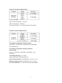
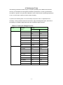
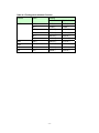
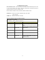
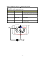
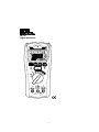
#61-797
Digital Multimeter
-1-
TABLE OF CONTENTS
1.Introduction
Precautions and Safety Information
Symbols
Safety
2.Specifications
General Specifications
Electrical Specifications
Required Equipment
3.Basic Maintenance
Battery and Fuse Replacement
4. Performance Tests
5. Calibration Procedure
-2-
1. Introduction
Warning
To avoid shock or injury, do not perform the verification tests or calibration
procedures described in the manual unless you are qualified to do so.
The information provided in this document is for the use of qualified personnel only.
Caution
The meter contain parts that can be damaged by static discharge.
Follow the standard practices for handling static sensitive devices.
For additional information about APPA TECHNOLOGY CORP.
and its products, and services, visit APPA TECHNOLOGY
CORP. web site at:
www.appatech.com
Precautions and Safety Information
Use the Meter only as described in the Service Manual. If you do not do
so, the protection provided by the Meter may be impaired. Read the
“Safety Information” page before servicing this product.
In this manual, a Warning identifies conditions and actions that pose
hazard (s) to the user; a Caution identifies conditions and actions that
may damage the Meter or the test instruments.
The Symbols
The symbols used on the Meter and in this manual are explained in
Table 1.
Table 1-1. The Symbols
-3-
SAFETY
Review the following safety precautions to avoid injury and prevent damage to this
product or products connected to it. To avoid potential hazards, use the product
only as specified.
CAUTION: These statements identify conditions or practices that could result
in damage to the equipment or other property.
WARNING: These statements identify conditions or practices that could result
in personal injury or loss of life.
Specific precautions
Do not operate without covers. To avoid personal injury, do not apply any voltage
or current to the product without covers in place.
Electric overload. Never apply a voltage to a connector on the product that is
outside the range specified for that connector.
Avoid electric shock. To avoid injury or loss of life, do not connect or disconnect
probes or test leads while they are connected to a voltage source.
Do not operate in wet/damp conditions. To avoid electric shock, do not operate
this product in wet or damp conditions.
-4-
2. Specifications
General Specifications
Maximum voltage applied to any terminal :
600 V ac rms or dc.
Display : 4000 counts.
Polarity Indication :
Automatic, positive implied, negative indicated.
Overrange Indication : OL
Batteries Life :
Resistance Measurements : Tester can perform at least 2600
earth-bond resistance measurements with new alkaline batteries
at room temperature. These are standard tests of 1Ω with
a duty cycle of 5 seconds on and 25 seconds off.
Insulation test: Tester can perform at least 1100 insulation tests
with new alkaline batteries at room temperature.
These are standard tests of 1 MΩ at 1000 V with a duty cycle
of 5 seconds on and 25 seconds off.
Low Batteries Indication : "
" is displayed when the batteries
voltage drops below operating voltage.
Low battery voltage : Approx. 4.5V
Auto Power Off : Approx 20 minutes.
Operating Ambient : Non-condensing ≦10°C,
11°C ~ 30°C (≦80% RH),
30°C ~ 40°C (≦75% RH),
40°C ~ 50°C (≦45%RH)
Storage Temperature :
-20°C to 60°C , 0 to 80% R.H. (batteries not fitted)
Temperature Coefficient :
0.15 x (Spec.Accy)/°C, < 18°C or > 28°C .
Measure : Samples 2 times per second nominal.
Altitude : 6561.7 ft (2000m)
Safety : Complies with EN61010-1, UL61010-1,IEC 61010-1,
V/Ω : CAT.IV. 600V.
Compliance to EN 61557 : IEC61557-1, IEC61557-2,
IEC61557-4, IEC61557-10
Weight : (630g) including battery.
Dimensions (W x H x D) :
95mm x207mm x 52mm with holster.
-5-
Accessories : Battery (installed), Test leads and user manual.
Power Requirements : 1.5V x 4 IEC LR6 or AA size.
Pollution degree : 2
EMC : EN 61326-1
Shock vibration : Sinusoidal vibration per MIL-T- 28800E
(5 ~ 55 Hz, 3g maximum).
Drop Protection :
4 feet drop to hardwood on concrete floor.
Indoor Use.
-6-
Electrical Specifications
Accuracy is ±(% reading + number of digits) at 23°C ± 5°C
< 80%RH.
Voltage Measurement
Start measuring voltage : ≧ AC 0.6V.
Over voltage protection : 600V rms or ac.
Input Impedance : 3MΩ // less than 100pF.
CMRR / NMRR : (Common Mode Rejection Ratio)
(Normal Mode Rejection Ratio)
VAC : CMRR > 60dB at DC, 50Hz / 60Hz
VDC : CMRR > 100dB at DC, 50Hz / 60Hz
NMRR > 50dB at DC, 50Hz / 60Hz
AC Conversion Type :
AC Conversions are ac-coupled, true rms responding, calibrated to the rms value of a
sine wave input.
For non-sine wave add the following Crest Factor corrections:
For Crest Factor of 1.4 to 2.0, add 1.0% to accuracy.
For Crest Factor of 2.0 to 2.5, add 2.5% to accuracy.
For Crest Factor of 2.5 to 3.0, add 4.0% to accuracy.
CF 3 @ 330V
2 @ 500V
-7-
Earth-bond resistance Measurement
*<1.00Ω add 3dgt
Open Circuit Test Voltage : >4.0V,<8V
Short Circuit Current : >200.0mA
Live Circuit Detection: if≧2V ac/dc at inputs, test inhibited.
Insulation resistance Measurement
Test Voltage vs. Maximum resistance range :
50V/50.0MΩ,100V/100.0MΩ,250V/250.0MΩ,500V/500MΩ
and 1000V/20.0GΩ.
Test Voltage vs. Minimum resistance (with test
current=1mA) :
50V/50kΩ,100V/100kΩ,250V/250kΩ,500V/500kΩ and
1000V/1MΩ.
Test Voltage Accuracy : -0%,+20%
Short Circuit Test Current:1mA(nominal)
Auto discharge function : discharge time<1 sec for C≦1µF
Maximum Capacitive load : Operable with up to 1µF load
Live Circuit Detection : if≧30V ac/dc at inputs, test inhibited
-8-
Required Equipment
Required equipment is listed in Table B. If the recommended models
are not available, equipment with equivalent specifications may be
used.
Repairs or servicing should be performed only by qualified personnel.
Table 2-1
Equipment
Required Characteristics
Recommended Model
Calibrator
AC Voltage Range: 0 - 600 V
Fluke 5700 or Wavetek
Frequency Range: 50 Hz - 500 Hz 9100 Calibrator
Accuracy: +/- 0.1%(Basic)
DC Voltage: 0 - 600 V
Accuracy: +/-0.1%(Basic)
DC Current: 0-400mA
Accuracy: +/-0.1%(Basic)
DMM
DC Voltage: 0 - 1000 V
Accuracy: +/-0.5%(Basic)
DC Current: 0-400mA
Accuracy: +/-0.5%(Basic)
High voltage
Divider
DC Voltage Range: 1 kV -5 kV
Fluke 80k-6
Accuracy: 1%
Division Ratio: 1000:1
Input resistance: 1000 MΩ
High voltage Suggest the insulation tester
to use physical high voltage
Resistor
resistors at ± 5% tolerance
(>1kV)
as listed:50kΩ, 100kΩ,
To verify the actual
resistance value by Fluke
8508. Then, use the actual
value to calibrate the
250kΩ, 500kΩ, 1MΩ, 40M insulation meter.
Ω, 400MΩ, 4GΩ, 18GΩ
Resistor
Suggest the insulation tester Same as above
to use physical high voltage
resistors at ± 1% tolerance
as listed:2Ω(0.5W),36
Ω,360Ω,3.6kΩ,36kΩ
-9-
3. Basic Maintenance
To avoid shock, remove the test leads and any input signals before opening the case or
replacing the battery.
Battery and Fuse Replacement
Refer to the following figure to replace fuse and the batteries:
- 10 -
4. Performance Tests
The following performance tests verify the complete operability of the Meter and check the
accuracy of each Meter function against the Meter’s specifications. Accuracy specifications
are valid for a period of one year after calibration, when measured at an operating temperature
of 18°C to 28°C and a maximum of 80% relative humidity.
To perform the following tests, it is not necessary to open the case, no Adjustments are
necessary, merely make the required connections, apply the designated inputs, determine if
the reading on the Meter display falls within the acceptable range indicated.
Table 4-1 Testing the Voltage Function
function
DCV
ACV
Calibrator
Reading
Output
Low limit
High limit
2
1.5V
2.5V
-2
-2.5V
-1.5V
60
-58.9V
61.1V
-60
-61.1V
-58.9V
300
296.5V
303.5V
-300
-303.5V
-296.5V
600
593.5V
606.5V
-600
-606.5V
-593.5V
2V ,50Hz
1.5V
2.5V
54V ,50Hz
52.7V
55.3V
66V ,50Hz
64.5V
67.5V
300V,50Hz
295.0V
305.0V
600V,50Hz
590.5V
609.5V
2V ,500Hz
1.5V
2.5V
54V ,500Hz
52.4V
55.6V
66V ,500Hz
64.2V
67.8V
300V,500Hz
293.5V
306.5V
600V,500Hz
587.5V
612.5V
- 11 -
function
LPF ACV
Table 4-2
function
Ω
Calibrator
Reading
Output
Low limit
High limit
2V ,50Hz
1.5V
2.5V
54V ,50Hz
52.7V
55.3V
66V ,50Hz
64.5V
67.5V
300V,50Hz
295.0V
305.0V
600V,50Hz
590.5V
609.5V
2V ,400Hz
1.4V
2.6V
54V ,400Hz
50.8V
57.2V
66V ,400Hz
62.2V
69.8V
300V,400Hz
284.5V
315.5V
600V,400Hz
569.5V
630.5V
Testing the Earth-bond Function
Applied
Reading
Low limit
High limit
2.00Ω
1.92Ω
2.08Ω
36.00Ω
35.41Ω
36.59Ω
360.0Ω
354.3Ω
365.7Ω
3600Ω
3543Ω
3657Ω
36.00kΩ
35.43kΩ
36.57kΩ
- 12 -
Table 4-3 Testing the Insulation Function
function
Applied
Reading
Low limit
High limit
18GΩ
15.9GΩ
20.1GΩ
4GΩ
3875MΩ
4125MΩ
400MΩ
387.5 MΩ
412.5 MΩ
40MΩ
39.35 MΩ
40.65 MΩ
4MΩ
3.935 MΩ
4.065 MΩ
1MΩ
0.980 MΩ
1.020 MΩ
500V
500kΩ
0.488 MΩ
0.512 MΩ
250V
250kΩ
0.241MΩ
0.259 MΩ
100V
100kΩ
0.993 MΩ
0.107 MΩ
50V
50kΩ
0.045MΩ
0.055 MΩ
1000V
- 13 -
5. Calibration Procedure
Enter Calibration mode:Press and hold the TEST button, and simultaneously turn the UUT
on, wait until the display shows “8888”. Release the TEST button, and press the button as
following sequence to enter the calibration mode:
BLUE=>COMP=>STORE=>LOCK=>STORE=>COMP=>STORE=>LOCK
STORE button: Press once to save the calibration value, and “SAVE”
will be displayed.
COMP button : Press once to enter the next step.
Table 5-1 Calibration steps for insulation function
Switch position: 50V insulation
Input Terminal: +: COM / -: gnd(remote probe pin)
Adjustment Step
Standard value
Press button
01L
1.600mA, 0Hz
Waiting for reading stable, press STORE
button.
0102L
Check the reading, and press COMP button
540.0uA, 0Hz
Same as above.
160.0uA, 0Hz
Same as above.
54.00 uA, 0Hz
Same as above.
16.00uA, 0Hz
Waiting for reading stable, press STORE button
0203L
0304L
0405L
05-
Check the reading
- 14 -
Table 5-2 Calibration steps for Ω(Earth-bond) function
Switch position: Ω/->0<Input Terminal: +: COM / -:gnd(remote probe pin)
Adjustment Step
Standard value
Press button
06L
360.0mA, 0Hz
Waiting for reading stable, press STORE button
0607L
Check the reading, and press COMP button
36.00mA, 0Hz
Same as above.
3.600mA, 0Hz
Same as above.
360.0uA, 0Hz
Waiting for reading stable, press STORE button
0708L
0809L
09-
Check the reading
- 15 -
Table 5-3 Calibration steps for Ω(Earth-bond) function
Switch position: Ω/->0<Input Terminal: +:Ω input/ -:COM
Adjustment Step
Standard value
Press button
10L
0.560V, 0Hz
Waiting for reading stable, press STORE button
10H
3.600V, 0Hz
Same as above.
10-
Check the reading, and press COMP button
11L
1.800V, 50Hz
Waiting for reading stable, press STORE button
11-
Check the reading, and press COMP button
12L
0.00Ω(Short the inputs) Waiting for reading stable, press STORE button
12-
Check the reading.
Table 5-4 Calibration steps for Voltage function
Switch position :V
Input Terminal :+:V input/ -:COM
Adjustment Step
Standard value
Press button
13L
10.0V
Waiting for reading stable, press STORE button
13H
100.00V
Waiting for reading stable, press STORE button
13-
Check the reading, and press COMP button
14L
30.0V
14H
750.0V
Same as above
1415L
5.6V, 50Hz
15H
56.0V, 50Hz
Same as above
1516L
56.0V, 50Hz
16H
560.0V, 50Hz
Same as above
1617L
( LPF )
17H
5.6V, 50Hz
Same as above
56.0V, 50Hz
1718L
18H
18-
( LPF )
56.0V, 50Hz
Waiting for reading stable, press STORE button
560.0V,50Hz
Waiting for reading stable, press STORE button
Check the reading.
- 16 -
Table 5-5 Calibration steps for Battery voltage
Switch position :100V insulation
Input Terminal:+: Battery + Terminal / -: Battery – Terminal
Adjustment Step
Standard value *
Press button
19L
5.00V
Waiting for reading stable, press STORE button
19-
Check the reading.
* Remove batteries from UUT battery compartment. Connect a + 5.00 V lab supply
to the + and - battery terminals.
Table 5-6
Switch position :1000V insulation
output Terminal:+:V input/ -:COM(disconnect the test leads)
Adjustment Step
Standard value
Press button
20L
55V±3V
Press the TEST button to output and display
the test voltage.
Press the BLUE/COMP button to lower or
raise the test voltage.
Then press STORE button to save the
calibration value.
(The test voltage will be automatically
turned off when STORE button is pressed)
20-
Press TEST button to output and display the
Test voltage.
Check the reading, and press COMP button
21L
110V±3V
Same as above.
275V±5V
Same as above.
525V±5V
Same as above.
1050V±5V
Same as above.
2122L
2223L
2324L
24z
If
the measured value is greater than 130% of Standard value or lower than 70% of Standard
value,”Er” symbol will be displayed, and the STORE button is not available.
- 17 -