1
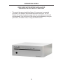
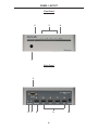
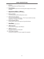
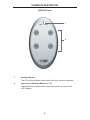
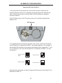
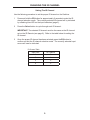
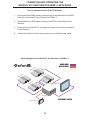
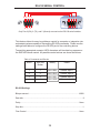
4X1 Gefen TV Switcher
GTV-HDMI1.3-441N
User Manual
www.gefentv.com
ASKING FOR ASSISTANCE
Technical Support:
Telephone
Fax
(818) 772-9100
(800) 545-6900
(818) 772-9120
Technical Support Hours:
8:00 AM to 5:00 PM Monday thru Friday Pacific Time
Write To:
Gefen, LLC
c/o Customer Service
20600 Nordhoff St
Chatsworth, CA 91311
www.gefentv.com
[email protected]
Notice
Gefen, LLC reserves the right to make changes in the hardware, packaging and
any accompanying documentation without prior written notice.
4x1 GefenTV Switcher is a trademark of Gefen, LLC
TM
logo and High-Definition Multimedia Interface are
HDMI , the
trademarks or registered trademarks of HDMI Licensing in the United States and
other countries.
© 2011 Gefen, LLC, All Rights Reserved
All trademarks are the property of their respective companies
Rev A3
CONTENTS
1
Introduction
2
Operation Notes
3
Features
4
Panel Layout
5
Panel Descriptions
6
IR Remote Description
7
IR Remote Installation
8
IR Remote Configuration
9
Changing the IR Channel
10
Connecting and Operating the GefenTV 4x1 Switcher for HDMI 1.3
10
Wiring Diagram
11
Controlling the GefenTV 4x1 Switcher for HDMI 1.3
11
Automatic Switching
12
RS-232 Serial Control
12
Settings
13
Commands
15
Specifications
16
Warranty
INTRODUCTION
Congratulations on your purchase of the 4x1 GefenTV Switcher. Your complete
satisfaction is very important to us.
GefenTV
GefenTV is a unique product line catering to the growing needs for innovative
home theater solutions. We specialize in total integration for your home theater,
while also focusing on going above and beyond customer expectations to ensure
you get the most from your hardware. We invite you to explore our distinct
product line and hope you find your solutions.. Don’t see what you are looking for
here? Please call us so we can better assist you with your particular needs.
The GefenTV Switcher
The GefenTV 4x1 Switcher for HDMI with RS232 switches between any of four
Hi-Def sources to one HDTV display. Resolutions up to 1080p Full HD with
multichannel digital audio are supported. 3D content can be displayed when
connecting a 3DTV and 3D source. The front panel LEDs show the currently
selected source. This 4x1 Switcher has an auto-switching feature: If a new
source is connected or turned on, the Switcher will automatically switch to that
input. The 4x1 Switcher will revert to the previous input once the current device is
turned off or disconnected. Any of the four Hi-Def sources can be selected by the
push-button, IR remote control, or using the RS-232 control.
How It Works
Connect up to four HDMI sources to the GefenTV 4x1 Switcher for HDMI with
RS232 using the supplied cables. Connect the HDTV display to the HDMI output.
Connect the 5V power supply to the 4x1 Switcher. Apply power to the source
devices and the display. The Hi-Def source is displayed and will follow the current
switching selection.
1
OPERATION NOTES
READ THESE NOTES BEFORE INSTALLING OR
OPERATING THE 4X1 GEFEN TV SWITCHER
•
This product has an auto-switching feature: If a new source is connected
or turned on, the Switcher will automatically switch to that input. The 4x1
Switcher will revert to the previous input once the current device is turned off
or disconnected. Any of the four Hi-Def sources can be selected by using the
push-button, IR remote control, or using the RS-232 control.
®
2
FEATURES
HDMI 1.3 Features
•
225 MHz (up to 12-bit YUV 444 @ 1080p)
•
Deep Color
•
Dolby TrueHD and DTS HD Master Audio
•
Lip-Sync
•
CEC Pass-Through
Features
•
Supports resolutions up to 1080p Full HD and 1920x1200
•
3DTV Pass-Through
•
Supports LPCM 7.1 audio, Dolby Digital Plus, Dolby TrueHD, and DTS-HD
Master Audio
•
Local Switching / Auto-Switching feature
•
RS-232 control
•
IR remote control
•
Supports DVI sources and DVI displays with an HDMI-to-DVI adapter
•
Energy Star Compliant
Package Includes
(1) GefenTV 4x1 Switcher for HDMI with RS232
(4) 6 ft. HDMI cable (M-M)
(1) 6 ft. DB9 Serial Cable (M-F)
(1) IR Remote Control unit
(1) 5V DC Power Supply
(1) User Manual
3
PANEL LAYOUT
Front Panel
2
3
4
®
1
Back Panel
5
6
7
8
9
4
10
PANEL DESCRIPTIONS
1
IR Sensor
Receives signals from the IR Remote Control.
2
Power Indicator
This LED will turn bright red once the locking power supply has been properly
connected.
3
Input Indicators (HDMI In 1 - HDMI In 4)
Displays the current input of the 4x1 Switcher.
4
Enhance Indicator
This LED indicates that EQ (Pre-Emphasis) is active.
5
RS-232 Serial Port (Output)
Connects to the RS-232 control device. The 4x1 may be switched remotely
using this port. See page 12 for details.
6
EQ (Pre-Emphasis) Button
Use this button to improve the signal over long cable distances.
7
Select Button
Used to select the input source.
8
HDMI Output Port
Connect an HDTV display to this HDMI port.
9
HDMI Input Ports (4)
Connect a Hi-Def source to these ports.
10 5V DC Power Connector
Connects the included 5V DC power supply to this receptacle.
5
IR REMOTE DESCRIPTION
RMT-4IR Remote
1
2
1
Activity Indicator
This LED will be activated momentarily each time a button is pressed.
2
Input Source Selection Buttons (1 - 4)
These buttons are used to select which input source is routed to the
HDTV display.
6
IR REMOTE INSTALLATION
Installing the IR Remote Control Battery
1.
Remove the battery cover on the back of the IR Remote Control unit.
2.
Insert the included battery into the open battery slot. The positive (+) side of
the battery should be facing up.
3.
Replace the battery cover.
The Remote Control unit ships with two batteries. One battery is required for
operation and the other battery is a spare.
Battery Slot
7
IR REMOTE CONFIGURATION
Resolving IR Code Conflicts
In the event that IR commands from other remote controls conflict with the
supplied IR remote control unit, changing the remote channel will alleviate this
issue. The IR remote control unit has a bank of DIP switches for setting the
remote IR channel.
The DIP Switch bank on the IR remote control unit is located underneath the
battery cover.
DIP Switches
It is important that the IR channel selected on the remote, match the IR channel
on the GefenTV 4x1 Switcher for HDMI 1.3 for proper operation. For example, if
you set both DIP switches on the remote to the down position (toward the “1” and
“2”), IR channel 0, you must set the GefenTV 4x1 Switcher for HDMI 1.3 to use
IR channel 0.
Remote Channel 0:
Default
Remote Channel 1:
1
2
Remote Channel 2:
1
2
1
2
Remote Channel 3:
1
2
See page 9 for information on how to change the IR channel on the GefenTV 4x1
Switcher for HDMI 1.3.
8
CHANGING THE IR CHANNEL
Setting The IR Channel
Use the following procedure to set the proper IR channel on the Switcher.
1
Press and hold the EQ button for approximately 5 seconds to enter the IR
channel selection mode. The currently selected IR channel will by indicated
by a flashing blue LED on the Input Indicators (page 5).
2
Press the Select button to cycle through each IR channel.
IMPORTANT: The selected IR channel must be the same as the IR channel
set on the IR Remote (see page 8). Refer to the table below for setting the
IR channel.
3
Once the proper IR channel has been selected, press the EQ button to
confirm and exit the IR channel selection mode. The currently selected input
source will now be indicated.
IR Channel Table
Input LED
IR Channel
1
0
2
1
3
2
4
3
9
CONNECTING AND OPERATING THE
GEFENTV 4X1 SWITCHER FOR HDMI1.3 WITH RS232
How to Connect the 4x1 GefenTV Switcher
1.
Use the provided HDMI cables to connect the source devices to the HDMI
input port of the GefenTV 4x1 Switcher for HDMI 1.3.
2.
Use an additional HDMI cable to connect an HDTV to the Output on the
Switcher.
3.
Connect the included 5V DC locking power supply to the power receptacle
on the Switcher.
4.
Connect the other end of the power supply to an available power outlet.
Wiring Diagram for the GefenTV 4x1 Switcher for HDMI 1.3
M
IS
ou
rc
e
H
D
H
M
D
IS
M
ou
IS
rc
ou
e
rc
e
H
D
M
IS
ou
rc
e
HDMI CABLE
RS-232 CABLE
H
D
HDMI Display
HDMI Switcher
GTV-HDMI1.3-441N
RS-232 Controller
10
CONTROLLING THE THE GEFENTV
4X1 SWITCHER FOR HDMI1.3 WITH RS232
How to control the GefenTV 4x1 Switcher for HDMI 1.3
There are three ways to control the GefenTV 4x1 Switcher for HDMI with RS232:
1. Use the IR Remote Control Unit to select the current source. Each
corresponding to a numbered source connected on the back of the Switcher. The
corresponding source will be shown on the display.
2. Press the Select button on the rear of the unit to cycle through each input
source.
3. Send RS-232 commands to the serial port on the rear panel via computer or a
control automation device. Page 12 for details.
Automatic Switching
The GefenTV 4x1 Switcher for HDMI 1.3 has an auto-switching feature: If a new
source is connected or turned on, the Switcher will automatically switch to that input.
The 4x1 Switcher will revert to the previous input once the current device is turned
off or disconnected. The remote and input select button will always allow you to
switch manually. The IR Remote Control Unit will switch discretely to any input,
while the Select button will allow you to toggle between inputs.
11
RS-232 SERIAL CONTROL
54321
12345
9876
6789
Only Pins 2 (RX), 3 (TX), and 5 (Ground) are used on the RS-232 serial interface
This feature allows for easy long-distance control by computer or integration into
automated systems capable of transmitting RS-232 commands. Please use the
settings listed below to configure the RS-232 port of the controlling device.
Transmitting appropriate numeric ASCII characters will simulate key presses on
the RMT-4IR remote control. All possible control actions are shown as follows:
Table of Commands and Results
ASCII
RMT-4IR
Button
Binary
Result
1
1
0011 0001
Selects Input 1
2
2
0011 0010
Selects Input 2
3
3
0011 0011
Selects Input 3
4
4
0011 0100
Selects Input 4
RS-232 Settings
Bits per second ................................................................................................. 19200
Data bits .................................................................................................................... 8
Parity .................................................................................................................. None
Stop bits .....................................................................................................................1
Flow Control ....................................................................................................... None
12
RS-232 SERIAL CONTROL
Commands
These commands are not case-sensitive.
Command
Description
A
Enable Auto-Switching
N
Disable Auto-Switching
S
Get System Status
V
Displays Firmware Version
Command Descriptions:
A Command
The A command enables auto-switching. The Switcher will automatically switch
to the last source device that was powered on.
Syntax:
a
Parameters:
None
N Command
The N command disables Auto-Switching.
Syntax:
n
Parameters:
None
13
RS-232 SERIAL CONTROL
S Command
The S command displays the current routing status of the Switcher. The S command will also display the current auto-switching status (A or N). Please see the
examples below the syntax description.
Syntax:
s
Parameters:
None
Examples:
s
2A
In the first example above, 2A indicates that Input 2 is selected and Auto
Switching Mode is active.
s
3N
In the second example above, 3N indicates that Input 3 is selected and Auto
Switching Mode is not active.
V Command
The V command returns the firmware version.
Syntax:
v
Parameters:
None
14
SPECIFICATIONS
Video Amplifier Bandwidth ........................................................................225 MHz
Input Video Signal .............................................................................. 1.2 Volts p-p
Input DDC Signal ......................................................................... 5 Volts p-p (TTL)
HDMI Input Connectors ..........................................(4) HDMI Type A 19 pin female
HDMI Output Connector ............................................. HDMI Type A 19 pin female
RS-232 Interface................................................................................ DB9 female
Power Supply .............................................................................................. 5V DC
Power Consumption ...................................................................... 10 Watts (max.)
Operating Temperature............................................................................. 0 - 40 °C
Dimensions ...................................................................... 6.9" W x 2.1" H x 6.9" D
Shipping Weight ............................................................................................. 5 lbs
15
WARRANTY
Gefen warrants the equipment it manufactures to be free from defects in material
and workmanship.
If equipment fails because of such defects and Gefen is notified within two (2)
years from the date of shipment, Gefen will, at its option, repair or replace the
equipment, provided that the equipment has not been subjected to mechanical,
electrical, or other abuse or modifications. Equipment that fails under conditions
other than those covered will be repaired at the current price of parts and labor in
effect at the time of repair. Such repairs are warranted for ninety (90) days from
the day of reshipment to the Buyer.
This warranty is in lieu of all other warranties expressed or implied, including
without limitation, any implied warranty or merchantability or fitness for any
particular purpose, all of which are expressly disclaimed.
1.
Proof of sale may be required in order to claim warranty.
2.
Customers outside the US are responsible for shipping charges to and from
Gefen.
3.
Copper cables are limited to a 30 day warranty and cables must be in their
original condition.
The information in this manual has been carefully checked and is believed to
be accurate. However, Gefen assumes no responsibility for any inaccuracies
that may be contained in this manual. In no event will Gefen be liable for
direct, indirect, special, incidental, or consequential damages resulting from
any defect or omission in this manual, even if advised of the possibility of such
damages. The technical information contained herein regarding the features and
specifications is subject to change without notice.
For the latest warranty coverage information, refer to the Warranty and Return
Policy under the Support section of the Gefen Web site at www.gefen.com.
PRODUCT REGISTRATION
Please register your product online by visiting the Register Product page
under the Support section of the Gefen Web site.
16
Rev A3
20600 Nordhoff St., Chatsworth CA 91311
1-800-545-6900
818-772-9100
www.gefen.com
Pb
This product uses UL listed power supplies.
fax: 818-772-9120
[email protected]