1
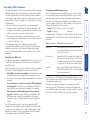
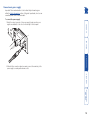
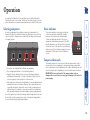
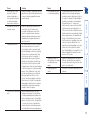
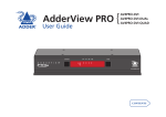
AdderView Secure } AVSD1002 (2 port) AVSD1004 (4 port) User Guide 1 2 3 4 ERR PWR Contents Locations.......................................................................................7 Cabling recommendations...........................................................7 Tamper-evident seals...................................................................7 Links overview..............................................................................7 Mounting......................................................................................8 Making connections.....................................................................9 Connections to computer systems ........................................9 Connections to user console peripherals..............................11 Video display (EDID) information.........................................13 Connection to power supply.................................................14 Troubleshooting.........................................................................16 Summary of threats and solutions.............................................16 Getting assistance.......................................................................18 Warranty.....................................................................................19 Safety information.....................................................................19 Radio Frequency Energy............................................................20 Further information Installation Selecting computers...................................................................15 Error indicator............................................................................15 Tamper-evident seals.................................................................15 Introduction..................................................................................3 AdderView Secure - features.......................................................4 Devices used with the AdderView Secure...................................5 Keyboard devices.....................................................................5 Mouse devices..........................................................................5 Standard items..............................................................................6 Additional items...........................................................................6 Operation Welcome IMPORTANT: Before using this product......................................2 1 Prior to use, a prospective user of the product should ensure that individuals with the appropriate authority implement the following objectives in the environment where the product is to be used: • The operational environment procedures must ensure that all users are duly authorized and possess the necessary privileges to access the information transferred via the product. This should be implemented physically and in terms of supporting IT infrastructure. • Operational procedures must (e.g. re staff vetting and training) ensure that, as far as is reasonably possible, the product is received, installed and managed in accordance with the manufacturer’s directions. This should also ensure that users are not malicious or hostile. • The product should be installed in an environment that is physically secure. Additionally, the security office in the organisation purchasing the product should be aware the product is not responsible for security vulnerabilities in computers, IT components or peripherals outside its physical boundary. The security of other system components connected to the product will require separate management to ensure IT security best practice. IMPORTANT: Before using this product 2 Welcome PC 1 2 3 PC 2 4 PC 3 PC 4 Individually colored indicators provide clear visual feedback about the currently selected channel. Channel switching is by physical button press only, no keyboard or mouse codes are permitted. Hard wired Data Diodes enforce a one-way flow on information. The switching section is hard wired to allow only one channel to be selected at any time. This operation is also closely monitored by separate checking circuitry. 1 Common keyboard, mouse, video monitor and speakers are able to access multiple high security computers/networks, safe in the knowledge that data will not be transferred from one to another, either by user error or subversive attack. Various strategies are employed to ensure complete separation between the switched channels: • One-way Data Diodes are used on keyboard and mouse communication channels so that data isolation does not rely on software. • The keyboard and mouse are powered down and re-initialized during every channel switch to ensure that they cannot act as transport media for malicious data between computers. • Many aspects of operation are internally monitored. For instance, if a second channel attempts to open while another is still active, all operation will be instantly halted and an error condition signalled to the user. The AdderView Secure range of products are highly robust KVMA switches for critical applications. When information absolutely must not be leaked between systems or networks, the AdderView Secure units combine the necessary isolation with a desirable ease of use. AdderView Secure units are available in two port and four port versions. Both models combine a number of overlapping strategies that are designed and proven to defeat potential points of infiltration or protect against user error. Firstly, all channel switching is controlled only from the front panel buttons. No keyboard or mouse switching commands are permitted and all operations are continually monitored by a dedicated sub-system. Any deviation from a strictly ordered sequence of events will result in an error condition, where all channels are immediately isolated and the operator is informed via a front panel indicator. Data Diodes, implemented within hardwired electronic circuitry, rather than software, are liberally employed to ensure that critical data paths can flow only in one direction. These data diodes ensure that a compromised peripheral, a keyboard for instance, cannot read information back from a connected system in order to transfer such details to another system. Whenever a channel is changed, the connected keyboard and mouse are always powered down and re-initialized to provide yet another level of protection against hidden peripheral malware. In general, the role of software within the unit has been reduced to an absolute minimum to avoid the possibility of subversive reprogramming. Additionally, all flash memory has been banished from the design, to be replaced by one-time programmable storage which cannot be altered. The outer casing contains extensive shielding to considerably reduce electromagnetic emissions. Additionally, the casing has been designed with as few apertures as possible to reduce the possibility of external probing and several primary chassis screws are concealed by tamper-evident seals to indicate any unauthorized internal access. Shielding extends also to the internal circuitry with all channels providing a minimum of 60dB crosstalk separation between computer input signals and any signals from the other computers at frequencies up to 100MHz. These are just a few of the many strategies and innovations that have been combined to ensure separation between differing systems. Numerous other defences lie in wait to defeat any potential threat. Introduction 3 AdderView Secure - features 2 3 4 ERR PWR Switching is controlled solely by the clearly labeled front panel buttons Each selected channel is represented by an individually colored indicator to provide additional visual feedback. 2 port version 2 3 2 1 5V 4 Clear and simple connections All connections are clearly marked to avoid any ambiguity. Full dual link DVI/I video connections are provided and USB connections are used throughout for keyboard and mouse links. 2.0A 2 port version 2 1 5V INDOOR USE ONLY USER CONSOLE INDOOR USE ONLY 1 1 Clear error indication Any unexpected operation (such as an attempt to select two channels simultaneously) will be signalled by the ERR indicator, accompanied by complete isolation of all channels. Secure and shielded casing The casing is shielded to reduce electromagnetic emissions to an absolute minimum, access apertures are minimized and vital access screws have tamper-evident seals. The AdderView Secure is housed in an electromagnetically shielded robust casing that measures just [w x d x h] 9.25” x 5.9” x 1.73” (235mm x 150mm x 44mm) - the height is 1U within a 19” rack. All channel switching is achieved solely using the front panel buttons which are clearly indicated, as are the rear panel connections. 2.0A 4 Devices used with the AdderView Secure Keyboard devices Although pointing devices don’t generally process confidential data and are therefore considered to pose a lower risk, you should ensure that the mouse used with the switch is approved against the security policy of your organization and plugged directly into the switch’s USB mouse port with no adapters or converters. The mouse is powered down and reset at every switchover to clear stored states. NS LE OL E USE RC ON USE RC ON SO LE 4 SO LE 3 4 2 3 1 2 1 5V 5V 2.0A 2.0A CO SO INDOOR USE ONLY ER INDOOR USE ONLY US ON ER C US Mouse devices The keyboard used with the switch must be approved against the security policy of your organization and must be plugged directly into the switch’s USB keyboard port with no adapters or converters. During the life of the product, the user should make periodic checks to ensure that the keyboard remains directly connected into the switch’s USB keyboard port. The keyboard is powered down and reset at every switchover to clear stored states. 5 Standard items Additional items Rack brackets Including four screws AdderView Secure unit AVSD1002 (2 port) AVSD1004 (4 port) 1 2 3 4 5V, 2A Power supply plus country-specific mains cable RP W R ER Installation CD-ROM 6 Installation The rear panel of the unit is well marked, however, the diagram below offers additional clarity on how best to arrange your connections. You may have noticed that the indicators on the front panel use different colors to represent the various channels. This is done to provide quick and effective visual feedback to the operator. Channel 1 has a green indicator and is traditionally used for the lowest security connection. The final channel, numbered 2 on the two port version and 4 of the four port version, uses a red indicator and is usually connected to the highest security connection. These are configuration conventions only and are offered as a suggestion - there are no technical differences in the operational specifications of the four channels. Please consider the following important points when planning the location of the AdderView Secure unit: • Situate the unit close to the host computers to which it will be connected and also the user console peripherals. • The unit requires a power supply input, so a nearby spare mains power outlet will be required. • As keyboard and mouse switching codes are not possible for security reasons, the only way to change channels is via the front panel buttons. Therefore, the unit should be easily accessible from the user’s normal position. • Please consult the precautions listed within the Safety information section. Links overview Locations Tamper-evident seals The primary casing access screws are pre-fitted with tamper-evident seals. It may be a policy of your organization to fit proprietary tamper-evident labels across certain chassis screws. Additionally, seals could be added between each connection and the unit to highlight any connections that have been altered. IMPORTANT: Do not use the unit if the tamper-evident seals are damaged. Do not use if there are any signs of damage to the unit or its power supply. 3 2 1 5V 2.0A Console connections Connect directly to the operator’s keyboard, mouse, video display and speakers. Channel 4 (red indicator) Usually used for connection to the highest security computer/ network. Channel 3 (amber indicator) Channel 2 (blue indicator or red indicator on two channel models) Channel 1 (green indicator) Usually used for connection to the lowest security computer/ network. 4 USER CONSOLE It is vitally important to use good quality shielded cables to minimize the risk of signal emissions that may be intercepted. Please follow the following recommendations when specifying cables: • DVI cables - should be braid and foil shielded. • VGA cables - should be braid and foil shielded. If DVI-I to VGA style adapters are used these should be of the fully ‘canned’ variety. • USB cables - should be braid and foil shielded. • Audio cables - should be braid shielded with fully shielded connectors (not unshielded connectors with drain wires). We strongly recommend that you fit ferrite cores at both ends of every cable to further assist with emission suppression. INDOOR USE ONLY Cabling recommendations 7 Mounting NS OL E 4 1 5V 2.0 A CO ER INDOOR USE ONLY US The AdderView Secure unit offers two main mounting methods: • Supplied four self-adhesive rubber feet • Optional rack brackets 8 Making connections Connections to computer systems 2 2.0 A 1 5V 2.0 A 2 At the rear panel of the unit, choose the appropriate channel group (1 to 4) and connect a USB link cable (square type-B plug) to the socket marked 3 Attach the other end of the USB link cable to a vacant USB socket of the appropriate host computer (this will most probably require a rectangular type-A USB plug). INDOOR USE ONLY 5V INDOOR USE ONLY 1 3 Attach the other end of the audio link cable to the speaker socket of the appropriate system. 2 To connect an audio link 1 Wherever possible, ensure that power is disconnected from the unit and the host computer(s) to be connected. 2 At the rear panel of the unit, choose the appropriate channel group (1 to 4) and connect an audio link cable to the socket marked To connect a keyboard and mouse link 1 Wherever possible, ensure that power is disconnected from the unit and the host computer(s) to be connected. Connections to the AdderView Secure unit do not need to follow the precise order given in this user guide, although if one or more systems must be hotplugged, connect these after all other connections have been made. IMPORTANT: All rear panel connectors are clearly marked, however, take great care not to cross connect any links or devices. You are recommended to connect all of the input and output links within one channel before proceeding to the next channel. Note: In order to minimize signal emissions, you are strongly recommended to use good quality shielded cables throughout and to fit ferrite cores at each end of every cable. 9 Connections to computer systems (continued) Connecting video inputs 5V 2.0 2 1 5V 2.0 A Digital video input Analog video input A INDOOR USE ONLY 1 To connect a video input 1 Wherever possible, ensure that power is disconnected from the unit and the host computer(s) to be connected. 2 As appropriate, connect either a digital or analog video link cable to the required DVI/I socket on the rear panel: • Digital Connect a digital video link cable to the port labeled within the appropriate channel group on the rear panel. • Analog Connect a converter module to the port labeled within the appropriate channel group on the rear panel. Connect an analog video link cable to the converter module. In both cases, ensure that the securing screws are used to maintain reliable links. 3 Connect the plug at the other end of the cable to the corresponding video output socket of the appropriate host computer. 2 INDOOR USE ONLY The unit provides full DVI/I connections for video. This means that it can receive, and transfer, any VGA or DVI input (from analog to single or dual link digital) up to the following maximum resolutions and rates: • Analog: 1920 x 1200 x 60Hz • Single link digital: 1920 x 1200 x 60Hz (up to 165MHz pixel clock) • Dual link digital: 2560 x 1600 x 60Hz (up to two times 165MHz pixel clock) Generally, all inputs should be of the same type, i.e. all analog or all digital (and the monitor should correspondingly be of the correct type). However, there are certain situations where mixing of different video types is possible - contact technical support for more details. The use of EDID information (automatically provided by the video display) could cause issues in certain high security installations - please see the Video display (EDID) information section for further details). 10 Connections to user console peripherals To connect speakers 1 Wherever possible, ensure that power is disconnected from the unit and the host computer(s) to be connected. 2 At the far left side of the rear panel, connect the speaker cable to the socket marked ER CO NS OL E NS OL E US CO ER US To connect a keyboard and mouse Note: The AdderView Secure unit can directly accommodate only a USB-style keyboard and mouse. If required, you can use suitably shielded conversion cables to connect peripherals that have PS/2-style interfaces. 1 Wherever possible, ensure that power is disconnected from the unit and the host computer(s) to be connected. 2 At the far left side of the rear panel, connect the cables from the keyboard and mouse to the USB sockets marked and respectively. 11 CO NS OL E ER US ER CO NS OL Digital video display output E To connect a video display 1 Wherever possible, ensure that power is disconnected from the unit and the host computer(s) to be connected. 2 As appropriate, connect either a digital or analog video display to the DVI/I socket on the far left side of the rear panel: • Digital Connect the digital video display cable to the port labeled within the user console section on the rear panel. • Analog Connect a converter module to the port labeled within the user console section on the rear panel. Connect the analog video display cable to the converter module. In both cases, ensure that the securing screws are used to maintain reliable links. 3 Connect the plug at the other end of the cable to the corresponding video output socket of the appropriate host computer. US Analog video display output The unit provides full DVI/I connections for video outputs. This means that it can transfer any VGA or DVI signal (from analog to single or dual link digital) up to the following maximum resolutions and rates: • Analog: 1920 x 1200 x 60Hz • Single link digital: 1920 x 1200 x 60Hz (up to 165MHz pixel clock) • Dual link digital: 2560 x 1600 x 60Hz (up to two times 165MHz pixel clock) Generally, all video signals should be of the same type, i.e. all analog or all digital (and the monitor should correspondingly be of the correct type). However, there are certain situations where mixing of different video types is possible - contact technical support for more details. The use of EDID information (automatically provided by the video display) could cause issues in certain high security installations - please see the Video display (EDID) information section for further details). Connecting video displays 12 Connected EDID information is harvested from the connected video display during unit power on and written to all computer port memories. Not connected Unit retains the EDID information that is already held in the port memories and continues to present them to the attached computers. No new EDID information can be sought from the currently connected video display. Grounded Unit overwrites all EDID information held in memory with default information but does not present anything to the attached computers. In situations where no EDID information is being supplied, it may be necessary to use a special driver on the connected computers to inform their graphic adapters on the appropriate signals to send. Alternatively, a ‘surrogate’ video display of the appropriate type could be temporarily connected to the AdderView Secure unit in order to harvest the necessary EDID information. The surrogate video display could then be replaced by the real one, which has its DDC pins disconnected (not grounded). AdderView Secure unit response DDC pin conditions AdderView Secure EDID policy The AdderView Secure maintains individual EDID memories for each connected computer port. During manufacture, these memories are each loaded with a default EDID packet. When the AdderView Secure is powered on, its response will be determined by the condition of the DDC signalling pins of the video monitor connector: • If the DDC pins are connected as standard: The AdderView Secure reads the EDID information from the attached video monitor and loads a copy into each port memory, which can then be made available to the connected computers. • If no video monitor is connected or the monitor’s DDC signalling pins are disconnected: The AdderView Secure will maintain the default data held in the EDID memories and make them available to the computers. • If the video monitor’s DDC signalling pins have been connected to ground: The AdderView Secure will load a set of default data to the EDID memories and no data will be made available to the computers. This provides a means of clearing information about previously attached monitors. Note: Most analog video cards will output a video signal without EDID information. In such installations it may be acceptable to disconnect the DDC connections from the AdderView Secure so that no EDID information is made available to the computers. However, some graphics cards will not output a video signal unless they can read the EDID information. To determine how EDID information is used Note: The information given here is provided purely as an overview. It is beyond the scope of this document to provide detailed instructions on how to modify video display cables, which should only be attempted by a qualified engineer. If the transfer of EDID information is unsuitable for your installation, you can take steps to bypass or disable its use. EDID information is sent from the video display on the following pins of their connectors: • Analog VGA (15-pin D-type) connector: pins 12 and 15 • Digital DVI connector: pins 6 and 7 As mentioned earlier, the AdderView Secure unit responds in the different ways, depending upon how the DDC data lines within the video display cable have been wired: The Display Data Channel (or DDC) scheme was introduced to allow analog and digital video displays to provide details (using the information format of EDID - Extended Display Identification Data) about themselves and their capabilities to the computer’s graphic adapter circuitry. In most applications this is a useful and positive feature. However, in a highly secure environment this presents two potential problems: • Most video displays provide manufacturer, model and serial number information as part of their EDID transfer. This unique information could possibly be used as a marker by anyone attempting to compromise security within one or more of the connected computers/networks. • The operation of the DDC scheme could theoretically provide a means to transfer a small packet of EDID information to the computers at each power on cycle of the AdderView Secure. If your organization wishes to protect against such scenarios then it is recommended that the DDC lines are disconnected in the cable between the AdderView Secure and the monitor. Alternatively, Adder would be happy to discuss configuring the AdderView Secure with a DDC policy to suit your organization. Video display (EDID) information 13 Connection to power supply To connect the power supply 1 Attach the output connector of the power supply (country specific power supplies are available) to the socket on the far right of the rear panel. 2 Important: Please read and adhere to the electrical safety information given within the Safety information section of this guide. In particular, do not use an unearthed power socket or extension cable. 2 When all other connections have been made, connect the main body of the power supply to a nearby earthed mains socket. A 2.0 5V INDOOR USE ONLY 1 14 Operation 2 3 4 Tamper-evident seals • The buttons are clearly labeled to eliminate any ambiguity. • Press the appropriate button to select the labeled channel. • When the chosen channel has been connected, the adjacent indicator will illuminate (continuously) to confirm. If the indicator flashes, then the selected computer is either switched off or disconnected. • Each channel uses a differently colored indicator to provide additional visual feedback about the chosen channel. Channel 1 has a green indicator and is generally configured to link with the lowest security computer/network, whereas channel 4 (or channel 2 on two-port versions) has a red indicator and is generally configured to link with the highest security computer/network. Note: If a keyboard key is held down during a channel change then the key will be sent to the selected computer upon release of the channel change button. Do not hold down keys during a channel change. The primary casing access screws are pre-fitted with tamper-evident seals. It may be a policy of your organization to fit proprietary tamper-evident labels across certain chassis screws. Additionally, seals could be added between each connection and the unit to highlight any connections that have been altered. IMPORTANT: Do not use the unit if the tamper-evident seals are damaged. Do not use if there are any signs of damage to the unit or its power supply. ERR PWR 1 The red error indicator is located on the right side of the front panel and is labeled ERR. Separate microprocessors monitor each channel and any of them can trigger an error state if they detect unexpected or unauthorized operations. If the ERR indicator illuminates, you will need to first locate and confirm the source of the fault. Then you will need to either power cycle the offending computer or remove and replace its USB connection to the AdderView Secure. Error indicator In order to guard against the possibility of malicious software and also to minimize the chance of accidental switching, the AdderView Secure unit offers only one method to change between channels. All switching is done using the front panel switches. Selecting computers In operation, the AdderView Secure unit allows you to quickly and securely switch between up to four systems. Strictly only one system may be accessed at a time, whereupon the common keyboard and mouse are linked to that system. 15 Further information Video from some computers only • Remember that the AdderView Secure does not convert digital video signals to analog signals and vice versa so it is not generally possible to mix digital and analog inputs. Mixed systems are possible in certain special circumstances but these will require specialist assistance from Adder technical support. Microprocessor malfunction or unanticipated software bugs causing data to flow between ports. Unidirectional data flow is enforced by hardware “data diodes” so data isolation doesn’t rely on software integrity. Subversive snooping by means of detecting electromagnetic radiation emitted from the equipment. Carefully shielded metal case with dual shielding in critical areas. Detection of signals on one computer by monitoring for crosstalk (leakage) signals on another computer. No connection to sensitive analogue inputs (such as computer microphone ports) are provided. A very high level of crosstalk separation is provided between signals from different computers. Malicious modification of microprocessor software causing data to leak between ports. Data isolation is assured by hardware and so is not compromised by any changes to the microprocessor software. Microprocessors use one time programmable memory so flash upgrades are not possible. Case uses counter-sunk screws which can be protected by tamper-evident seals. Buffered data within a keyboard or mouse is sent to the wrong computer after switchover. Keyboard and mouse are powered down and reset between each switchover to ensure that all buffers are cleared out. Data leakage by means of monitoring conducted emissions on mains power. The power circuitry provides strong protection against signal leakage via the power cable. Solution Threat No video from computer • This is most likely to be associated with a mismatch between the host computer’s video output and the DDC data held within the AdderView Secure. Computers often need read the correct DDC data before they will output a video signal. If digital DDC data is presented to a computer’s analog video port, a video signal will not be generated. Conversely, if analog DDC data is presented to a computer’s digital video port, a video signal will also not be generated. Depending on your DDC connection policy (see Video display (EDID) information for details), remember that the AdderView Secure will only attempt to read the EDID information from your monitor when the AdderView Secure is first powered on. To ensure that your monitor’s EDID information is read and stored correctly, ensure that it is attached and powered on when you switch on the AdderView Secure. This section provides a list of potential security threats that the AdderView Secure might face during operation and the special steps that have been taken to counteract them. If you experience problems when installing or using the AdderView Secure unit, please check through this section for a possible solution. If your problem is not listed here and you cannot resolve the issue, then please refer to the ‘Getting assistance’ section. Summary of threats and solutions Troubleshooting 16 Forced malfunctions due to overloaded signalling. Data transfer by means of common storage. USB ports support keyboard and mouse connections only. The product does not enable a USB memory stick or disk drive to be shared between computers. Unidirectional keyboard and mouse data signalling protects against data transfer across the switch. Timing analysis attacks. If a connection exists between a computer and a shared microprocessor system, it is potentially possible to determine what may be happening on the micro by timing the responses to repeated requests that the micro must service. For example, if a high data bit takes longer to transmit through the system than a low bit it may be possible to detect the pattern of data flowing between other ports by attempting to time the responses to otherwise normal requests. In the AdderView Secure, each port has a dedicated processor that only has input signals from the rest of the system. These input signals are only active when the port is selected. Consequently a timing analysis attack from one computer would yield no information about data flowing to another computer. It is potentially possible to create forced malfunctions by constantly and quickly sending a stream of valid requests (such as the request to update the keyboard lights). A well known example of an undesirable KVM malfunction is a “crazy mouse” which was quite common with early KVM switches and was caused by data loss on PS/2 systems with the result that the mouse darted around the screen randomly clicking and opening windows. The unidirectional design of the AdderView Secure ensures that the influence of signalling on one port cannot flow past the data diodes. This means that overload signalling on one port will not affect the operation of another port. USB signalling is not susceptible to the failure mechanism that caused the crazy mouse on PS/2 systems. Signalling by means of shorting the power supply or loading the power supply. Each port is independently powered by its USB port. Shorting the power supply on one port will not cause the power on other ports to be switched off. Tampering with the switch. The switch is fitted with tamper protection measures. The user selects the wrong port. Only one simple method of selecting computers is provided. The selected port is clearly and unambiguously indicated on the front panel by means of colored lights adjacent to each key switch. For high levels of security, the screens of high and low security computers should be arranged to look visibly different in general appearance. Channel switching is controlled by the front panel buttons only with all keyboard hotkey or mouse switching capabilities removed from the design. Data being sent to ports by means of faulty or subverted keyboards or mice causing the channel to switch and sending data in turn to each port. Threat Solution Threat 17 Getting assistance 01954 780081 +1 888 275 1117 • Phone in the UK: in the US: 01954 780044 +1 888 932 3337 in the UK: in the US: • Fax • Email – [email protected] • Adder Technology website – www.adder.com Check the Support section of our website for the latest solutions and driver files. If you are still experiencing problems after checking the list of solutions in the Troubleshooting section then we provide a number of other solutions: 18 • • • • • Adder Technology Ltd warrants that this product shall be free from defects in workmanship and materials for a period of two years from the date of original purchase. If the product should fail to operate correctly in normal use during the warranty period, Adder will replace or repair it free of charge. No liability can be accepted for damage due to misuse or circumstances outside Adder’s control. Also Adder will not be responsible for any loss, damage or injury arising directly or indirectly from the use of this product. Adder’s total liability under the terms of this warranty shall in all circumstances be limited to the replacement value of this product. If any difficulty is experienced in the installation or use of this product that you are unable to resolve, please contact your supplier. • • For use in dry, oil free indoor environments only. Warning - live parts contained within power adapter. No user serviceable parts within power adapter - do not dismantle. Plug the power adapter into a socket outlet close to the module that it is powering. Replace the power adapter with a manufacturer approved type only. Do not use the power adapter if the power adapter case becomes damaged, cracked or broken or if you suspect that it is not operating properly. Do not attempt to service the unit yourself. Not suitable for use in hazardous or explosive environments or next to highly flammable materials. Do not use the power adapter if the power adapter case becomes damaged, cracked or broken or if you suspect that it is not operating properly. If you use a power extension cable, make sure the total ampere rating of the devices plugged into the extension cable do not exceed the cable’s ampere rating. Also, make sure that the total ampere rating of all the devices plugged into the wall outlet does not exceed the wall outlet’s ampere rating. The power adapter can get warm in operation – do not situate it in an enclosed space without any ventilation. • • • • Warranty Safety information 19 Radio Frequency Energy All interface cables used with this equipment must be shielded in order to maintain compliance with radio frequency energy emission regulations and ensure a suitably high level of immunity to electromagnetic disturbances. This equipment generates, uses and can radiate radio frequency energy and if not installed and used properly, that is, in strict accordance with the manufacturer’s instructions, may cause interference to radio communication. It has been tested and found to comply with the limits for a class A computing device in accordance with the specifications in Subpart J of part 15 of FCC rules, which are designed to provide reasonable protection against such interference when the equipment is operated in a commercial environment. Operation of this equipment in a residential area may cause interference, in which case the user at his own expense will be required to take whatever measures may be necessary to correct the interference. Changes or modifications not expressly approved by the manufacturer could void the user’s authority to operate the equipment. This equipment does not exceed the class A limits for radio noise emissions from digital apparatus set out in the radio interference regulations of the Canadian Department of Communications. Le présent appareil numérique n’émet pas de bruits radioélectriques dépassant les limites applicables aux appareils numériques de la classe A prescrites dans le règlement sur le brouillage radioélectriques publié par le ministère des Communications du Canada. Canadian Department of Communications RFI statement This equipment has been tested and found to comply with the limits for a class A computing device in accordance with the specifications in the European standard EN55022. These limits are designed to provide reasonable protection against harmful interference. This equipment generates, uses and can radiate radio frequency energy and if not installed and used in accordance with the instructions may cause harmful interference to radio or television reception. However, there is no guarantee that harmful interference will not occur in a particular installation. If this equipment does cause interference to radio or television reception, which can be determined by turning the equipment on and off, the user is encouraged to correct the interference with one or more of the following measures: (a) Reorient or relocate the receiving antenna. (b) Increase the separation between the equipment and the receiver. (c) Connect the equipment to an outlet on a circuit different from that to which the receiver is connected. (d) Consult the supplier or an experienced radio/TV technician for help. FCC Compliance Statement (United States) European EMC directive 89/336/EEC 20 Tel: +65 6288 5767 Fax: +65 6284 1150 Adder Asia Pacific 6 New Industrial Road, Hoe Huat Industrial Building #07-01, Singapore 536199 Adder Corporation, 350R Merrimac Street, Newburyport, MA 01950, United States of America Tel: +1-888-932-3337 Fax: +1-888-275-1117 Adder Technology Limited, Technology House, Trafalgar Way, Bar Hill, Cambridge, CB23 8SQ, United Kingdom Tel: +44 (0)1954 780044 Fax: +44 (0)1954 780081 © 2010 Adder Technology Limited All trademarks are acknowledged. Release 2.2 December 2010 Part No. MAN-AVSD-ADDER Documentation by: www.ctxd.com 21