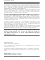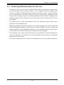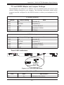
1
SUPER
®
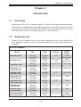
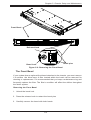
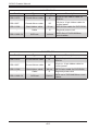
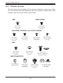
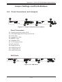
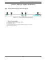
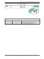
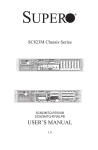
REAR VIEW
SC815 Chassis Series
FRONT VIEW
SC815TQ-720CB
SC815TQ-720UB
SC815TQ-710(V)(B)
SC815TQ-710U(B)
SC815TQ-710C(V)(B)
SC815S-700(V)(B)
SC815TQ-700(V)(B)
SC815S-700C(V)(B)
SC815TQ-700C(V)(B)
SC815S-R650C(V)(B)
SC815TQ-R650C(V)(B)
SC815S-560(V)(B)
SC815TQ-560(V)(B)
SC815S-560C(V)(B)
SC815TQ-560C(V)(B)
SC815TQ-R450U(V)(B)
SC815TQ-R650U(V)(B)
SC815TQ-560U(V)(B)
USER’S MANUAL
1.1a
SC815 Chassis Manual
The information in this User’s Manual has been carefully reviewed and is believed to be accurate.
The vendor assumes no responsibility for any inaccuracies that may be contained in this document,
makes no commitment to update or to keep current the information in this manual, or to notify any
person or organization of the updates. Please Note: For the most up-to-date version of this
manual, please see our web site at www.supermicro.com.
Super Micro Computer, Inc. ("Supermicro") reserves the right to make changes to the product
described in this manual at any time and without notice. This product, including software, if any,
and documentation may not, in whole or in part, be copied, photocopied, reproduced, translated or
reduced to any medium or machine without prior written consent.
IN NO EVENT WILL SUPERMICRO BE LIABLE FOR DIRECT, INDIRECT, SPECIAL, INCIDENTAL,
SPECULATIVE OR CONSEQUENTIAL DAMAGES ARISING FROM THE USE OR INABILITY TO
USE THIS PRODUCT OR DOCUMENTATION, EVEN IF ADVISED OF THE POSSIBILITY OF
SUCH DAMAGES. IN PARTICULAR, SUPERMICRO SHALL NOT HAVE LIABILITY FOR ANY
HARDWARE, SOFTWARE, OR DATA STORED OR USED WITH THE PRODUCT, INCLUDING THE
COSTS OF REPAIRING, REPLACING, INTEGRATING, INSTALLING OR RECOVERING SUCH
HARDWARE, SOFTWARE, OR DATA.
Any disputes arising between manufacturer and customer shall be governed by the laws of Santa
Clara County in the State of California, USA. The State of California, County of Santa Clara shall
be the exclusive venue for the resolution of any such disputes. Super Micro's total liability for all
claims will not exceed the price paid for the hardware product.
California Best Management Practices Regulations for Perchlorate Materials: This Perchlorate
warning applies only to products containing CR (Manganese Dioxide) Lithium coin cells. “Perchlorate
Material-special handling may apply. See www.dtsc.ca.gov/hazardouswaste/perchlorate”
WARNING: Handling of lead solder materials used in this
product may expose you to lead, a chemical known to
the State of California to cause birth defects and other
reproductive harm.
Manual Revision 1.1a
Release Date: November 18, 2009
Unless you request and receive written permission from Super Micro Computer, Inc., you may not
copy any part of this document.
Information in this document is subject to change without notice. Other products and companies
referred to herein are trademarks or registered trademarks of their respective companies or mark
holders.
Copyright © 2009 by Super Micro Computer, Inc.
All rights reserved.
Printed in the United States of America
ii
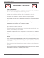
Preface
Preface
About This Manual
This manual is written for professional system integrators and PC technicians. It
provides information for the installation and use of the SC815 1U chassis. Installation and maintenance should be performed by experienced technicians only.
Supermicro's SC815 1U chassis features a unique and highly-optimized design for
Xeon and Opteron platforms. The chassis is equipped with a 450W, 560W, 650W
700W or 710W high efficiency power supply, or Gold Level 720W system for superb
power savings. High-performance fans provide ample optimized cooling, latest
generation memory modules and 4 hot-swappable 3.5" drive bays offers maximum
storage capacity in a 1U form factor. Optional LCD front bezels are also available
for customization requirements. Bulk package and quick release slide rails are
available for HPC and datacenter use.
This document lists compatible parts available when this document was published.
Always refer to the our Web site for updates on supported parts and configurations.
iii
SC815 Chassis Manual
Manual Organization
Chapter 1: Introduction
The first chapter provides a checklist of the main components included with this
chassis and describes the main features of the SC815 chassis. This chapter also
includes contact information.
Chapter 2: System Safety
This chapter lists warnings, precautions, and system safety. You should thoroughly
familiarize yourself with this chapter for a general overview of safety precautions
that should be followed before installing and servicing this chassis.
Chapter 3: Chassis Components
Refer here for details on this chassis model including the fans, bays, airflow shields,
and other components.
Chapter 4: System Interface
Refer to this chapter for details on the system interface, which includes the functions
and information provided by the control panel on the chassis as well as other LEDs
located throughout the system.
Chapter 5: Chassis Setup and Installation
Refer to this chapter for detailed information on this chassis. You should follow the
procedures given in this chapter when installing, removing, or reconfiguring your
chassis.
Chapter 6: Rack Installation
Refer to this chapter for detailed information on chassis rack installation. You should
follow the procedures given in this chapter when installing, removing or reconfiguring
your chassis into a rack environment.
Appendices
This section lists compatible cables, power supply specifications, and compatible
backplanes. Not all compatible backplanes are listed. Refer to our Web site for the
latest compatible backplane information.
Appendix A: Chassis Cables
Appendix C: Power Supply Specifications
Appendix C: SAS-815TQ Backplane Specifications
Appendix D: SCA-813S Backplane Specifications
iv
Preface
Table of Contents
Preface
About This Manual......................................................................................................... iii
Chapter 1 Introduction
1-1
Overview.......................................................................................................... 1-1
1-2
Shipping List..................................................................................................... 1-1
1-3
Chassis Features............................................................................................. 1-3
CPU.................................................................................................................. 1-3
Hard Drives...................................................................................................... 1-3
I/O Expansion slots.......................................................................................... 1-3
Peripheral Drives.............................................................................................. 1-3
Other Features................................................................................................. 1-3
1-4
Contacting Supermicro..................................................................................... 1-4
1-5
Returning Merchandise for Service................................................................. 1-5
Chapter 2 System Safety
2-1
Overview.......................................................................................................... 2-1
2-2
Warnings and Precautions............................................................................... 2-1
2-3
Preparing for Setup.......................................................................................... 2-1
2-4
Electrical Safety Precautions........................................................................... 2-2
2-5
General Safety Precautions............................................................................. 2-3
2-6
System Safety.................................................................................................. 2-3
Chapter 3 Chassis Components
3-1
Overview.......................................................................................................... 3-1
3-2
Components..................................................................................................... 3-1
Chassis............................................................................................................. 3-1
Backplane......................................................................................................... 3-1
Fans................................................................................................................. 3-1
Mounting Rails................................................................................................. 3-1
Power Supply................................................................................................... 3-2
Air Shroud........................................................................................................ 3-2
3-3
Where to get Replacement Components......................................................... 3-2
Chapter 4 System Interface
4-1
Overview.......................................................................................................... 4-1
4-2
Control Panel Buttons...................................................................................... 4-2
4-3
Control Panel LEDs......................................................................................... 4-3
4-4
Drive Carrier LEDs........................................................................................... 4-4
SAS/SATA Drives............................................................................................. 4-4
v
SC815 Chassis Manual
SCSI Drives...................................................................................................... 4-5
4-5
Power Supply LEDs and Overheat Indicators................................................. 4-5
450W and 650W Power Supplies.................................................................... 4-5
All Other Power Supplies................................................................................. 4-6
4-6
Overheating...................................................................................................... 4-6
Chapter 5 Chassis Setup and Maintenance
5-1
Overview.......................................................................................................... 5-1
5-2
Installation Procedures..................................................................................... 5-1
General Maintenance....................................................................................... 5-1
5-3
Removing the Chassis Cover and Front Bezel............................................... 5-2
5-4
Installing Hard Drives....................................................................................... 5-4
5-5
DVD and Floppy Drive Installation................................................................... 5-7
5-6
Installing the Motherboard............................................................................... 5-8
The Front Bezel............................................................................................... 5-3
Permanent and Optional Standoffs.................................................................. 5-8
Expansion Card Setup................................................................................... 5-10
5-7
Installing the Air Shroud................................................................................. 5-12
5-8
System Fans.................................................................................................. 5-14
5-9
Power Supply . .............................................................................................. 5-16
Power Supply Failure..................................................................................... 5-16
5-10 Routing the I2C Cables.................................................................................. 5-18
Chapter 6 Rack Installation
6-1
Overview.......................................................................................................... 6-1
6-2
Unpacking the System..................................................................................... 6-1
6-3
Preparing for Setup.......................................................................................... 6-1
Choosing a Setup Location.............................................................................. 6-1
Rack Precautions............................................................................................. 6-2
General Server Precautions............................................................................. 6-2
Rack Mounting Considerations........................................................................ 6-3
Ambient Operating Temperature................................................................. 6-3
Reduced Airflow.......................................................................................... 6-3
Mechanical Loading.................................................................................... 6-3
Circuit Overloading...................................................................................... 6-3
Reliable Ground.......................................................................................... 6-3
6-4
Rack Mounting Instructions.............................................................................. 6-4
Identifying the Sections of the Rack Rails....................................................... 6-4
Inner Rail Extension......................................................................................... 6-5
Installing the Chassis into a Telco rack........................................................... 6-9
vi
Preface
Appendix A Chassis Cables
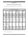
Appendix B SC815 Power Supply Specifications
Appendix C SAS-815TQ Backplane Specifications
Appendix D SCA-813S Backplane Specifications
vii
SC815 Chassis Manual
Notes
viii
Chapter 1: Introduction
Chapter 1
Introduction
1-1 Overview
Supermicro’s SC815 1U chassis features a unique and highly-optimized design.
The chassis is equipped with a high efficiency power supply. High performance fans
provide ample optimized cooling for FB-DIMM memory modules and four hot-swap
drive bays offer maximum storage capacity in a 1U form factor.
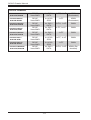
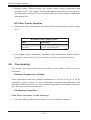
1-2 Shipping List
Please visit the following link for the latest shipping lists and part numbers for
your particular chassis model http://www.supermicro.com/products/chassis/1U/
?chs=815
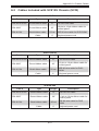
SC815 Chassis
Model
Power
Supply
CPU
HDD
I/O Slots
SC815TQ-720UB
DP/UP
Xeon/AMD
4x SAS /
SATA
1xFF
720W
(Gold Level)
SC815TQ-720CB
DP/UP
Xeon/AMD
4x SAS /
SATA
1xFF, 1xLP,
1 UIO
720W
(Gold Level)
• SC815TQ-710UB
DP/UP
Xeon/AMD
4x SAS /
SATA
2x FH, 1x LP
710W (DC)
• SC815TQ-710V /
SC815TQ-710B
DP/UP
Xeon/AMD
4x SAS /
SATA
1x FF, 1x LP
710W (DC)
• SC815S-710CV /
SC815S-710CB
DP/UP
Xeon/AMD
4x U320
SCSI
1x FF
710W (DC)
• SC815TQ-700V /
SC815TQ-700B
DP/UP
Xeon/AMD
4x SAS /
SATA
1x FF, 1x LP
700W
• SC815TQ-700CV /
SC815TQ-700CB
DP/UP
Xeon/AMD
4x SAS /
SATA
1x FF
700W
• SC815S-700V /
SC815S-700B
DP/UP
Xeon/AMD
4x U320
SCSI
1x FF, 1x LP
700W
• SC815S-700CV /
SC815S-700CB
DP/UP
Xeon/AMD
4x U320
SCSI
1x FF
700W
• SC815TQ-R650UV /
SC815TQ-R650UB
DP/UP
Xeon/AMD
4x SAS /
SATA
2x FH, 1x LP
650W
(Redundant)
1-1
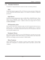
SC815 Chassis Manual
SC815 Chassis
• SC815TQ-R650V /
SC815TQ-R650B DP/UP
Xeon/AMD
4x SAS /
SATA
1x FF, 1x LP
650W
(Redundant)
• SC815S-R650V /
SC815S-R650B
DP/UP
Xeon/AMD
4x U320
SCSI
1x FF
650W
(Redundant)
• SC815TQ-560UV /
SC815TQ-560UB
DP/UP
Xeon/AMD
4x SAS /
SATA
2x FH, 1x LP
560W
• SC815TQ-560V /
SC815TQ-560B
DP/UP
Xeon/AMD
4x SAS /
SATA
1x FF, 1x LP 560W
• SC815TQ-560CV /
SC815TQ-560CB
DP/UP
Xeon/AMD
4x SAS /
SATA
1x FF
560W
• SC815S-560V /
SC815S-560B
DP/UP
Xeon/AMD
4x U320
SCSI
1x FF, 1x LF
560W
• SC815S-560CV /
SC815S-560CB
DP/UP
Xeon/AMD
4x U320
SCSI
1x FF
560W
• SC815TQ-R450UV /
SC815TQ-R450UB
DP/UP
Xeon/AMD
4x SAS /
SATA
2x FH, 1x LP
450W (Redundant)
1-2
Chapter 1: Introduction
1-3 Chassis Features
The SC815 1U high performance chassis includes the following features:
CPU
The SC815 chassis supports a DP or UP Dual-core Xeon processor. Please refer
to the motherboard specifications pages on our website for updates on supported
processors.
Hard Drives
The SC815 chassis features four slots for U320 SCSI or SAS/SATA drives. These
drives are hot swappable. Once setup correctly, these drives can be removed
without powering down the server. In addition, these drives support SAF-TE (SCSI)
or SES2 (SAS/SATA).
I/O Expansion slots
Each version of the SC815 chassis includes one full I/O expansion slot and one low
profile I/O slot "C" versions include only the full I/O expansion slot. "U" versions
are optimized for UIO mother boards and include two full I/O expansion slots and
one low profile expansion slot.
Peripheral Drives
Each SC815 chassis supports one slim DVD-ROM Drive (included) and one slim
floppy drive (optional). These drives allow you to quickly install or save data. Both
DVD drive and floppy drives are optional in 560W models.
Other Features
Other onboard features are included to promote system health. These include
various four cooling fans, a convenient power switch, reset button, and five LED
indicators.
1-3
SC815 Chassis Manual
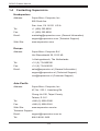
1-4 Contacting Supermicro
Headquarters
Address:
Super Micro Computer, Inc.
980 Rock Ave.
San Jose, CA 95131 U.S.A.
Tel:
+1 (408) 503-8000
Fax:
+1 (408) 503-8008
Email:
[email protected] (General Information)
[email protected] (Technical Support)
Web Site:
www.supermicro.com
Europe
Address:
Super Micro Computer B.V.
Het Sterrenbeeld 28, 5215 ML
's-Hertogenbosch, The Netherlands
Tel:
+31 (0) 73-6400390
Fax:
+31 (0) 73-6416525
Email:
[email protected] (General Information)
[email protected] (Technical Support)
[email protected] (Customer Support)
Asia-Pacific
Address:
Super Micro Computer, Inc.
4F, No. 232-1, Liancheng Rd.
Chung-Ho 235, Taipei County
Taiwan, R.O.C.
Tel:
+886-(2) 8226-3990
Fax:
+886-(2) 8226-3991
Web Site:
www.supermicro.com.tw
Technical Support:
Email:
[email protected]
Tel: 886-2-8226-1900
1-4
Chapter 1: Introduction
1-5 Returning Merchandise for Service
A receipt or copy of your invoice marked with the date of purchase is required before any warranty service will be rendered. You can obtain service by calling your
vendor for a Returned Merchandise Authorization (RMA) number. When returning
to the manufacturer, the RMA number should be prominently displayed on the
outside of the shipping carton, and mailed prepaid or hand-carried. Shipping and
handling charges will be applied for all orders that must be mailed when service
is complete.
For faster service, RMA authorizations may be requested online (http://www.
supermicro.com/support/rma/).
Whenever possible, repack the chassis in the original Supermicro carton, using the
original packaging material. If these are no longer available, be sure to pack the
chassis securely, using packaging material to surround the chassis so that it does
not shift within the carton and become damaged during shipping.
This warranty only covers normal consumer use and does not cover damages incurred in shipping or from failure due to the alteration, misuse, abuse or improper
maintenance of products.
During the warranty period, contact your distributor first for any product problems.
1-5
SC815 Chassis Manual
Notes
1-6
Chapter 2: System Safety
Chapter 2
System Safety
2-1 Overview
This chapter provides a quick setup checklist to get your chassis up and running.
Following the steps in order given should enable you to have your chassis setup and
operational within a minimal amount of time. This quick set-up assumes that you are
an experienced technician, famailiar with common concepts and terminology.
2-2 Warnings and Precautions
You should inspect the box the chassis was shipped in and note if it was damaged
in any way. If the chassis itself shows damage, file a damage claim with carrier
who delivered your system.
Decide on a suitable location for the rack unit that will hold that chassis. It should
be situated in a clean, dust-free area that is well ventilated. Avoid areas where heat,
electrical noise and electromagnetic fields are generated.
You will also need it placed near at least one grounded power outlet. When configured, the SC815 chassis includes one power supply. "R" models include a redundant
power supply and require two grounded outlets.
2-3 Preparing for Setup
The SC815 chassis includes a set of rail assemblies, including mounting brackets
and mounting screws you will need to install the systems into the rack. Please read
this manual in its entirety before you begin the installation procedure.
2-1
SC815 Chassis Manual
2-4 Electrical Safety Precautions
Basic electrical safety precautions should be followed to protect yourself from harm
and the SC815 from damage:
•Be aware of the locations of the power on/off switch on the chassis as well
as the room’s emergency power-off switch, disconnection switch or electrical
outlet. If an electrical accident occurs, you can then quickly remove power from
the system.
•Do not work alone when working with high-voltage components.
•Power should always be disconnected from the system when removing or in-
stalling main system components, such as the serverboard, memory modules
and the DVD-ROM and floppy drives (not necessary for hot swappable drives).
When disconnecting power, you should first power down the system with the
operating system and then unplug the power cords from all the power supply
modules in the system.
•When working around exposed electrical circuits, another person who is fa-
miliar with the power-off controls should be nearby to switch off the power, if
necessary.
•Use only one hand when working with powered-on electrical equipment. This
is to avoid making a complete circuit, which will cause electrical shock. Use
extreme caution when using metal tools, which can easily damage any electrical
components or circuit boards they come into contact with.
•Do not use mats designed to decrease electrostatic discharge as protection from
electrical shock. Instead, use rubber mats that have been specifically designed
as electrical insulators.
•The power supply power cord must include a grounding plug and must be
plugged into grounded electrical outlets.
•Serverboard Battery: CAUTION - There is a danger of explosion if the onboard
battery is installed upside down, which will reverse its polarities This battery
must be replaced only with the same or an equivalent type recommended by
the manufacturer. Dispose of used batteries according to the manufacturer’s
instructions.
•DVD-ROM laser: CAUTION - this server may have come equipped with a
DVD-ROM drive. To prevent direct exposure to the laser beam and hazardous
2-2
Chapter 2: System Safety
radiation exposure, do not open the enclosure or use the unit in any unconventional way.
2-5 General Safety Precautions
•Keep the area around the chassis clean and free of clutter.
•Place the chassis top cover and any system components that have been re-
moved away from the system or on a table so that they won’t accidentally be
stepped on.
•While working on the system, do not wear loose clothing such as neckties and
unbuttoned shirt sleeves, which can come into contact with electrical circuits or
be pulled into a cooling fan.
•Remove any jewelry or metal objects from your body, which are excellent metal
conductors that can create short circuits and harm you if they come into contact
with printed circuit boards or areas where power is present.
•After accessing the inside of the system, close the system back up and secure
it to the rack unit with the retention screws after ensuring that all connections
have been made.
2-6 System Safety
Electrostatic discharge (ESD) is generated by two objects with different electrical
charges coming into contact with each other. An electrical discharge is created to
neutralize this difference, which can damage electronic components and printed
circuit boards. The following measures are generally sufficient to neutralize this
difference before contact is made to protect your equipment from ESD:
•Do not use mats designed to decrease electrostatic discharge as protection from
electrical shock. Instead, use rubber mats that have been specifically designed
as electrical insulators.
•Use a grounded wrist strap designed to prevent static discharge.
•Keep all components and printed circuit boards (PCBs) in their antistatic bags
until ready for use.
2-3
SC815 Chassis Manual
•Touch a grounded metal object before removing any board from its antistatic
bag.
•Do not let components or PCBs come into contact with your clothing, which may
retain a charge even if you are wearing a wrist strap.
•Handle a board by its edges only; do not touch its components, peripheral chips,
memory modules or contacts.
•When handling chips or modules, avoid touching their pins.
•Put the serverboard and peripherals back into their antistatic bags when not
in use.
•For grounding purposes, make sure your computer chassis provides excellent
conductivity between the power supply, the case, the mounting fasteners and
the serverboard.
2-4
Chapter 3: Chassis Components
Chapter 3
Chassis Components
3-1 Overview
This chapter describes the most common components included with your chassis.
Some components listed may not be included or compatible with your particular
chassis model. For more information, see the installation instructions detailed later
in this manual.
3-2 Components
Chassis
Chassis include one slim CD-ROM bay, one slim floppy disc drive bay, and/or four
hard drive bays. Most chassis models include a DVD-ROM. Floppy disk drives and
hard drives must be purchased separately. For the latest shipping lists, visit our
Web site at: http://www.supermicro.com.
This chassis accepts a 1U backplane, four fans (with an optional fifth fan) and one
(sometimes two) power supplies. SC815 models come in silver and black.
Backplane
Each SC815 chassis comes with a 1U backplane. Depending on our order, you
backplane will accept SAS/SATA or SCSI. For more information regarding compatible backplanes, view the appendices found at the end of this manual. In addition,
visit our Web site for the latest information: http://www.supermicro.com.
Fans
The SC815 chassis accepts four system fans with an optional fifth fan. System fans
for SC815 chassis are powered from the serverboard. These fans are 1U high and
are powered by 3-pin connectors.
Mounting Rails
The SC815 can be placed in a rack for secure storage and use. To setup your rack,
follow the step-by-step instructions included in this manual.
3-1
SC815 Chassis Manual
Power Supply
Each SC815 chassis model includes a high-efficiency power supply rated between
450, 560, 650, 700, 710 or 720 Watts. In the unlikely event that your power supply
fails, replacement is simple and can be done without tools.
"R" model chassis include a redundant, hot-swappable power supply.
Air Shroud
Air shrouds are shields, usually plastic, that funnel air directly to where it is needed.
Always use the air shroud included with your chassis.
3-3 Where to get Replacement Components
Though not frequently, you may need replacement parts for your system. To ensure the highest level of professional service and technical support, we strongly
recommend purchasing exclusively from our Supermicro Authorized Distributors /
System Integrators/Resellers. A list of Supermicro Authorized Distributors/System
Integrators/Reseller can be found at: http://www.supermicro.com. Click the Where
to Buy link.
3-2
Chapter 4: System Interface
Chapter 4
System Interface
4-1 Overview
There are several LEDs on the control panel and on the drive carriers that provide
system and component status. This chapter explains the meanings of all LED indicators and the appropriate responses that need to be taken.
Figure 4-1. Control Panel Buttons and LEDs
4-1
SC815 Chassis Manual
4-2 Control Panel Buttons
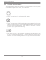
The SC815 chassis includes two or three push-buttons located on the front panel:
a reset button, a power on/off button, and a UID button
•Reset: The reset button is used to reboot the system.
•Power: The main power switch is used to apply or remove power from the power
supply to the server system. Turning off system power with this button removes
the main power but keeps standby power supplied to the system. Therefore,
you must unplug system before servicing.
•UID: When used with a UID-compatible motherboard, the UID button is used
to turn on or off the blue light function of the the U-LED. Once the blue light is
activated, the unit can be easily located in very large racks and server banks.
4-2
Chapter 4: System Interface
4-3 Control Panel LEDs
The control panel located on the front of the SC815 chassis has up to five LEDs.
These LEDs provide critical information related to different parts of the system.
This section explains what each LED indicates when illuminated and any action
that may be required.
•Universal Information LED: The Universal Information LED is used to indated
fan failure, power failure, overheat condition, or to identify the unit within a large
rack installation. The feature requires a motherboard that supports the Universal
Information LED.
When this LED blinks red quickly, it indicates a fan failure and when blinking red
slowly a power failure. This LED will be blue when used for UID (Unit Identifier).
When on continuously red, it indicates an overheat condition, which may be caused
by cables obstructing the airflow in the system or the ambient room temperature
being too warm. See the table below for descriptions of the LED states.
Universal Information LED States
State
Indication
Fast Blinking Red (1x/sec)
Fan Fail
Solid Red
CPU Overheat
Slow Blinking Red (1x/4 sec)
Power Fail
Solid Blue
Local UID Button Depressed
Blinking Blue
IPMI-Activated UID
Figure 4-2: Universal Information LED States
Note: Deactivating the UID LED must be performed in the same way it was activated. (If the UID LED was activated via IPMI, you can only turn the LED off via
IPMI and not with the UID button.)
•Overheat/Fan Fail: When this LED flashes it indicates a fan failure. When
continuously on (not flashing) it indicates an overheat condition, which may be
caused by cables obstructing the airflow in the system or the ambient room
temperature being too warm.
4-3
SC815 Chassis Manual
•NIC2: Indicates network activity on GLAN2 when flashing.
•NIC1: Indicates network activity on GLAN1 when flashing.
•HDD: Indicates IDE channel activity. SAS/SATA drive, SCSI drive, and/or DVDROM drive activity when flashing.
•Power: Indicates power is being supplied to the system's power supply units.
This LED should normally be illuminated when the system is operating.
4-4 Drive Carrier LEDs
Your chassis uses SAS/SATA or SCSI drives, but not both.
SAS/SATA Drives
Each SAS/SATA drive carrier has two LEDs.
•Green: Each Serial ATA drive carrier has a green LED. When illuminated, this
green LED (on the front of the SATA drive carrier) indicates drive activity. A con-
4-4
Chapter 4: System Interface
nection to the SATA backplane enables this LED to blink on and off when that
particular drive is being accessed.
•Red: The red LED to indicate an SAS/SATA drive failure. If one of the SAS/SATA
drives fail, you should be notified by your system management software.
SCSI Drives
Each SCSI drive carrier has two LEDs.
•Green: When illuminated, the green LED on the front of the SCSI drive carrier
indicates drive activity. A connection to the SCSI SCA backplane enables this
LED to blink on and off when that particular drive is being accessed.
•Red: The SAF-TE compliant backplane activates the red LED to indicate a drive
failure. If one of the SCSI drives fail, you should be notified by your system
management software.
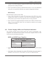
4-5 Power Supply LEDs and Overheat Indicators
This chassis provides several options which may include hot-swappable, coldswappable, and redundant power supplies. Some power supplies include an LED
in the rear with the following definitions:
450W and 650W Power Supplies
450W and 650W Power Supply LEDs
State
Indication
Solid Green
System is on.
Solid Amber
System is off and plugged in.
Blinking Amber
Internal temperature has reached 63C
and will shut down if the tempertature
reaches 70C.
•Solid Green: When illuminated, the green LED indicates that the power supply
is on.
•Solid Amber: When illuminated, the amber LED indicates the power supply is
plugged in and turned off, or the system is off but in an abnormal state.
4-5
SC815 Chassis Manual
•Blinking Amber: When blinking, this system power supply temperature has
reached to 63C. The system automatically power down when the power supply temperature reaches 70C and restarts when the power supply temperature
goes below 60C.
All Other Power Supplies
•Solid Green: When illuminated, this green LED indicates that the power supply
is on.
All Other Power Supply LEDs
State
Indication
Solid Green
System is on.
Solid Amber
System is off and plugged in.
•Solid Amber: When illuminated, the amber LED indicates the power supply is
plugged in and turned off, or the system is off but in an abnormal state.
4-6 Overheating
The section lists actions that should be taken in the unlikely event the server
overheats.
Overheat Temperature Setting
Some backplanes allow the overheat temperature to be set at 45, 50, or 55 by
changing a jumper setting. For more information, download the backplane user
manual at www.supermicro.com. To access the manuals on the Website, click support, and then click the manuals link.
Overheating Condition
If the Server Overheats, do the Following:
1. Use the LEDs to determine the nature of the overheating condition.
4-6
Chapter 4: System Interface
2. Confirm that the chassis covers are installed properly.
3. Check the routing of the cables and make sure all fans are present and operating normally.
4. Verify that the heatsinks are installed properly.
4-7
SC815 Chassis Manual
Notes
4-8
Chapter 5: Chassis Setup and Maintenance
Chapter 5
Chassis Setup and Maintenance
5-1 Overview
This chapter covers the steps required to install components and perform maintenance on the chassis. The only tool you will need to install components and perform
maintenance is a Phillips screwdriver. Print this page to use as a reference while
setting up your chassis.
5-2 Installation Procedures
Removing the Chassis Cover and Front Bezel
Installing Hard Drives
DVD and Floppy Drive Installation
Installing the Motherboard (includes U I/O Slot Setup)
Installing the Air Shroud and Check Airflow
General Maintenance
General Maintenance: Systems Fans
General Maintenance: Replace Power Supply
!
Review the warnings and precautions listed in the manual before setting up or servicing this chassis. These include information in Chapter 2: System Safety and the warning/precautions listed in the setup instructions.
5-1
SC815 Chassis Manual
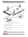
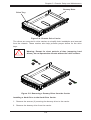
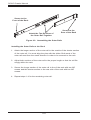
5-3 Removing the Chassis Cover and Front Bezel
3
1
1
2
Remove this screw
(if necessary)
Release Tab
Figure 5-1: Removing the Chassis Cover
Removing the Chassis Cover
1. Press the release tabs to remove the cover from the locked position. Press
both tabs at the same time.
2. Once the top cover is released from the locked position, slide the cover
toward the rear of the chassis.
3. Lift the cover off the chassis.
!
Warning: Except for short periods of time, do NOT operate the
server without the cover in place. The chassis cover must be
in place to allow proper airflow and prevent overheating.
5-2
Chapter 5: Chassis Setup and Maintenance
Front Bezel
Release Knob
Bezel pins
Bezel Lock
Figure 5-2: Removing the Front Bezel
The Front Bezel
If your system has an optional front bezel attached to the chassis, you must remove
it to access the drive bays. A filter located within the bezel can be removed for
cleaning or replacement. It is recommended that you keep a maintenance log and
frequently replace the filter. The filter's condition will affect the airflow throughout
the whole system.
Removing the Front Bezel
1. Unlock the bezel lock.
2. Press the release knob to retract the bezel pins
3. Carefully remove the bezel with both hands.
5-3
SC815 Chassis Manual
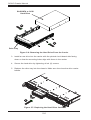
5-4 Installing Hard Drives
2
1
Figure 5-3: Removing Hard Drive Carriers
Removing Hard Drive Carriers from the Chassis
1. Press the release button on the drive carrier. This extends the drive carrier
handle.
2. Use the handle to pull the drive carrier out of the chassis.
5-4
Chapter 5: Chassis Setup and Maintenance
Dummy Drive
Drive Tray
Figure 5-4: Chassis Drive Carrier
The drives are mounted in drive carriers to simplify their installation and removal
from the chassis. These carriers also help promote proper airflow for the drive
bays.
!
Warning: Except for short periods of time (swapping hard
drives), do not operate the chassis without the drive carriers.
1
1
Figure 5-5: Removing a Dummy Drive from the Carrier
Installing a Hard Drive to the Hard Drive Carrier
1. Remove the screws (2) securing the dummy drive to the carrier.
2. Remove the dummy drive from the carrier.
5-5
SC815 Chassis Manual
SAS/SATA or SCSI
Hard Drive
4
4
Drive Tray
Figure 5-6: Removing the Hard Drive From the Carrier
3. Install a new drive into the carrier with the printed circuit board side facing
down so that the mounting holes align with those in the carrier.
4. Secure the hard drive by tightening all six (6) screws.
5. Replace the drive tray into the chassis. Make sure the close the drive carrier
handle.
5
Figure 5-7: Replacing the Hard Drive Carrier
5-6
Chapter 5: Chassis Setup and Maintenance
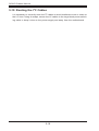
5-5 DVD and Floppy Drive Installation
Most SC815 chassis models include a DVD-ROM and space for an optional floppy
drive. The DVD-ROM is usually pre-installed.
Installing or Replacing a DVD-ROM or Floppy Drive
1. Power down the system and if necessary, remove the server from the rack
and the front bezel from the chassis.
2. Remove the chassis cover.
3. Unplug the drives power and data cables from the motherboard and/or backplane.
4. If you are adding a new drive: Remove the mini-bezel (grate) from the drive
bay The bezel can be removed by pulling out the hard drive beneath the
DVD-ROM or floppy drive bay, then pulling the mini-bezel forward.
If you are replacing a drive: Locate the locking tab at the rear (left hand side
when viewed from the front) of the DVD-ROM or floppy drive. Push the tab
toward the drive and push the drive unit out the front of the chassis.
5. Insert the new drive unit in the slot until the tab locks in place.
6. Reconnect the data and power cables.
7. Replace the chassis cover (replace the server in the rack, if necessary) and
power up the system.
5-7
SC815 Chassis Manual
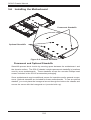
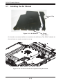
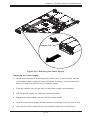
5-6 Installing the Motherboard
Permanent Standoffs
Optional Standoffs
Figure 5-8: Chassis Standoffs
Permanent and Optional Standoffs
Standoffs prevent short circuits by securing space between the motherboard and
the chassis surface. The SC815 chassis includes permanent standoffs in locations
used by most motherboards. These standoffs accept the rounded Phillips head
screws included in the SC815 accessories packaging.
Some motherboards require additional screws for heatsinks and/or general components. Optional standoffs are included for these motherboards. To use an optional
standoff, you must place the hexagonal screw through the bottom the chassis and
secure the screw with the hexagonal nut (rounded side up).
5-8
Chapter 5: Chassis Setup and Maintenance
Installing the Motherboard
1. Review the documentation that came with your motherboard. Become familiar with component placement, requirements, and precautions.
2. Disconnect the power supply and lay the chassis on a flat surface.
3. Open the chassis cover.
4. If necessary, remove the riser card. To do this, remove the two screws holding the card in place and lift the card from the chassis.
5. As required by your motherboard, install standoffs in any areas that do not
have a permanent standoff:
A. Place a hexagonal standoff screw through the bottom the chassis.
B. Secure the screw with the hexagonal nut (rounded side up).
6. Lay the motherboard on the chassis aligning the permanent and optional
standoffs
7. Secure the motherboard to the chassis using the rounded, Phillips head
screws. Do not exceed eight pounds of torque per square inch, when tightening down the motherboard.
8. Secure the CPU(s), heatsinks, and other components to the motherboard,
chassis, and/or backplane as needed.
Riser Card
Figure 5-9: Chassis with a Riser Card ("U" Models Only)
5-9
SC815 Chassis Manual
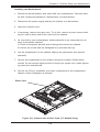
Expansion Card Setup
SC815 chassis include I/O slots for add-on cards and expansion cards. "C" models
(like SC815TQ-700CV) include one full width slot. SC815 "U" model chassis include
two full-height/full length expansion slots and one low-profile expansion slot. Other
models (non-Universal IO) include one full-height/full length expansion slot and
one low-profile slot.
Note: You must use a riser card to install expansion cards to any SC815 chassis.
Riser cards are sold separately.
For the latest compatibility and performance information visit our website at:
SC815-560C
http://www.supermicro.com.
C815-560C
I/O Panel
Figure 5-9: SC815 Chassis Rear
with One Full Height/Full Length I/O slot
SC815-560
I/O Panel
Lever
Figure 5-10: SC815 Chassis Rear
with One Full Height/Full Length I/O slot
and One Low Profile I/O slot
5-10
I/O Panel
Lever
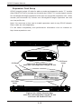
Chapter 5: Chassis Setup and Maintenance
Riser Card
Figure 5-11: Chassis with a Riser Card ("U" Models Only)
Installing an Expansion Card
1. Confirm that you have the correct riser card for your chassis model and the
add-on card includes a standard bracket.
2. Remove the chassis cover.
3. Install the riser card by sliding card into the appropriate slot in the motherboard. For more information, see the riser card installation instructions.
4. Choose the I/O panel in which to place the add-on card.
5. In that slot, open the I/O panel lever and slide the I/O panel sideways.
6. From inside the chassis, remove the I/O panel.
7. Slide the add-on card into the riser card and attach the add-on card bracket
in place of the I/O panel.
8. Secure the add-on card by closing the I/O panel lever.
9. Connect cables to the add-on card as necessary.
5-11
SC815 Chassis Manual
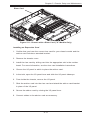
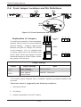
5-7 Installing the Air Shroud
Optional Flap
Figure 5-11: Air Shroud
Front
(Fan Side)
Air shrouds concentrate airflow to maximize fan efficiency. The SC815 chassis air
shroud does not require screws to set up.
Figure 5-12: Air Shroud with the Optional Flap Removed
5-12
Chapter 5: Chassis Setup and Maintenance
Installing the Air Shroud
1. Remove the chassis cover.
2. If your motherboard uses between 9 and 16 DIMMS, skip this step. If your
motherboard uses 8 DIMMS, you must remove the optional flap. To do so:
a. With the fan side facing you, hold the air shroud with your left hand on the
main shroud component and right hand on the optional flap.
b. Gently twist with your right hand by lifting the fan side and lowering the
other end of the optional flap.
3. Place the air shroud in your chassis with the fan side touching the edge of
the fans.
4. Replace the chassis cover.
Checking the Air Flow in the Chassis
1. Make sure there are no objects to obstruct airflow in and out of the chassis. In addition, if you are using a front bezel, make sure the bezel's filter is
replaced periodically.
2. Do not operate the chassis without drive carriers in the drive bays. Use only
recommended chassis parts.
3. Make sure no wires or foreign objects obstruct air flow through the chassis.
Pull all excess cabling out of the airflow path or use shorter cables.
4. The control panel LEDs inform you of system status. See “Chapter 3: System
Interface” for details on the LEDs and the control panel buttons.
5-13
SC815 Chassis Manual
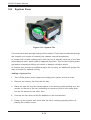
5-8 System Fans
Figure 5-13: System Fan
Four heavy duty fans provide cooling for the chassis. These fans circulate air through
the chassis as a means of lowering the chassis internal temperature.
In models with counter-rotating fans, each fan unit is actually made up of two fans
joined back-to-back, which rotate in opposite directions. This counter-rotating action
generates exceptional airflow and works to dampen vibration levels.
In chassis that provide an additional open fan housing, an additional system fan
may be added for optimal cooling.
Adding a System Fan
1. Turn off the power to the system and unplug the system from the outlet.
2. Remove the dummy fan from the fan tray.
3. Place the new fan into the vacant space in the housing while making sure the
arrows on the top of the fan (indicating air direction) point in the same direction as the arrows on the other fans.
4. Connect the fan wires to the fan headers on the serverboard.
5. Power up the system and check that the fan is working properly before replacing the chassis cover.
5-14
Chapter 5: Chassis Setup and Maintenance
Figure 5-14: Chassis Fans
(Note additional fan options)
The SC815 chassis includes four pre-installed fans. One or two extra slots are
available so that. additional fans may be added.
Replacing a System Fan
1. If necessary, open the chassis while the power is running to determine which
fan has failed. Never run the server for an extended period of time with the
chassis open.
2. Turn off the power to the system and unplug the AC power cord from the
outlet.
3. Remove the failed fan's wiring from the serverboard.
4. Lift the failed fan from the chassis and pull it completely out from the
serverboard.
5. Place the new fan into the vacant space in the housing while making sure the
arrows on the top of the fan (indicating air direction) point in the same direction as the arrows on the other fans.
6. Reconnect the fan wires to the exact same chassis fan headers as the previous fan.
7. Reconnect the AC power cord, power up the system and check that the fan is
working properly before replacing the chassis cover.
5-15
SC815 Chassis Manual
5-9 Power Supply
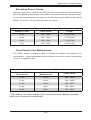
Depending on your chassis model the SC815 Chassis has a 450, 560, 650, 700
710 or 720 Watt power supply. This power supply is auto-switching capable. The
450, 560, 650, 700 and 720 Watt power supplies automatically sense and operate
at a 100V to 240V input voltage. The 710 DC power supply operates at -36DC to
-75DC. An amber light will be illuminated on the power supply when the power is
off. An illuminated green light indicates that the power supply is operating.
Power Supply Failure
If the power supply unit fails, the system will shut down and you will need to replace
the unit. Replacement units can be ordered directly from Supermicro (see contact
information in the Preface). As there is only one power supply unit in the SC815
Chassis, power must be completely removed from the server before removing and
replacing the power supply unit for whatever reason.
5-16
Chapter 5: Chassis Setup and Maintenance
Release Tab
Figure 5-15: Removing the Power Supply
Replacing the Power Supply
1. Power down the server and unplug the power cord. If your chassis includes
a redundant power supply (at least two power modules), you can leave the
server running and remove only one power supply.
2. Push the release tab (on the back of the power supply) as illustrated.
3. Pull the power supply out using the handle provided.
4. Replace the failed power module with the same model.
5. Push the new power supply module into the power bay until you hear a click.
6. Plug the AC power cord back into the module and power up the server.
5-17
SC815 Chassis Manual
5-10 Routing the I2C Cables
It is necessary to correctly route the I2C cables to avoid interference due to noise on
the I2C lines. Using tie wraps, secure the I2C cables to the large black power switching cable to keep it close to the power supply and away from the motherboard.
5-18
Chapter 6: Rack Installation
Chapter 6
Rack Installation
6-1 Overview
This chapter provides a quick setup checklist to get your chassis up and running.
Following these steps in the order given should enable you to have the system
operational within a minimum amount of time.
6-2 Unpacking the System
You should inspect the box the chassis was shipped in and note if it was damaged
in any way. If the chassis itself shows damage you should file a damage claim
with the carrier who delivered it.
Decide on a suitable location for the rack unit that will hold your chassis. It should
be situated in a clean, dust-free area that is well ventilated. Avoid areas where
heat, electrical noise and electromagnetic fields are generated. You will also need
it placed near a grounded power outlet. Be sure to read the Rack and Server
Precautions in the next section.
6-3 Preparing for Setup
The box your chassis was shipped in should include two sets of rail assemblies,
two rail mounting brackets and the mounting screws you will need to install the
system into the rack. Please read this section in its entirety before you begin the
installation procedure outlined in the sections that follow.
Choosing a Setup Location
•Leave enough clearance in front of the rack to enable you to open the front
door completely (~25 inches).
•Leave approximately 30 inches of clearance in the back of the rack to allow for
sufficient airflow and ease in servicing.
•This product is for installation only in a Restricted Access Location (dedicated
equipment rooms, service closets and the like).
6-1
SC815 Chassis Manual
!
Warnings and Precautions!
!
Rack Precautions
•Ensure that the leveling jacks on the bottom of the rack are fully extended to
the floor with the full weight of the rack resting on them.
•In single rack installation, stabilizers should be attached to the rack.
•In multiple rack installations, the racks should be coupled together.
•Always make sure the rack is stable before extending a component from the
rack.
•You should extend only one component at a time - extending two or more simultaneously may cause the rack to become unstable.
General Server Precautions
•Review the electrical and general safety precautions that came with the components you are adding to your chassis.
•Determine the placement of each component in the rack before you install the
rails.
•Install the heaviest server components on the bottom of the rack first, and then
work up.
•Use a regulating uninterruptable power supply (UPS) to protect the server from
power surges, voltage spikes and to keep your system operating in case of a
power failure.
•Allow the hot plug hard drives and power supply modules to cool before touching them.
•Always keep the rack's front door and all panels and components on the servers
closed when not servicing to maintain proper cooling.
6-2
Chapter 6: Rack Installation
Rack Mounting Considerations
Ambient Operating Temperature
If installed in a closed or multi-unit rack assembly, the ambient operating temperature of the rack environment may be greater than the ambient temperature of the
room. Therefore, consideration should be given to installing the equipment in an
environment compatible with the manufacturer’s maximum rated ambient temperature (Tmra).
Reduced Airflow
Equipment should be mounted into a rack so that the amount of airflow required
for safe operation is not compromised.
Mechanical Loading
Equipment should be mounted into a rack so that a hazardous condition does not
arise due to uneven mechanical loading.
Circuit Overloading
Consideration should be given to the connection of the equipment to the power
supply circuitry and the effect that any possible overloading of circuits might have
on overcurrent protection and power supply wiring. Appropriate consideration of
equipment nameplate ratings should be used when addressing this concern.
Reliable Ground
A reliable ground must be maintained at all times. To ensure this, the rack itself
should be grounded. Particular attention should be given to power supply connections other than the direct connections to the branch circuit (i.e. the use of power
strips, etc.).
6-3
SC815 Chassis Manual
6-4 Rack Mounting Instructions
This section provides information on installing the SC815 chassis into a rack unit.
There are a variety of rack units on the market, which may mean the assembly
procedure will differ slightly. You should also refer to the installation instructions that
came with the rack unit you are using.
NOTE: This rail will fit a rack between 26" and 33.5" deep.
Identifying the Sections of the Rack Rails
The chassis package includes two rack rail assemblies in the rack mounting kit.
Each assembly consists of two sections: an inner rail that secures directly to the
chassis, and an outer rail that secures directly to the rack itself.
Outer Rails
Rail Extension
(Inner Rail is pre-installed
on the chassis)
Figure 6-1: Identifying the Sections of the Rack Rails
(right side rail shown)
6-4
Chapter 6: Rack Installation
1
2
3
Figure 6-2: Identifying the Sections of the Rack Rails
(right side rail shown)
Inner Rail Extension
The SC815 chassis includes a set of inner rails which are in two sections: inner rails
and inner rail extensions. The inner rails are pre-attached and do not interfere with
normal use of the cha`sis if you decide not to use a server rack. Attach the inner
rail extension to stabilize the chassis within the rack.
Installing the Inner Rails
1. Place the inner rail extensions on the side of the chassis aligning the hooks
of the chassis with the inner rail extension holes. Make sure the inner rail
extension faces "outward" just like the pre-attached inner rail.
2. Slide the extension toward the front of the chassis.
3. Secure the chassis with 2 screws as illustrated.
4. Repeat steps 1-3 for the other inner rail extension.
6-5
SC815 Chassis Manual
Secure to the
Front of the Rack
Attach the Two Sections of
the Outer Rail Together
Secure to the
Rear of the Rack
Figure 6-3: Assembling the Outer Rails
Installing the Outer Rails to the Rack
1. Attach the longer section of the outer rail to the outside of the shorter section
of the outer rail. You must align the pins with the slides. Both ends of the
outer rail must face the same direction in order to be secured to the rack.
2. Adjust both sections of the outer rail to the proper length so that the rail fits
snugly within the rack.
3. Secure the longer section of the outer rail to the of the rack with two M5
screws and the shorter section to the rear side of the rack with two M5
screws.
4. Repeat steps 1-4 for the remaining outer rail.
6-6
Chapter 6: Rack Installation
3
3
2
SCALE 0.380
Figure 6-4: Installing the Outer Rails to the Server Rack
6-7
SC815 Chassis Manual
C
B
A
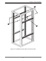
Figure 6-5: Installing the Rack Rails
Installing the Chassis into a Rack
1. Confirm that chassis includes the inner rails (A) and rail extensions (B). Also,
confirm that the outer rails (C) are installed on the rack.
2. Line chassis rails (A and B) with the front of the rack rails (C).
3. Slide the chassis rails into the rack rails, keeping the pressure even on both
sides (you may have to depress the locking tabs when inserting). When the
server has been pushed completely into the rack, you should hear the locking
tabs "click" into the locked position.
4. (Optional) Insert and tighten the thumbscrews that hold the front of the server
to the rack.
6-8
Chapter 6: Rack Installation
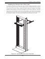
Installing the Chassis into a Telco rack
To install the chassis into a Telco type rack, use two L-shaped brackets on either
side of the chassis (four total). First, determine how far follow the server will extend
out the front of the rack. Larger chassis should be positioned to balance the weight
between front and back. If a bezel is included on your server, remove it. Then attach the two front brackets to each side of the chassis, then the two rear brackets
positioned with just enough space to accommodate the width of the telco rack. Finish
by sliding the chassis into the rack and tightening the brackets to the rack.
Figure 6-6: Installing the Server into a Telco Rack
6-9
SC815 Chassis Manual
Notes
6-10
Appendix A: Chassis Cables
Appendix A
Chassis Cables
A-1 Overview
This appendix lists supported cables for your chassis system. It only includes the
most commonly used components and configurations. For more compatible cables,
refer to the manufacturer of the motherboard you are using and our Web site at
www.supermicro.com.
A-2 Cables Included with SC815TQ (SAS/SATA)
SC815TQ-710
Part #
Type
Length
Description
CBL-0157L
Round ribbon cable
9"
8 pin to 8 pin ribbon cable for
SGPIO.
CBL-0087
Round ribbon cable
20"
16 pin to 16 pin ribbon cable for
control panel
CBL-0139L
Braid ribbon cable
50 cm
IDE 80-wire cable for DVD ROM
CBL-0180L-01
Cable
6'
Cable set
various
Regional power cord
SATA Set of 70/59/48/38cm round
cables
SC815TQ-700
Part #
Type
Length
Description
CBL-0157L
Round ribbon cable
9"
8 pin to 8 pin ribbon cable for
SGPIO.
CBL-0087
Round ribbon
cable
20"
16 pin to 16 pin ribbon cable for
control panel
CBL-0139L
Braid ribbon cable
50 cm
IDE 80-wire cable for DVD ROM
CBL-0180L-01
Cable
SATA set
6'
various
A-1
Regional power cord
SATA set of 70/59/48/38cm
Round Cables
SC815 Chassis Manual
SC815TQ-R650
Part #
Type
Length
CBL-0157L
Round ribbon cable
9"
8 pin to 8 pin ribbon cable for
SGPIO.
CBL-0087
Round ribbon cable
20"
16 pin to 16 pin ribbon cable for
control panel
CBL-0139L
IDE 80-wire cable for DVD-ROM
Braid ribbon cable
50 cm
-
Cable
6'
CBL-0180L-01
SATA set
various
Description
Regional power cord
SATA Set of 70/59/48/38cm
round cables
SC815TQ-560
Part #
Type
Length
Description
CBL-0157L
Round ribbon cable
9"
8 pin to 8 pin ribbon cable for
SGPIO.
CBL-0087
Round ribbon cable
20"
16 pin to 16 pin ribbon cable for
control panel
CBL-0139L
IDE 80-wire cable for DVD-ROM
Braid ribbon cable
60 cm
-
Cable
6'
CBL-0180L-01
SATA set
Various
A-2
Regional power cord
SATA set of 70/59/48/38cm round
cables
Appendix A: Chassis Cables
A-3 Cables Included with SC815S Chassis (SCSI)
SC815S-700
Part #
Type
CBL-033L-U320
Round ribbon cable
9"
ULTRA 320 cable
CBL-0087
Round ribbon cable
20"
16 pin to 16 pin ribbon cable for
control panel
CBL-0139L
Braid ribbon cable
50 cm
IDE 80-wire cable for DVD-ROM
Cable
6'
-
Description
Regional power cord
SC815S-R650
Part #
Type
Length
CBL-033L-U320
Round ribbon cable
9"
ULTRA 320 cable
CBL-0087
Round ribbon cable
20"
16 pin to 16 pin ribbon cable for
control panel
CBL-0139L
Braid ribbon cable
50 cm
Cable
6'
-
Description
IDE 80-wire cable for DVDROM
Regional power cords
SC815S-560
Part #
Type
Length
CBL-033L-U320
Round ribbon cable
9"
ULTRA 320 cable
CBL-0087
Round ribbon cable
20"
16 pin to 16 pin ribbon cable for
control panel
CBL-0139L
Braid ribbon cable
60 cm
Cable
6'
-
A-3
Description
IDE 80-wire cable for DVD
ROM
Regional power cord
SC815 Chassis Manual
A-4 Compatible Cables
These cables are compatible with the SC815 chassis.
Alternate SAS/SATA Cables
Some compatible motherboards have different connectors. If your motherboard
has only one SAS connector that the SAS/SATA cables must share, use one of the
following cables. These cables must be purchased separately.
Cable Name: SAS Cable
Quantity: 1
Part #: CBL-0175L
Alt. Name: "Big Four"
Description: This cable has one SFF-8484 (32 pin) connector on one end and 4
SAS connectors (7 pins each) at the other. This cable connects from the Host
(motherboard or other controller) to the backplane SAS hard drive port.
Cable Name: SAS Cable
Quantity: 1
Part #: CBL-0116
Alt. Name: iPass or "Small Four"
Description: This cable has one ipass (SFF-8087/mini-sas) connector (36 pins) at
one end and 4 SAS connectors on one end. This cable connects from the Host
(motherboard or other controller) to the backplane SAS hard drive port.
A-4
Appendix A: Chassis Cables
Extending Power Cables
Although Super Micro chassis are designed with to be efficient and cost-effective,
some compatible motherboards have power connectors located in different areas.
To use these motherboards you may have to extend the power cables to the mother
boards. To do this, use the following chart as a guide.
Power Cable Extenders
Number of Pins
Cable Part #
Length
24 pin
CBL - 0042
7.9”(20 CM)
20 pin
CBL - 0059
7.9”(20 CM)
8 pin
CBL - 0062
7.9”(20 CM)
4 pin
CBL - 0060
7.9”(20 CM)
Front Panel to the Motherboard
The SC815 chassis includes a cable to connect the chassis front panel to the
motherboard. If your motherboard uses a different connector, use the following list
to find a compatible cable.
Front Panel to Motherboard Cable (Ribbon Cable)
Number of Pins
(Front Panel)
Number of Pins
(Motherboard)
Cable Part #
16 pin
16 pin
CBL - 0049
16 pin
20 pin
CBL - 0048
20 pin
20 pin
CBL - 0047
16 pin
Split*
CBL - 0068
20 pin
Split*
CBL - 0067
* Split cables: Use these cables if your motherboard has different pin definitions than a Supmicro motherboard.
A-5
SC815 Chassis Manual
A-5 Chassis Screws
The accessory box includes all the screws needed to setup your chassis. This section lists and describes the most common screws used. Your
chassis may not require all the parts listed.
M/B
HARD DRIVE
Flat head
6-32 x 5 mm
[0.197]
Pan head
6-32 x 5 mm
[0.197]
DVD-ROM, CD-ROM, and FLOPPY DRIVE
Pan head
6-32 x 5 mm
[0.197]
Flat head
6-32 x 5 mm
[0.197]
Round head
M3 x 5 mm
[0.197]
Round head
M2.6 x 5 mm
[0.197]
RAIL
Flat head
M4 x 4 mm
[0.157]
Round head
M4 x 4 mm
[0.157]
Flat head
M5 x 12 mm[0.472]
Washer for M5
M/B STANDOFFS
M/B standoff
6-32 to 6-32
M/B (CPU)
standoff
M5 to 6-32
Thumb screw
6-32 x 5 mm
[0.197]
A-6
1/U M/B standoff
6-32 x 5 mm
[0.197]
Appendix B: Power Supply Specifications
Appendix B
SC815 Power Supply Specifications
This appendix lists power supply specifications for your chassis system.
Power Supply Specifications
720W
MFR
Part #
PWS-721P-1R
710W/
PDB
700W/PDB
650W/
PDB
(Redundant)
560W
560W
(C Models)
PWS-711
-1R
PWS702A-IR
PWS-651
-1R
PWS-561
-1H20
PWS-561
-1H
Rated
AC Voltage
100-240
V, 50-60
Hz, 4-9
Amp
100 240V
50-60Hz
24-11
Amp
100 - 240V
50 - 60Hz
10-4 Amp
100 240V
50 - 60Hz
8 - 4 Amp
100 240V
50 - 60Hz
8.5 - 4
Amp
100 240V
50 - 60Hz
8.5 - 4
Amp
+5V
standby
3 Amp
4 Amp
4 Amp
3 Amp
3 Amp
3 Amp
DC
Output
3 Amp
at +5V
standby
59 Amp at
+12V
59 Amp
57 Amp
54 Amp
43.6 Amp
43.6 Amp
+12V
+5V
30 Amp
24 Amp
30 Amp
25 Amp
25 Amp
25 Amp
+3.3V
24 Amp
21 Amp
24 Amp
12 Amp
21 Amp
21 Amp
-12V
0.6 Amp
0.6 Amp
0.6 Amp
0.5 Amp
0.6 Amp
0.6 Amp
PDB: Power Distribution Board.
B-1
SC815 Chassis Manual
Notes
B-2
Appendix C: SAS-815TQ Backplane Specifications
Appendix C
SAS-815TQ Backplane Specifications
To avoid personal injury and property damage, carefully follow all the safety steps
listed below when accessing your system or handling the components.
C-1 ESD Safety Guidelines
Electrostatic Discharge (ESD) can damage electronic components. To prevent damage to your system, it is important to handle it very carefully. The following measures
are generally sufficient to protect your equipment from ESD.
• Use a grounded wrist strap designed to prevent static discharge.
• Touch a grounded metal object before removing a component from the antistatic
bag.
• Handle the backplane by its edges only; do not touch its components, peripheral
chips, memory modules or gold contacts.
• When handling chips or modules, avoid touching their pins.
• Put the card and peripherals back into their antistatic bags when not in use.
C-2 General Safety Guidelines
• Always disconnect power cables before installing or removing any components
from the computer, including the SAS-815TQ Backplane.
• Disconnect the power cable before installing or removing any cables from the
SAS-815TQ Backplane.
• Make sure that the SAS-815TQ Backplane is securely and properly installed
on the motherboard to prevent damage to the system due to power shortage.
C-3 An Important Note to Users
• All images and layouts shown in this user's guide are based upon the latest
PCB Revision available at the time of publishing. The card you have received
may or may not look exactly the same as the graphics shown in this manual.
C-1
SC815 Chassis Manual
C-4 Introduction to the SAS-815TQ Backplane
The SAS-815TQ backplane has been designed to utilize the most up-to-date technology available, providing your system with reliable, high-quality performance.
This manual reflects SAS-815TQ Revision 1.00, the most current release available
at the time of publication. Always refer to the Supermicro Web site at www.supermicro.com for the latest updates, compatible parts and supported configurations.
C-2
Appendix C: SAS-815TQ Backplane Specifications
Jumper Settings and Pin Definitions
C-4 Front Connectors and Jumpers
1
GND
GND
SAS815TQ
REV 1.00
+5V
JP47
UPGRADE
R144
+12V
JTAG
JP46
S UPER
JP10
16
13
R
JP29
JP29:9071 RST
#2
J7
+5V
+12V
J8
#3
14
J9
12
JP18
15
JP18:BUZZER RESET
JP40
JP33
JP34
JP42
JP51
M15
MH2
M46
M9
D3
SIDEBAND
+5V
+12V
#1
J10
J6
J5
#0
JP26
I2 C
JP44
ACT IN
ACT0
12
ACT1 ACT2 ACT3
17
Figure C-1: Front Connectors and Jumpers
Front Connectors
#1. Power Connectors (4-pin) JP10
#2. CD-ROM/Floppy Drive Power J9 and J10
#3. JTAG JP47
#4. Upgrade Pin JP46
#5. MG9071 Chip
#6. Sideband JP51
#7. I2C Connector JP44
#8. ACT_IN JP26
#9. SAS Port #0 J5
#10. SAS Port #1 J6
#11. SAS Port #2 J7
#12. SAS Port #3 J8
SAS Ports
GND
GND
R
SAS815TQ
JTAG
REV 1.00
UPGRADE
R144
+12V
JP46
S UPER
JP10
JP29
JP29:9071 RST
JP18
JP18:BUZZER RESET
JP40
JP33
JP34
JP42
JP51
M15
MH2
M46
M9
D3
+5V
JP47
SIDEBAND
#2
J7
+5V
#3
+12V
+5V
+12V
J8
12
1
J9
J10
#1
J6
10
1
111
Figure C-2: SAS Ports
C-3
19
#0
JP44
J5
JP26
2
I C
ACT IN
ACT0
ACT1 ACT2 ACT3
18
SC815 Chassis Manual
C-5 Front Connector and Pin Definitions
#1. Backplane Main Power Connectors
The 4-pin connectors, designated JP10 provide
power to the backplane. See the table on the
right for pin definitions.
Backplane
Main Power
4-Pin Connector
Pin#
1
2 and 3
4
#2. CD-ROM/Floppy 4-Pin Connectors
The 4-pin connectors, designated J9 and J10,
provide power to the CD-ROM and floppy
drives. See the table on the right for pin definitions.
Pin#
#4. MG9071 Chip
The MG9071 is an enclosure management
chip that supports the SES-2 controller and
SES-2 protocols.
C-4
Ground
+5V
Definition
1
4
The JTAG connector, designated JP47, and
the Upgrade connector, designated JP46,
are diagnostic purposes. These connectors
should be used by a certified and experienced
technician.
+12V
CD-ROM/
FDD Power
4-Pin Connector
2 and 3
#3., #4. JTAG Connector and Upgrade Connector
Definition
+5V
Ground
+12V
Appendix C: SAS-815TQ Backplane Specifications
#6. Sideband Headers
Sideband Headers
The sideband headers are designated JP51.
For SES-2 to work properly, you must connect
an 8-pin sideband cable. See the table to the
right for pin definitions.
Pin # Definition
Pin # Definition
2
Backplane
Addressing
(SB5)
1
Controller
ID (SB6)
4
Reset (SB4)
3
GND (SB2)
6
GND (SB3)
5
SDA (SB1)
8
Backplane
ID (SB7)
7
SCL (SB0)
10
No Connection
9
No Connection
#7. I2C Connectors
I2C Connector
Pin Definitions
The I C Connectors, designated JP44, are
used to monitor HDD activity and status. See
the table on the right for pin definitions.
2
#8. Activity LED Header
Pin#
Definition
1
Data
2
Ground
3
Clock
4
No Connection
SAS Activity LED Header
Pin Definitions
The activity LED header, designated JP26,
is used to indicate the activity status of each
Pin # Definition
SAS drive. For the Activity LED Header to work
properly, connect using a 10-pin LED cable.
1
ACT IN#0
6
ACT IN#4
2
ACT IN#1
7
ACT IN#5
3
ACT IN#2
8
ACT IN#6
4
ACT IN#3
9
ACT IN#7
5
Ground
10
Empty
#9., #12. SAS Ports
The SAS ports are used to connect the SAS
drive cables. The four ports are designated
#0 - #4. Each port is also compatible with
SATA drives.
C-5
Pin # Definition
SC815 Chassis Manual
C-6 Front Jumper Locations and Pin Definitions
JP29
GND
GND
SAS815TQ
UPGRADE
R144
+12V
JTAG
REV 1.00
JP46
S UPER
JP10
R
JP29
JP18
JP29:9071 RST
JP18
JP18:BUZZER RESET
JP40
JP33
JP34
JP42
JP51
M15
MH2
M46
M9
D3
+5V
JP47
SIDEBAND
#2
J7
+5V
+12V
+5V
+12V
J8
#3
J9
#1
J10
J6
#0
J5
JP26
I2 C
JP44
ACT IN
ACT0
ACT1 ACT2 ACT3
JP40
JP29:9071 RST
JP18
JP18:BUZZER RESET
D3
+5V
JP33
JP34
JP33
JP34
#1
J6
JP42
JP42
JP51
M15
MH2
M46
M9
SIDEBAND
JP50
+12V
J10
JP40
#0
JP44
J5
JP26
I2 C
ACT IN
ACT0
ACT1 ACT2 ACT3
Figure C-3: Front Connectors and Jumpers
Explanation of Jumpers
To modify the operation of the backplane,
jumpers can be used to choose between
optional settings. Jumpers create shorts
between two pins to change the function
of the connector. Pin 1 is identified with
a square solder pad on the printed circuit
board. Note: On two pin jumpers, "Closed"
means the jumper is on and "Open" means
the jumper is off the pins.
Connector
Pins
3
2
1
3
2
1
Jumper
Setting
Jumper Settings
Jumper
Jumper Settings
Note
JP18
Open: Enabled
Closed: Disabled
Buzzer reset*
JP29
Open: Default
Closed: Reset
MG9071 Chip reset
*The buzzer sound indicates that a condition requiring immediate attention has
occurred.
The buzzer alarm is triggered by the following conditions:
1. Hard drive failure
2. Fan failure
3. System temperature over 45º Celsius.
C-6
Appendix C: SAS-815TQ Backplane Specifications
I2C and SGPIO Modes and Jumper Settings
This backplane can utilize I2C or SGPIO. I2C is the default mode and can be used
without making changes to your jumpers. The following information details which
jumpers must be configured to use SGPIO mode or restore your backplane to I2C
mode.
I2C Setting (Default)
Jumper
Jumper Setting
Note
JP33
2-3
Controller ID
JP34
1-2:ID#0
Backplane ID
JP40
Open
I2C Reset SD OUT
JP42
2-3
Backplane ID SDIN
JP50
Closed
I2C Reset
SGPIO Setting
Jumper
Jumper Setting
Note
JP33
1-2
Controller ID
JP34
1-2:ID#0
Backplane ID
JP40
Closed
I2C Reset SD OUT
JP42
1-2
Backplane ID SDIN
JP50
Open
I2C Reset
Front LED Indicators
GND
GND
R
SAS815TQ
JTAG
REV 1.00
UPGRADE
R144
+12V
JP46
S UPER
JP10
JP29
JP29:9071 RST
JP18
JP18:BUZZER RESET
JP33
JP34
JP40
JP42
JP51
M15
MH2
M46
M9
D3
+5V
JP47
SIDEBAND
#2
J7
+5V
#3
+12V
+5V
+12V
J8
J9
J10
#1
J6
#0
JP44
J5
JP26
2
I C
ACT IN
ACT0
R144
JP29
JP29:9071 RST
JP18
JP18:BUZZER RESET
JP33
JP34
ACT1 ACT2 ACT3
JP40
JP42
JP51
D3
SIDEBAND
+5V
+12V
#1
J10
J6
Overheat
or Drive
Failure LED
#0
JP44
Front Pane LEDs
D3
State
On
Specification
Overheat or drive failure
C-7
JP26
I2 C
ACT0
Figure C-4: Front LED Indicators
LED
J5
ACT1 ACT2
SC815 Chassis Manual
C-7 Rear Connectors and LED Indicators
D14
D7
J4
SAS
#2
SAS
SAS
#2
#1
Figure C-5: Rear Connectors and LED Indicators
Rear SAS/SATA Connectors
Rear
Connector
Connector
Number
SAS Drive
Number
SAS #0
J1
SAS/SATA HDD #0
SAS #1
J2
SAS/SATA HDD #1
SAS #2
J3
SAS/SATA HDD #2
SAS #3
J4
SAS/SATA HDD #3
Rear LED Indicators
Rear
Connector
Hard Drive Activity
Failure LED
SAS #0
D12
D5
SAS #1
D13
D6
SAS #2
D14
D7
SAS #3
D15
D8
C-8
D15
D8
D8
#1
D15
J3
SAS
D7
D13
D6
D14
#0
D6
SAS
#0
J2
SAS
D13
D12
D5
D5
J1
D12
52619H4M
MM
28R
SAS
#3
SAS
#3
Appendix D: SCA-813S Backplane Specifications
Appendix D
SCA-813S Backplane Specifications
To avoid personal injury and property damage, carefully follow all the safety steps
listed below when accessing your system or handling the components.
D-1 ESD Safety Guidelines
Electrostatic Discharge (ESD) can damage electronic components. To prevent damage to your system, it is important to handle it very carefully. The following measures
are generally sufficient to protect your equipment from ESD.
•Use a grounded wrist strap designed to prevent static discharge.
•Touch a grounded metal object before removing a component from the antistatic
bag.
•Handle the backplane by its edges only; do not touch its components, peripheral
chips, memory modules or gold contacts.
•When handling chips or modules, avoid touching their pins.
•Put the card and peripherals back into their antistatic bags when not in use.
D-2 General Safety Guidelines
•Always disconnect power cables before installing or removing any components
from the computer, including the SCA-813S backplane.
•Disconnect the power cable before installing or removing any cables from the
SCA-813S backplane.
•Make sure that the SCA-813S backplane is securely and properly installed on
the motherboard to prevent damage to the system due to power shortage.
D-1
SC815 Chassis Manual
D-3 An Important Note to Users
•All images and layouts shown in this user's guide are based upon the latest PCB
Revision available at the time of publishing. The card you have received may or
may not look exactly the same as the graphics shown in this manual.
D-4 Introduction to the SCA-813S Backplane
The SCA-813S backplane has been designed to utilize the most up-to-date technology available, providing your system with reliable, high-quality performance.
This manual reflects SCA-813S Revision 1.00, the most current release available at
the time of publication. Always refer to the Supermicro Web site at www.supermicro.
com for the latest updates, compatible parts and supported configurations.
D-2
Appendix D: SCA-813S Backplane Specifications
Jumper Settings and Pin Definitions
D-5 Front Connectors and Jumpers
1
12
13
13
Figure D-1: Front Connectors and Jumpers
Front Connectors
#1. Backplane Main (4-Pin) PWR: JP10
#2. GEM 318 Chip
#3. CD-ROM/Floppy Drive (4-Pin) PWR Connector: J1 and J2
#4. SCSI Channel: LVD1
D-3
14
SC815 Chassis Manual
D-6 Front Connector and Pin Definitions
#1. Backplane Main Power Connectors
Backplane
Main Power
4-Pin Connector
The 4-pin connector, designated JP10, provide
power to the backplane. See the table on the
right for pin definitions.
Pin# Definition
1
+12V
2 and 3
Ground
4
#2. GEM Chip (SAF-TE: SCSI Accessed
Fault-Tolerant Enclosures)
The GEM chip allows the system to monitor
the status of the disk drives and provides disk
drive information to the user through the LED
indicators and buzzers.
This function is only available when a RAID
controller with a Raid set is present and
enabled.
#3. CD-ROM/Floppy 4-Pin Connectors
The 4-pin connectors, designated J1 and J2,
provide power to the CD-ROM and floppy
drives. See the table on the right for pin
definitions.
+5V
SAF-TE LED Indicators
LED # Location
Description
D4
Front
Overheat or Drive Failure
(red light, flashing, buzzer
on)
D5
Rear
SCA#0 Fail LED
(red light, flashing, buzzer
on)
D6
Rear
SCA#1 Fail LED
(red light, flashing, buzzer
on)
D16
Rear
SCA#2 Fail LED
(red light, flashing, buzzer
on)
D18
Rear
SCA#3 Fail LED
(red light, flashing, buzzer
on)
CD-ROM/
FDD Power
4-Pin Connector
Pin# Definition
1
2 and 3
4
D-4
+5V
Ground
+12V
Appendix D: SCA-813S Backplane Specifications
#4. Ultra 320 SCSI Connector (LVD1)
The Ultra 320 SCSI connector connects
the backplane to the server motherboard.
D-5
Ultra320 SCSI Drive Connector
Pin Definitions (J28)
Pin# Definition
Pin #
Definition
1
+DB (12)
35
-DB (12)
2
+DB (13)
36
-DB (13)
3
+DB (14)
37
-DB (14)
4
+DB (15)
38
-DB (15)
5
+DB (P1)
39
-DB (P1)
6
+DB (0)
40
-DB (0)
7
+DB (1)
41
-DB (1)
8
+DB (2)
42
-DB (2)
9
+DB (3)
43
-DB (3)
10
+DB (4)
44
-DB (4)
11
+DB (5)
45
-DB (5)
12
+DB (6)
46
-DB (6)
13
+DB (7)
47
-DB (7)
14
+DB (P)
48
-DB (P)
15
Ground
49
Ground
16
DIFFSENS
50
Ground
17
TERMPWR
51
TERMPWR
18
TERMPWR
52
TERMPWR
19
Reserved
53
Reserved
20
Ground
54
Ground
21
+ATN
55
-ATN
22
Ground
56
Ground
23
+BSY
57
-BSY
24
+ACK
58
-ACK
25
+RST
59
-RST
26
+MSG
60
-MSG
27
+SEL
61
-SEL
28
+C/D
62
-C/D
29
+REQ
63
-REQ
30
+I/O
64
-I/O
31
+DB (8)
65
-DB (8)
32
+DB (9)
66
-DB (9)
33
+DB (10)
67
-DB (10)
34
+DB (11)
68
-DB (11)
SC815 Chassis Manual
D-7 Front Jumper Locations and Pin Definitions
JP17
Figure D-2: Front Jumper
Explanation of Jumpers
Connector
Pins
To modify the operation of
the backplane, jumpers can
be used to choose between
optional settings. Jumpers
create shorts between two
pins to change the function
of the connector. Pin 1
is identified with a square
3
2
1
3
2
1
Jumper
Setting
Jumper Settings
Jumper
JP17
Jumper Settings
Closed: Enabled
Open: Disabled
Note
Buzzer enable*
*The buzzer sound indicates that a condition requiring immediate attention has
occurred.
The buzzer alarm is triggered by the following conditions:
1. Hard drive failure
2. Fan failure
3. System temperature over 45º Celsius.
D-6
Appendix D: SCA-813S Backplane Specifications
Front LED Indicators
D4
Backplane LED
LED
D4
State
On
Specification
Overheat/Drive Failure LED Indicator
(Red light: flashing, Buzzer: On)
D-7
SC815 Chassis Manual
D-8 Rear Connectors and LED Indicators
D12
D5
SCA
#1
D13
D6
D14
D16
SCA
#3
D17
D18
SCA
#4
SCA
#2
Figure D-4: Rear Connectors and LED Indicatosr
Rear SCA Connectors
Rear
Connector
Connector
Number
SCA Drive
Number
SCA #1
#0
SCA HDD #0
SCA #3
#1
SCA HDD #1
SCA #4
#2
SCA HDD #2
SCA #2
#3
SCA HDD #3
Rear LED Indicators
Connector
Number
Hard Drive Activity
Failure LED
SCA #1
#0
D12
D5
SCA #3
#1
D13
D6
SCA #4
#2
D14
D16
SCA #2
#3
D17
D18
Rear LED
D-8
Appendix D: SCA-813S Backplane Specifications
D-8 SCSI (Super) GEM Installation Instructions for the
Windows Operating System
The following instructions describe how to install the SCSI GEM driver for the Windows OS systems. This driver is not necessary for other operating systems. If you
have two SCA backplanes, you will need to install the driver twice.
The driver is located on the Supermicro motherboard driver CD is available for download from our FTP site: ftp://ftp.supermicro.com/driver/SCSI_Backplanes/Qlogic/
Use ONE of the following Windows installation procedures to install the drivers to
your system.
Windows Driver Installation Procedure A
1. Right click My Computer and select Properties.
2. Select the Hardware tab and click Device Manager.
3. Open Other Devices or the other location of GEM318.
4. Right click on this device and select Properties.
5. Select the Driver tab and select Update Driver.
6. Click Next twice, uncheck both the Floppy disk drive and CD-ROM drive
options.
7. Select Specify a location, and click Next.
8. Click on Browse and select the D drive, or other location for the Supermicro
Setup CD.
9. Select the Qlogic folder and click Open.
10. System will automatically detect the GEM318 chip and install the drive from
this point on.
Windows Driver Installation Procedure B
Installation Procedure B
1. Right click the My Computer icon on your desktop and select Properties.
D-9
SC815 Chassis Manual
2. Select the Hardware tab and select Device Manager to bring up the list of
system devices.
3. You may see one or two yellow question marks (?) that read QLogic GEM354
or GEM318 SCSI Processor Device. Right click on these, and select
uninstall. If both devices have question marks, uninstall both.
4. Select the Action tab and select Scan for Hardware Changes. The Hardware Wizard program should start up. Click Next.
5. At the first prompt, select Display a list of known device drivers for the
device so that I can choose a specific driver and click Next.
6. Select Other Devices and click Next.
7. Select Have Disk, and specify the floppy drive location in the options box.
Then click Next
8. Select Enclosure Services Device and click Next.
9. Ignore the warning prompt by clicking Yes.
D-10
Appendix D: SCA-813S Backplane Specifications
Notes
D-11
SC815 Chassis Manual
Disclaimer (cont.)
The products sold by Supermicro are not intended for and will not be used in life support systems, medical equipment, nuclear facilities or systems, aircraft, aircraft devices,
aircraft/emergency communication devices or other critical systems whose failure to perform be reasonably expected to result in significant injury or loss of life or catastrophic
property damage. Accordingly, Supermicro disclaims any and all liability, and should
buyer use or sell such products for use in such ultra-hazardous applications, it does so
entirely at its own risk. Furthermore, buyer agrees to fully indemnify, defend and hold
Supermicro harmless for and against any and all claims, demands, actions, litigation,
and proceedings of any kind arising out of or related to such ultra-hazardous use or
sale.
D-12