1
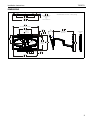
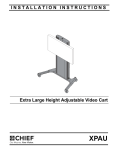
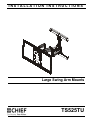
INSTALLATION INSTRUCTIONS
Instrucciones de instalación
Installationsanleitung
Instruções de Instalação
Istruzioni di installazione
Installatie-instructies
Instructions d´installation
Large Swing Arm Mounts
Spanish Product Description
German Product Description
Portuguese Product Description
Italian Product Description
Dutch Product Description
French Product Description
TS525TU
TS525TU
Installation Instructions
DISCLAIMER
Milestone AV Technologies and its affiliated corporations and
subsidiaries (collectively "Milestone"), intend to make this
manual accurate and complete. However, Milestone makes no
claim that the information contained herein covers all details,
conditions or variations, nor does it provide for every possible
contingency in connection with the installation or use of this
product. The information contained in this document is subject
to change without notice or obligation of any kind. Milestone
makes no representation of warranty, expressed or implied,
regarding the information contained herein. Milestone assumes
no responsibility for accuracy, completeness or sufficiency of
the information contained in this document.
Chief® is a registered trademark of Milestone AV Technologies.
All rights reserved.
WARNING: The wall to which the mount is being attached
may have a maximum drywall thickness of 5/8" (1.6cm) when
installing to wood studs or hollow concrete block. If installing
to poured concrete, the wall CANNOT have ANY drywall
covering!
WARNING: Exceeding the weight capacity can result in
serious personal injury or damage to equipment! It is the
installer’s responsibility to make sure the combined weight of
all components attached does not exceed 125 lbs (56.7 kg).
Use with products heavier than the maximum weight
indicated may result in collapse of the mount and its
accessories causing possible injury.
IMPORTANT ! : The TS525TU mount is designed to be
IMPORTANT SAFETY INSTRUCTIONS!
mounted to an 8" concrete, 8"x8"x16" concrete block, brick or
2" x 4" wood studs (16" on center).
--SAVE THESE INSTRUCTIONS!-WARNING: A WARNING alerts you to the possibility of
serious injury or death if you do not follow the instructions.
CAUTION: A CAUTION alerts you to the possibility of
damage or destruction of equipment if you do not follow the
corresponding instructions.
WARNING: Use this mounting system only for its intended
use as described in these instructions. Do not use
attachments not recommended by the manufacturer.
WARNING: Never operate this mounting system if it is
damaged. Return the mounting system to a service center for
examination and repair.
WARNING: Do not use this product outdoors.
WARNING: Failure to read, thoroughly understand, and
follow all instructions can result in serious personal injury,
damage to equipment, or voiding of factory warranty! It is the
installer’s responsibility to make sure all components are
properly assembled and installed using the instructions
provided.
WARNING: Failure to provide adequate structural strength
for this component can result in serious personal injury or
damage to equipment! It is the installer’s responsibility to
make sure the structure to which this component is attached
can support five times the combined weight of all equipment.
Reinforce the structure as required before installing the
component.
2
Installation Instructions
TS525TU
DIMENSIONS
39.1
1.5
DISTANCE FROM WALL
WITH INTERFACE
[35.6]
1.4
WITHOUT INTERFACE
550.28
21.664
821.19
32.330
MAX. WIDTH
MAXIMUM WEIGHT CAPACITY = 125 lbs. (56.7 kg)
800
31.496
MAX. HORIZONTAL PATTERN
406.40
16.000
15
MAX
TILT
17.46
.688
7.00" [177.8]
LEFT/RIGHT
ADJUSTMENT
12.50
.492
651.9
25.67
MAX EXTENSION
FROM WALL
COLLAPSED
VIEW
235.64
9.277
SCREEN
CENTER
100 X 100
200 X 200
PATTERNS
INCLUDED
63.50
2.500
400
15.748
MAX.
VERTICAL
PATTERN
473.08
18.625
526.4
20.73
8.33
.328
749.30
29.500
3
TS525TU
Installation Instructions
LEGEND
4
Tighten Fastener
Pencil Mark
Apretar elemento de fijación
Marcar con lápiz
Befestigungsteil festziehen
Stiftmarkierung
Apertar fixador
Marcar com lápis
Serrare il fissaggio
Segno a matita
Bevestiging vastdraaien
Potloodmerkteken
Serrez les fixations
Marquage au crayon
Loosen Fastener
Drill Hole
Aflojar elemento de fijación
Perforar
Befestigungsteil lösen
Bohrloch
Desapertar fixador
Fazer furo
Allentare il fissaggio
Praticare un foro
Bevestiging losdraaien
Gat boren
Desserrez les fixations
Percez un trou
Phillips Screwdriver
Adjust
Destornillador Phillips
Ajustar
Kreuzschlitzschraubendreher
Einstellen
Chave de fendas Phillips
Ajustar
Cacciavite a stella
Regolare
Kruiskopschroevendraaier
Afstellen
Tournevis à pointe cruciforme
Ajuster
Open-Ended Wrench
Remove
Llave de boca
Quitar
Gabelschlüssel
Entfernen
Chave de bocas
Remover
Chiave a punte aperte
Rimuovere
Steeksleutel
Verwijderen
Clé à fourche
Retirez
By Hand
Optional
A mano
Opcional
Von Hand
Optional
Com a mão
Opcional
A mano
Opzionale
Met de hand
Optie
À la main
En option
Hex-Head Wrench
Security Wrench
Llave de cabeza hexagonal
Llave de seguridad
Sechskantschlüssel
Sicherheitsschlüssel
Chave de cabeça sextavada
Chave de segurança
Chiave esagonale
Chiave di sicurezza
Zeskantsleutel
Veiligheidssleutel
Clé à tête hexagonale
Clé de sécurité
Installation Instructions
TS525TU
TOOLS REQUIRED FOR INSTALLATION
concrete only
13/64" (5.1mm) - wood studs
3/8" (10mm) - concrete
1/2" (12.7mm)
#2
PARTS
"A"
A1 (6)
M4x10mm
A2 (6)
M4x16mm
A3 (6)
M4x25mm
N (1)
[wall rail]
M (1)
[main assembly]
B1 (6)
M5x10mm
"B"
B2 (6)
M5x16mm
B3 (6)
M5x25mm
P (1)
[right upright]
"C"
C1 (6)
M6x10mm
"D"
"E"
D1 (4)
M8x10mm
D2 (4)
M8x20mm
C3 (6)
M6x25mm
D3 (4)
M8x30mm
T (2)
S (1)
[wall cover]
R (1) [bottom interface support]
[top interface support]
E3 (1)
E2 (6)
E4 (6)
E1 (6) .75x.344x.5 M5 [univ.washer]
.75x.323x.25
hardware
bag
washer
bag
C2 (6)
M6x16mm
Q (1)
[left upright]
G (4)
F (4)
H (4)
5/16 x 2 1/2" [concrete anchor] [install. washer]
J (4)
M5
K (4)
M4
V (1)
X (2)
U (1)
W (8)
5/16-18"
[knob assembly] #10-24 x 1 1/4" #10-24 x 1/2"
Z (1)
L (4)
Y (1)
[shoulder washer] [latch spacer] 1/8"
CC (2)
[long adhesive]
AA (1)
1/4"
BB (1)
3/16"
DD (4)
[short adhesive]
5
TS525TU
Installation Instructions
Assembly And Installation
Install Wall Plate to Wall - Wood Studs
WARNING: Failure to provide adequate structural strength
for this component can result in serious personal injury or
damage to equipment! It is the installer’s responsibility to
make sure the structure to which this component is attached
can support five times the combined weight of all equipment.
Reinforce the structure as required before installing the
component. The wall to which the mount is being attached
may have a maximum drywall thickness of 5/8" (1.6cm).
1.
Determine mounting location. Use stud finder to locate 2" x
4" wood studs.
2.
Measure 9 5/16" above desired center line and draw a
horizontal line. (See Figure 1)
4
(F) x 2
6
(H) x 2
NOTE: Hold mount up to wall at desired mounting location if
unsure about where the center line will be. The center
line of the mount will coincide with the center line of the
display. (See Figure 1)
(N)
Figure 2
7.
Slide main assembly (M) onto wall rail (N). (See Figure 3)
IMPORTANT ! : Use a level to make sure wall rail (N) is
level when mounted to the wall!
3.
Drill two 13/64" holes at center of wood studs along the line
drawn in the Step 2. (See Figure 1)
3
(N)
x2
(M)
7
16"
9 5/16
Figure 3
center line
(M)
8.
Center main assembly (M) over two studs.
9.
Drill two 13/64" holes in center of wood studs at lower
mounting holes. (See Figure 4)
10. Loosely install two 5/16 x 2 1/2" flange head lag screws (F).
(See Figure 4)
11. Place two installation spacers (H) over two flange head lag
screws (F). (See Figure 4)
Figure 1
4.
Loosely attach wall rail (N) to wall using two 5/16- 2 1/2"
flange head lag screws (F). (See Figure 2)
5.
Place two installation spacers (H) over two 5/16 x 2 1/2"
flange head lag screws (F). (See Figure 2)
6.
Tighten two screws (F) to secure upper wall rail (N) to wall.
(See Figure 2)
6
12. Tighten two screws to secure main assembly (M) to wall.
(See Figure 4)
Installation Instructions
TS525TU
Install Wall Plate to Wall - Hollow Concrete
Block or Poured Concrete (Important!- Read
warnings below for drywall restrictions!)
WARNING: Failure to provide adequate structural strength
10
for this component can result in serious personal injury or
damage to equipment! It is the installer’s responsibility to
make sure the structure to which this component is attached
can support five times the combined weight of all equipment.
Reinforce the structure as required before installing the
component.
(F) x 2
12
9
x2
WARNING: The wall to which the mount is being attached
11
may have a maximum drywall thickness of 5/8" (1.6cm) if
installing to hollow concrete block. If installing to poured
concrete, the wall CANNOT have ANY drywall covering!
(H) x 2
WARNING: INSTALLING THE TS525TU INTO
Figure 4
UNDERRATED OR DAMAGED CONCRETE CAN LEAD TO
SERIOUS INJURY OR DAMAGE TO PRODUCT! When
installing into concrete, only install the TS525TU into
concrete at least 8" in depth or into 8"x8"x16" concrete
blocks! Never install the TS525TU into cracked, chipped or
flaking concrete.
WARNING: DO NOT REMOVE SPACER AS SHOWN
BELOW PRIOR TO INSTALLING THE LOWER TWO LAG
SCREWS OR THE MOUNT WILL FALL OFF THE WALL
WHEN THE SPACER IS REMOVED!
13. Loosen two flat head cap screws on upper carriage rail in
order to loosen white spacer. (See Figure 5)
1.
Determine mounting location.
2.
Measure 9 5/16" above desired center line and draw a
horizontal line. (See Figure 6)
14. Remove white spacer from mount. (See Figure 5)
NOTE: Hold mount up to wall at desired mounting location if
15. Tighten flat head cap screws. (See Figure 5)
(N)
13
unsure about where the center line will be. The center
line of the mount will coincide with the center line of the
display. (See Figure 6)
15
IMPORTANT ! : Use a level to make sure wall rail (N) is
level when mounted to the wall!
3.
(M)
Drill two 3/8" holes 16" apart and along the line drawn in the
Step 2. (See Figure 6)
3
x2
16”
9 5/16”
14
Figure 5
16. Proceed to Install Interface Bracket to Display section on
page 9.
center line
(M)
Figure 6
7
TS525TU
Installation Instructions
4.
Install two concrete anchors (G) into two drilled holes. (See
Figure 7)
5.
Loosely attach wall rail (N) to wall by installing two 5/16- 2
1/2 flange head lag screws (F) into concrete anchors (G).
(See Figure 7)
center of wall rail
11
IMPORTANT ! : Use a level to make sure wall rail (N) is
level when mounted to the wall!
6.
Place two installation spacers (H) over two 5/16 x 2 1/2"
flange head lag screws (F). (See Figure 7)
7.
Tighten two screws to secure upper wall rail (N) to wall.
(See Figure 7)
(N)
8
(M)
5
(F) x 2
7
4
(G) x 2
13
10
x2
12
x2
(G) x 2 (with main assembly removed)
(N)
6
(H) x 2
Figure 8
Figure 7
8.
Slide main assembly (M) onto wall rail (N). (See Figure 8)
9.
Center main assembly (M) over wall rail (N). (See Figure 8)
14. Slide main assembly (M) back onto wall rail (N). (See Figure
9)
(N)
10. Mark two holes at lower mounting holes. (See Figure 8)
11. Slide main assembly (M) off wall rail (N). (See Figure 8)
12. Drill two 3/8" holes at marked locations. (See Figure 8)
13. Install two concrete anchors (G) into drilled holes. (See
Figure 8)
(M)
14
Figure 9
8
Installation Instructions
TS525TU
15. Loosely install two 5/16 x 2 1/2" flange head lag screws (F)
through lower wall rail on main assembly and into concrete
anchors. (See Figure 10)
16. Place two installation spacers (H) over two flange head lag
screws (F). (See Figure 10)
17. Tighten two screws (F) to secure main assembly (M) to wall.
(See Figure 10)
15
(F) x 2
17
16
(H) x 2
Figure 10
WARNING: DO NOT REMOVE SPACER AS SHOWN
BELOW PRIOR TO INSTALLING THE LOWER TWO LAG
SCREWS OR THE MOUNT WILL FALL OFF THE WALL
WHEN THE SPACER IS REMOVED!
18. Loosen two flat head cap screws on upper carriage rail in
order to loosen white spacer. (See Figure 11)
19. Remove white spacer from mount. (See Figure 11)
20. Tighten flat head cap screws. (See Figure 11)
(N)
18
20
(M)
19
Figure 11
9
TS525TU
Installation Instructions
Install Interface Bracket to Display
IMPORTANT ! : If the displays hole pattern size is
100mm x100mm, 200mm x 200mm or 100mm x 200mm,
the display can be mounted directly to the faceplate and
the interface bracket DOES NOT need to be installed!
Proceed to Install Display section.
1.
(A-C) x4,x6,x8 or
6
2
(D) x4
(P)
4
Lay display face down on protective surface.
CAUTION: Using screws of improper diameter may
5
damage your display! Proper screws will easily thread into
display mounting holes.
2.
Select screw diameter by examining hardware (A-D) (4mm,
5mm, 6mm or 8mm) and comparing with mounting holes on
display. (See Figure 12)
3.
Select spacers: (See Figure 12)
•
•
If mounting holes are not recessed and both
uprights (P and Q) can lay flat against display,
then no spacers are required.
If mounting holes are recessed, or if protrusions
prevent uprights (P and Q) from laying flat, then
spacers (E1 or E2) must be used.
(Q)
(E4) x4,x6,x8
(not needed with D)
(E1 or E2) x4,x6,x8
(only with recessed holes)
Figure 12
CAUTION: Using screws of improper length may damage
your display! Proper screws will have adequate thread
engagement without contacting bottom of display mounting
holes.
4.
for narrow mounting hole pattern
(Q)
Select screw length: (See Figure 12)
•
(P)
Using your hand, insert SHORTEST length screw
of selected diameter (A1, B1,C1 or D1) through
universal washer (E4), uprights (P or Q), selected
spacer (E1 or E2, if required), into display
mounting hole. Do NOT thread screw into hole at
this time.
NOTE: Universal washers (E4) are not needed if using M8
button head cap screws (D).
•
5.
Proper screw length requires base of screw head
to protrude above flat washer a distance equal to
or greater than the screw diameter. If screw
length is inadequate, select longer screw. Select
shortest screw which will protrude the required
distance.
Place uprights (P and Q) on display, ensuring: (See Figure
13)
•
Center of uprights (P and Q) are as close to the
center of the back of display as possible after
being installed. Center of bracket is indicated by
the diamond-shaped hole.
NOTE: If installing to a display with a narrow hole mounting
pattern, reverse uprights (P and Q) so that the upright
legs do not overlap onto each other. (See Figure 13)
10
legs would otherwise
overlap
Figure 13
6.
Using Phillips screwdriver, carefully install selected screws
through universal washers (E4, if required), uprights (P and
Q), and spacers (E1 or E2, if required), into display. (See
Figure 12)
7.
Tighten all screws. Ensure all applicable display mounting
holes (4, 6, or 8) are used.
TS525TU
Installation Instructions
10. When connecting bottom interface support (S) to uprights,
make sure that it is aligned vertically with top interface
support (R). (See Figure 14)
8
(W) x 4
Installing Display
(R)
Using Interface Bracket
WARNING: Exceeding the weight capacity can result in
10
serious personal injury or damage to equipment! It is the
installer’s responsibility to make sure the combined weight of
all components attached does not exceed 125 lbs (56.7 kg).
Use with products heavier than the maximum weight
indicated may result in collapse of the mount and its
accessories causing possible injury.
WARNING: Display may be very heavy! Ensure display
can be safely lifted and maneuvered as required to install on
wall plate. Failure to take adequate precautions can result in
serious personal injury or damage to equipment!
(S)
9
(W) x 4
1.
Hang interface bracket and display to faceplate by placing
two mounting buttons on top interface support (R) over two
teardrop grooves on top of faceplate. (See Figure 15)
2.
Secure interface bracket and display to faceplate by
installing two 5/16-18" flange nuts (X) onto screws on lower
interface support (S). (See Figure 15)
Figure 14
8.
Connect top interface support (R) to uprights (P and Q)
using four #10-24 x 1/2" button head cap screws (W). (See
Figure 14)
NOTE: If possible install screws diagonally across from each
other in order to provide maximum support in Steps 8
and 9.
9.
Connect bottom interface support (S) to uprights (P and Q)
using four #10-24 x 1/2" button head cap screws (W). (See
Figure 14)
(R)
1
(S)
2
Figure 15
11
(X) x 2
TS525TU
Installation Instructions
Installing Display Without Interface Bracket
(100x100, 200x200 or 100x200)
(200 x 200 shown)
CAUTION: Using screws of improper diameter may
damage your display! Proper screws will easily thread into
display mounting holes.
1.
(K) x 2 with (A)
or
(J) x 2 with (B)
Select screw diameter by examining hardware (A-D) (4mm,
5mm, 6mm or 8mm) and comparing with mounting holes on
display.
4
CAUTION: Using screws of improper length may damage
your display! Proper screws will have adequate thread
engagement without contacting bottom of display mounting
holes.
2.
Select screw length:
•
3.
Using your hand, insert SHORTEST length screw
of selected diameter (A1, B1, C1 or D1) into
display mounting hole. Do NOT thread screw into
hole at this time.
(L) x 2 (with A and B ONLY!)
Install two selected screws (A-D) into upper two holes on
back of display. (See Figure 16)
IMPORTANT ! : If using M4 or M5 screws (A or B),
washer hardware (J, K and L) must be used to ensure
tight fit into the faceplate holes! For M4 screws (A), use
M4 washer (K) and shoulder washer (L). For M5 screws
(B), use M5 washer (J) and shoulder washer (L). (See
Figure 16)
(A-C) x 2
5
or
(D) x 2
Figure 17
Wall Cover Installation
(L) x2 (with A and B ONLY!)
CAUTION: Wall covers are fragile and may be damaged or
(K) x 2 with (A)
or
(J) x 2 with (B)
broken if installed with excessive force! Use caution when
installing and removing wall covers.
1.
Turn wall cover (T) outward to allow outside of covers to
wrap around wall rail. (See Figure 18)
2.
Place wall cover (T) over wall rail. (See Figure 18)
2
3
(A-C) x 2
or
2
1
(D) x 2
Figure 16
4.
Hang display by two screws onto faceplate through either
inner or outer teardrop mounting holes. (200x200 mounting
pattern shown) (See Figure 17)
5.
Secure display to faceplate by installing two selected
screws (A-D) through washer hardware (J,K, and L) for M4
(A) and M5 (B) screws only, lower holes on faceplate and
into lower two holes on display. (See Figure 17)
12
Figure 18
(T) x 2
Installation Instructions
TS525TU
Cable Management
1.
Make all cable connections to display.
2.
Open cable management covers on upper and lower swing
arms. (See Figure 19)
3.
Route cables on top of upper arm. (See Figure 19)
4.
(Optional) Use cable ties (not included) to secure cables to
upper arms by threading ties around cable and through
cable tie holes on arms. (See Figure 19)
5.
Close upper cable management cover. (See Figure 19)
6.
Route cables under lower portion of swing arm. (See Figure
19)
7.
(Optional) Use cable ties (not included) to secure cables to
lower arms by threading ties around cable and through
cable tie holes on arms. (See Figure 19)
8.
remove and replace
with (V)
2
5
4
3 (Y)
6
remove and replace
with (U)
Close lower cable management cover. (See Figure 19)
cable management
covers
Figure 20
2
3
5.
Remove 1/2" knob assembly installed on center support.
(See Figure 20)
6.
Replace 1/2" knob assembly with 1" knob assembly (U).
(See Figure 20)
Height Adjustment
4 cable ties
(not included)
8
1.
Extend swing arms in order to gain access to the center
support.
2.
Adjust height adjustment wrench to raise or lower mount to
desired height. Turn counter-clockwise to raise mount and
clockwise to lower mount. (See Figure 21)
2
cable (typical)
raise
lower
Figure 19
Creating Space (Optional)
In order to create more space between display and mount,
spacers may be added.
1.
Extend swing arms in order to gain access to the center
support.
2.
Remove flat hex-head screw holding latch to center
support. (See Figure 20)
3.
Place latch spacer (Y) behind latch and line with holes on
center support. (See Figure 20)
4.
Install #10-24 x 1 1/4" flat hex-head screw (V) through latch
and latch spacer (Y) and into holes on center support. (See
Figure 20)
Figure 21
13
TS525TU
Installation Instructions
Leveling Friction Adjustment
Lateral Shift Adjustment
1.
1.
Remove wall rail covers (N) to expose lateral shift
adjustment screws on wall rails.
2.
Loosen four lateral shift adjustment screws. (See Figure 24)
3.
Loosen two lower lag screws securing lower rail to the wall.
(See Figure 24)
4.
Slide mount laterally to desired mounting position. (See
Figure 24)
5.
Tighten two lower lag screws. (See Figure 24)
6.
Tighten four lateral shift adjustment screws. (See Figure 24)
7.
Reinstall wall rail covers (N).
Adjust leveling adjustment screw on back of faceplate to
increase or decrease leveling friction. (See Figure 22)
6
2
leveling adjustment
screw
4
Figure 22
Tilt Friction Adjustment
1.
Tilt display forward enough to expose screws on the side of
tilting mechanism. (See Figure 23)
2.
Adjust tilt friction adjustment screw to increase or decrease
tilt friction. (See Figure 23)
4
(swing arms not shown
for display purposes)
(side view)
tilt friction adjustment screws
3
5
Figure 24
Figure 23
14
Installation Instructions
Arm Tension Adjustment
1.
Use 1/4" hex key (AA) to adjust arm tension at any of the
four arm tension adjustment points. (See Figure 25)
not adjustable
with hex key
TS525TU
Install Interface Bracket Adhesive Covers
(Optional)
If the interface bracket was required to install display to mount,
adhesive covers may be used to cover the holes on the
interface bracket in order to improve the appearance.
1.
Use two long adhesive strips (CC) to cover vertical uprights.
(See Figure 27)
2.
Use four short adhesive strips (DD) to cover horizontal
upright supports. (See Figure 27)
NOTE: These strips may be cut as desired in order to fit around
screws.
2
(DD) x 4
1
(CC) x 2
arm tension
adjustment points
Figure 25
2.
Use 9/16" wrench to adjust arm tension directly behind
faceplate. (See Figure 26)
Figure 27
arm tension
adjustment points
Figure 26
15
TS525TU
Installation Instructions
USA/International
Europe
Chief Manufacturing, a products division
of Milestone AV Technologies
8805-002008 REV 06
2011 Milestone AV Technologies, a
Duchossois Group Company
www.chiefmfg.com
10/11
Asia Pacific
A
P
F
A
P
F
A
8401 Eagle Creek Parkway, Savage, MN 55378
800.582.6480 / 952.894.6280
877.894.6918 / 952.894.6918
Fellenoord 130 5611 ZB EINDHOVEN, The Netherlands
+31 (0)40 2668620
+31 (0)40 2668615
Office No. 1 on 12/F, Shatin Galleria
18-24 Shan Mei Street
Fotan, Shatin, Hong Kong
P 852 2145 4099
F 852 2145 4477