Transcript
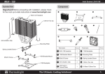
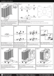
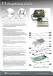
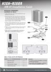
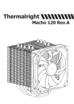
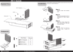
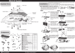
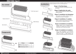
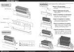
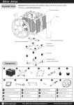
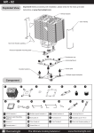
XP-90
Installation Guide
1A
K8 installation for XP-90
1D
1B
1. Remove stock RM by unscrew both Philip screws and drip
a couple drops of nail polish remover on the sides of RM to
unglue it from the motherboard, this way RM can be easily
removed without damage PCB and components.
2. Put a thin, even layer of thermal grease on both CPU IHS
and HSF base.
3. Place the included K8 Adapting RM around CPU and use
enclosed M3 15mm screws 8A/B to secure the adapting
RM into stock backplate.
4. Hook the retention hooks 5/6 A into K8 Adapting RM holes
7 A/B, use them as leverage point and gently push HSF
down into RM. Hold the HSF down.
5. Use a small flat screw driver, and hook 5/6 B into RM holes
7 C/D. Slightly rotate the HSF for optimal contact with
CPU IHS.
6. Hook fan wire clip 2 C/D into holes 4A/B, do the same with
fan clip 3C/D to 4C/D. (pic. 2)
7. Put enclosed white rubber strips on the side of HSF fins to
damper the fan vibration. (pic. 3)
8. Place the 80/90/92 mm fan of your choice on top rubber
strips over the Heatsink fins. Hook fan wire clips 2A/B to
lower fan casing screw holes 1A/B, 3 A/B to lower fan
casing screw holes 1C/D.
3A
2A
3C
2C
3B
3D
2B
2D
4B
4D
5A
6B
5B
7B
8B
8A
7A
7D
7C
4B
2D
blue rubber
strips
(pic. 2)
XP-90 parts list
Parts List
Quantity
HSF Body with 2 mounting clips
1
White Rubber vibration damper strips
2
80 mm fan wire clips
2
90 / 92 mm fan wire clips
2
Thermal paste in syringe
1
K8 Adaptive RM
1
M3 15mm screws
2
(pic. 3)
Top View
Side View
www.thermalright.com