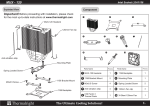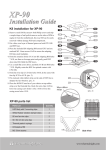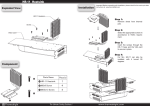
1
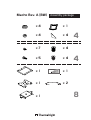
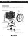
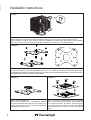
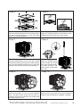
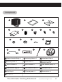
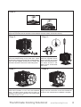
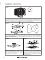
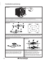
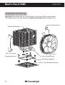
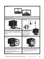
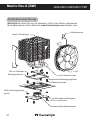
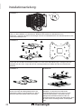
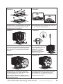
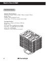
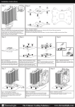
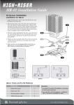
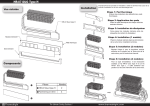
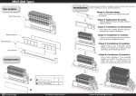
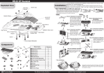
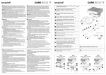
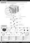
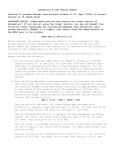
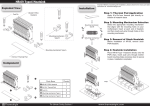
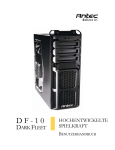
Thermalright
Macho Rev. A (BW)
Macho Rev. A (BW)
Assembly package
×4
× 1
×4
× 4
×7
× 4
×5
× 4
× 1
× 1
× 1
Chill Factor
2g
4
4
× 1
× 2
8
Macho Rev.A (BW)
Intel 775/1155/1156/1366
Exploded View
Important! Before proceeding with installation, please check for the most
up-to-date instructions at www.thermalright.com
Fan Clip
Macho Heatsink Body
M3 L6 Screw
Anchoring Mount
TY-147
Anti-Vibration Pads
Mounting Plate
Screw Nut
Intel Washer
(small)
Metal Back Plate
M3 L10 Screw
Backplate cap
1
Component
1
2
4
3
5
10
9
13
6
14
7
12
11
Chill Factor
8
15
16
2g
1
Macho Heatsink Body ×1
2
Anchoring Mount ×1
3
Metal Back Plate ×1
4
Mounting Plate ×1
5
Screw Nut ×4
6
LGA2011 Type B
Screw Pillars x4
7
M3 L10 Screw ×5
8
M3 L6 Screw ×7
9
Intel Washer (small) ×4
10 AMD Washer (big) ×4
11 Anti-Vibration Pad ×4
12 Backplate cap ×1
13 Fan Clip ×2
14 Thermal paste ×1
15 Screw driver ×1
16 TY-147 ×1
The Ultimate Cooling Solutions!
www.thermalright.com
2
Installation Instructions:
Step 1:
Step 1 : Part Installation
Take out Macho cooler from the paper box.Remove the TY-147 from the cooler by pulling the Fan
Clips upwards in order to give room for ease of installation. And leave the Fan Clips on the Heatsink
Body. Do not remove them. Apply Anti-Vibration Padding to 4 corners on the Heatsink Body.
Step 2:
1366
775
1156
1155
Step 2 : Backplate Installation
Choose the platform (775/1155/1156/1366) you are in use. Make four M3L10 Screw Pillars go through
the Metal Back Plate from bottom towards top.And then place the Metal Back Plate on the table. Put the
four Washers (for Intel) around the Screw Pillars.
Step 3:
Step 3 : 775 backplate cap
Note: When installing on a 775 platform, please
first insert the Back Plate Cap into the opening on
the Back plate, make sure you have the Cap facing
downwards. (Only for 775).
3
Step 4:
Step 4 : Place the motherboard on top of the Back
Plate. See the four Screw Pillars go through the
four holes around the processor socket.Cap the
four Screw Pillars with the four Screw Nuts.Make
sure the side with a washer is facing the Back
Plate.
Step 5:
Step 6:
Chill
or
Fact
2g
Chill
Step 5 :
Place the Anchoring Mount on the Screw Nuts.
Use the four M3L6 Screws to fix the Anchoring
Mount on to the Screw Pillars.
Step 7:
Step 7: Mounting Plate Installation
Place the Heatsink Body on top of the CPU. Make
the Mounting Plate go through the Heatsink Body.
Then use the supplied Screw Driver to fasten the
two M3L6 Screws to Secure the Mounting Plate.
Step 9:
Step 9 : Fan Installation
Place the included TY-147 onto the Heatsink
Body. And then secure it with the Fan Clips, by
pulling the Fan Clips to place the four ends at the
four holes on the TY-147.
or
Fact
2g
Step 6 : Applying Thermal Paste
Apply the Thermal Paste to the base of the
Heatsink and the surface of the CPU evenly.
Step 8:
Step 8: Easy Access
Pass the supplied Screw
Driver through the central
hole of the Heatsink Body,
for easier access to the
M3L6 Screw underneath
the cooler.
Step 10:
Step 10 : Installation completed
Plug in the fan connector to the CPU PWM Fan
socket on the motherboard. Installation complete.
The Ultimate Cooling Solutions!
www.thermalright.com
4
Macho Rev.A (BW)
Intel 2011
Exploded View
Important! Before proceeding with installation, please check for the most
up-to-date instructions at www.thermalright.com
Fan Clip
Macho Heatsink Body
M3 L6 Screw
Anchoring Mount
Intel Washer
(small)
TY-147
Anti-Vibration Pads
Mounting Plate
LGA2011 Type B Screw Pillars
5
Component
1
2
4
3
5
10
9
13
6
14
7
12
11
Chill Factor
8
15
16
2g
1
Macho Heatsink Body ×1
2
Anchoring Mount ×1
3
Metal Back Plate ×1
4
Mounting Plate ×1
5
Screw Nut ×4
6
LGA2011 Type B
Screw Pillars x4
7
M3 L10 Screw ×5
8
M3 L6 Screw ×7
9
Intel Washer (small) ×4
10 AMD Washer (big) ×4
11 Anti-Vibration Pad ×4
12 Backplate cap ×1
13 Fan Clip ×2
14 Thermal paste ×1
15 Screw driver ×1
16 TY-147 ×1
The Ultimate Cooling Solutions!
www.thermalright.com
6
Installation Instructions:
Step 1:
Step 1 : Part Installation
Take out Macho cooler from the paper box.Remove the TY-147 from the cooler by pulling the Fan
Clips upwards in order to give room for ease of installation. And leave the fan clips on the Heatsink Body.
Do not remove them. Apply Anti-Vibration Padding to 4 corners on the Heatsink Body.
Step 2:
Step 2 : Place the motherboard on top of the Back Plate. See the four Screw Pillars go through the four
holes around the processor socket.Cap the four Screw Pillars with the four Screw Nuts.Make sure the
side with a washer is facing the Back Plate.
Step 3:
Step 3 :
Place the Anchoring Mount on the Screw Nuts. Use the four M3L6 Screws to fix the Anchoring Mount on
to the Screw Pillars.
7
Macho Rev.A (BW)
Step 4:
Chill
or
Fact
2g
Chill
or
Fact
2g
Step 4 : Applying Thermal Paste
Apply the Thermal Paste to the base of the Heatsink and the surface of the CPU evenly.
Step 5:
Step 5: Mounting Plate Installation
Place the Heatsink Body on top of the CPU. Make
the Mounting Plate go through the Heatsink Body.
Then use the supplied Screw Driver to fasten the
two M3L6 Screws to Secure the Mounting Plate.
Step 7:
Step 7 : Fan Installation
Place the included TY-147 onto the Heatsink
Body. And then secure it with the Fan Clips, by
pulling the Fan Clips to place the four ends at the
four holes on the TY-147.
Step 6:
Step 6: Easy Access
Pass the supplied Screw
Driver through the central
hole of the Heatsink Body,
for easier access to the
M3L6 Screw underneath
the cooler.
Step 8:
Step 8 : Installation completed
Plug in the fan connector to the CPU PWM Fan
socket on the motherboard. Installation complete.
The Ultimate Cooling Solutions!
www.thermalright.com
8
Macho Rev.A (BW)
AM2/AM2+/AM3/AM3+/FM1
Exploded View
Important! Before proceeding with installation, please check for the most
up-to-date instructions at www.thermalright.com
Fan Clip
Macho Heatsink Body
M3 L6 Screw
Anchoring Mount
TY-147
Anti-Vibration Pads
Mounting Plate
Screw Nut
AMD Washer
(big)
Metal Back Plate
M3 L10 Screw
Backplate cap
9
Component
1
2
4
3
5
10
9
13
6
14
7
12
11
Chill Factor
8
15
16
2g
1
Macho Heatsink Body ×1
2
Anchoring Mount ×1
3
Metal Back Plate ×1
4
Mounting Plate ×1
5
Screw Nut ×4
6
LGA2011 Type B
Screw Pillars x4
7
M3 L10 Screw ×5
8
M3 L6 Screw ×7
9
Intel Washer (small) ×4
10 AMD Washer (big) ×4
11 Anti-Vibration Pad ×4
12 Backplate cap ×1
13 Fan Clip ×2
14 Thermal paste ×1
15 Screw driver ×1
16 TY-147 ×1
The Ultimate Cooling Solutions!
www.thermalright.com
10
Installation Instructions:
Step 1:
Step 1 : Part Installation
Take out Macho cooler from the paper box. Remove the TY-147 from the cooler by pulling the Fan Clips
upwards in order to give room for ease of installation. And leave the Fan Clips on the Heatsink Body. Do
not remove them. Apply Anti-Vibration Padding to 4 corners on the Heatsink Body.
Step 2:
AMD
Step 2 : Backplate Installation
Choose the platform (AMD) you are in use. Make four M3L10 Screw Pillars go through the Metal Back
Plate from bottom towards top. And then place the Metal Back Plate on the table. Put the four Washers (for
AMD) around the Screw Pillars.
Step 3:
Step 3 :backplate cap
Note: When installing on a 939 platform, please
first insert the Back Plate Cap into the opening
on the Back plate, make sure you have the Cap
facing downwards. (Only for 939).
11
Step 4:
Step 4 : Place the motherboard on top of
the Back Plate. See the four Screw Pillars go
through the four holes around the processor
socket.Cap the four Screw Pillars with the four
Screw Nuts.Make sure the side with a washer is
facing the Back Plate.
Step 5:
Step 6:
Chill
or
Fact
2g
Chill
Step 5 :
Place the Anchoring Mount on the Screw Nuts.
Use the four M3L6 Screws to fix the Anchoring
Mount on to the Screw Pillars.
Step 7:
Step 7: Mounting Plate Installation
Place the Heatsink Body on top of the CPU. Make
the Mounting Plate go through the Heatsink Body.
Then use the supplied Screw Driver to fasten the
two M3L6 Screws to Secure the Mounting Plate.
Step 9:
Step 9 : Fan Installation
Place the included TY-147 onto the Heatsink
Body. And then secure it with the Fan Clips, by
pulling the Fan Clips to place the four ends at the
four holes on the TY-147 .
or
Fact
2g
Step 6 : Applying Thermal Paste
Apply the Thermal Paste to the base of the
Heatsink and the surface of the CPU evenly.
Step 8:
Step 8: Easy Access
Pass the supplied Screw
Driver through the central
hole of the Heatsink Body,
for easier access to the
M3L6 Screw underneath
the cooler.
Step 10:
Step 10 : Installation completed
Plug in the fan connector to the CPU PWM Fan
socket on the motherboard. Installation complete.
The Ultimate Cooling Solutions!
www.thermalright.com
12
Macho Rev.A (BW)
Intel 775/1155/1156/1366
Explosionszeichnung
Wichtig! Bitte prüfen Sie vor der Montage, ob für Ihren Kühler aktualisierte
Montagehinweise auf der Webseite www.themalright.com verfügbar sind.
Lüfterklammer
Macho Kühlkörper
M3 L6 Schraube
Montagerahmen
TY-147
Anti-Vibrationpad
Befestigungsplatte
Rändelschraube
Intel
Unterlegscheibe
(klein)
Multi Plattform Backplate
M3 L10 Schraube
Backplateeinsatz
13
Komponenten
1
2
4
3
5
10
9
13
6
14
7
12
11
Chill Factor
8
15
16
2g
1
Macho Kühlkörper ×1
2
Montagerahmen ×1
3
Multi Plattform Backplate×1
4
Befestigungsplatte ×1
5
Rändelschraube ×4
6
LGA2011 Type B
Adapterschraube x4
7
M3 L10 Schraube ×5
8
M3 L6 Schraube ×7
9
Intel Unterlegscheibe
(klein) ×4
10 (groß) ×4
AMD Unterlegscheibe
11
Anti-Vibrationspad ×4
12
Backplateeinsatz ×1
13 Lüfterklammer ×2
14
Wärmeleitpaste ×1
15
Schraubendreher ×1
16 TY-147 ×1
The Ultimate Cooling Solutions!
www.thermalright.com
14
Installationsanleitung:
Schritt 1:
Nachdem Sie den Macho Kühler aus der Verpackung genommen haben demontieren Sie zunächst den
Lüfter, um die Installation zu vereinfachen. Belassen Sie hierbei die Lüfterklammern am
Kühlkörper - entfernen Sie diese nicht. Bringen Sie die vier selbstklebenden Anti-Vibrationspads an den
Ecken des Kühlkörpers an.
Schritt 2:
1366
775
1156
1155
Achten Sie auf die für die entsprechenden Intel Sockel (775/1155/1156/1366) vorgesehene
Bohrungen in der Multi Plattform Backplate. Führen Sie die vier M3L10 Schrauben jeweils von unten
durch diese Bohrungen und legen dann die Backplate auf den Tisch. Legen Sie die vier Unterlegscheiben
(für Intel) über die hervorstehenden Gewinde.
Schritt 3:
Beachten Sie:
Bei Verwendung einer Intel Sockel 775 Plattform
setzen Sie zuerst den Backplateeinsatz in die
quadratische Öffnung der Backplate ein. Gehen
Sie sicher, dass der Aufsatz nach unten zeigt.
15
Schritt 4:
Platzieren Sie das Mainboard von oben auf die
Backplate, so dass die hervorstehenden
Schraubengewinde durch die Löcher um den
Prozessorsockel gehen. Schrauben Sie die
beiliegenden Rändelschrauben auf die vier
Schraubengewinde. Achten Sie dabei darauf, dass
die Seite mit der Unterlegscheibe zur Backplate
zeigt.
Schritt 5:
Schritt 6:
Chill
or
Fact
2g
Chill
Setzen Sie den Montagerahmen auf die
Rändelschrauben. Verwenden Sie die vier
M3L6 Schrauben, um den Montagerahmen
auf den Rändelschrauben zu befestigen.
Schritt 7:
Platzieren Sie nun den Kühlkörper auf die CPU.
Führen Sie anschließend die Befestigungsplatte
durch den Kühlkörper und benutzen die beiden
M3L6 Schrauben, um die Befestigungsplatte zu
befestigen.
Schritt 9:
Positionieren Sie den mitgelieferten TY-147 auf
die Kühlerseite mit den bereits angebrachten
AntiVibrationspads. Nun sichern Sie den Lüfter
mit den Lüfterklammern, indem Sie
diese über den Lüfterrahmen klappen und die
spitzwinkeligen Ecken in die Montagelöcher des
Lüfters einrasten lassen.
or
Fact
2g
Tr a g e n S i e e i n e h a u c h d ü n n e S c h i c h t
Wärmeleitpaste auf der Oberfläche der CPU und
auf der Unterseite des Kühlers auf.
Schritt 8:
Führen Sie den mitgelieferten
Schraubendreher durch das
Loch in der Mitte des
Kühlkörpers, um leichter
Zugang zu den M3L6
Schrauben unterhalb des
Kühlers zu erhalten.
Schritt 10:
Verbinden Sie den Lüfterstecker mit dem
CPU PWM Lüfteranschluss auf dem Mainboard.
Die Installation ist nun abgeschlossen. Bitte
prüfen Sie die ordnungsgemäße Funktion vor
Inbetriebnahme Ihres PC.
The Ultimate Cooling Solutions!
www.thermalright.com
16
Macho Rev.A (BW)
Intel 2011
Explosionszeichnung
Wichtig! Bitte prüfen Sie vor der Montage, ob für Ihren Kühler aktualisierte
Montagehinweise auf der Webseite www.thermalright.com verfügbar sind.
Macho Kühlkörper
M3 L6 Schraub
Montagerahmen
Lüfterklammer
TY-147
Anti-Vibrationspad
Befestigungsplatte
LGA2011 Type B Adapterschraube
17
Component
1
2
4
3
5
10
9
13
6
14
7
12
11
Chill Factor
8
15
16
2g
1
Macho Kühlkörper ×1
2
Montagerahmen ×1
3
Multi Plattform Backplate×1
4
Befestigungsplatte ×1
5
Rändelschraube ×4
6
LGA2011 Type B
Adapterschraube x4
7
M3 L10 Schraube ×5
8
M3 L6 Schraube ×7
9
Intel Unterlegscheibe
(klein) ×4
10 (groß) ×4
AMD Unterlegscheibe
11
Anti-Vibrationspad ×4
12
Backplateeinsatz ×1
13 Lüfterklammer ×2
14
Wärmeleitpaste ×1
15
Schraubendreher ×1
16 TY-147 ×1
The Ultimate Cooling Solutions!
www.thermalright.com
18
Installationsanleitung:
Schritt 1:
Nachdem Sie den Macho Kühler aus der Verpackung genommen haben demontieren Sie zunächst den
Lüfter, um die Installation zu vereinfachen. Belassen Sie hierbei die Lüfterklammern am
Kühlkörper - entfernen Sie diese nicht. Bringen Sie die vier selbstklebenden Anti-Vibrationspads an den
Ecken des Kühlkörpers an.
Schritt 2:
Schrauben Sie die beiliegenden Rändelschrauben auf die vier Schraubengewinde, die sich um den
Sockel befinden.
Schritt 3:
Setzen Sie den Montagerahmen auf die Rändelschrauben. Verwenden Sie die vier M3L6 Schraubenum
den Montagerahmen auf den Rändelschrauben zu befestigen.
19
Macho Rev.A (BW)
Schritt 4:
Chill
or
Fact
2g
Chill
or
Fact
2g
Tragen Sie eine hauchdünne Schicht Wärmeleitpaste auf der Oberfläche der CPU und auf der
Unterseite des Kühlers auf.
Schritt 5:
Platzieren Sie nun den Kühlkörper auf die CPU.
Führen Sie anschließend die Befestigungsplatte
durch den Kühlkörper und benutzen die
beideM3L6 Schrauben, um die Befestigungsplatte
zbefestigen.
Schritt 7:
Positionieren Sie den mitgelieferten TY-147 auf
die Kühlerseite mit den bereits angebrachten
AntiVibrationspads. Nun sichern Sie den Lüfter
mit den Lüfterklammern, indem Sie
diese über den Lüfterrahmen klappen und die
spitzwinkeligen Ecken in die Montagelöcher des
Lüfters einrasten lassen.
Schritt 6:
Führen Sie den mitgelieferten
Schraubendreher durch das
Loch in der Mitte des
Kühlkörpers, um leichter
Zugang zu den M3L6
Schrauben unterhalb des
Kühlers zu erhalten.
Schritt 8:
Verbinden Sie den Lüfterstecker mit dem
CPU PWM Lüfteranschluss auf dem Mainboard.
Die Installation ist nun abgeschlossen. Bitte
prüfen Sie die ordnungsgemäße Funktion vor
Inbetriebnahme Ihres PC.
The Ultimate Cooling Solutions!
www.thermalright.com
20
Macho Rev.A (BW)
AM2/AM2+/AM3/AM3+/FM1
Explosionszeichnung
Wichtig!Bitte prüfen Sie vor der Montage, ob für Ihren Kühler aktualisierte
Montagehinweise auf der Webseite www.thermalright.comverfügbar sind.
Lüfterklammer
Macho Kühlkörper
M3 L6 Schraube
Montagerahmen
TY-147
Anti-Vibration Pads
Befestigungsplatte
Rändelschraube
AMD Unterlegscheibe
(groß)
Multi Plattform Backplate
M3 L10 Schraube
Backplateeinsatz
21
Component
1
2
4
3
5
10
9
13
6
14
7
12
11
Chill Factor
8
15
16
2g
1
Macho Kühlkörper ×1
2
Montagerahmen ×1
3
Multi Plattform Backplate×1
4
Befestigungsplatte ×1
5
Rändelschraube ×4
6
LGA2011 Type B
Adapterschraube x4
7
M3 L10 Schraube ×5
8
M3 L6 Schraube ×7
9
Intel Unterlegscheibe
(klein) ×4
10 (groß) ×4
AMD Unterlegscheibe
11
Anti-Vibrationspad ×4
12
Backplateeinsatz ×1
13 Lüfterklammer ×2
14
Wärmeleitpaste ×1
15
Schraubendreher ×1
16 TY-147 ×1
The Ultimate Cooling Solutions!
www.thermalright.com
22
Installationsanleitung:
Schritt 1:
Nachdem Sie den Macho Kühler aus der Verpackung genommen haben demontieren Sie zunächst den
Lüfter, um die Installation zu vereinfachen. Belassen Sie hierbei die Lüfterklammern am
Kühlkörper - entfernen Sie diese nicht. Bringen Sie die vier selbstklebenden Anti-Vibrationspads an den
Ecken des Kühlkörpers an.
Schritt 2:
AMD
Achten Sie auf die für den AMD Sockel vorgesehene Bohrungen in der Multi Plattform Backplate.
Führen Sie die vier M3L10 Schrauben jeweils von unten durch diese Bohrungen und legen dann die
Backplate auf den Tisch. Legen Sie die vier Unterlegscheiben (für AMD) über die hervorstehenden
Gewinde.
Schritt 3:
Bei Verwendung einer AMD Sockel 939 Plattform
setzen Sie zuerst den Backplateeinsatz in die
quadratische Öffnung der Backplate ein. Gehen
Sie sicher, dass der Aufsatz nach unten zeigt.
23
Schritt 4:
Platzieren Sie das Mainboard von oben auf die
Backplate, so dass die hervorstehenden
Schraubengewinde durch die Löcher um den
Prozessorsockel gehen. Schrauben Sie die
beiliegenden Rändelschrauben auf die vier
Schraubengewinde. Achten Sie dabei darauf, dass
die Seite mit der Unterlegscheibe zur Backplate
zeigt.
Schritt 5:
Schritt 6:
Chill
or
Fact
2g
Chill
Setzen Sie den Montagerahmen auf die
Rändelschrauben. Verwenden Sie die vier M3L6
Schrauben, um den Montagerahmen auf den
Rändelschrauben zu befestigen.
Schritt 7:
Platzieren Sie nun den Kühlkörper auf die CPU.
Führen Sie anschließend die Befestigungsplatte
durch den Kühlkörper und benutzen die beiden
M3L6 Schrauben, um die Befestigungsplatte zu
befestigen.
Schritt 9:
Positionieren Sie den mitgelieferten TY-147 auf
die Kühlerseite mit den bereits angebrachten
AntiVibrationspads. Nun sichern Sie den Lüfter
mit den Lüfterklammern, indem Sie
diese über den Lüfterrahmen klappen und die
spitzwinkeligen Ecken in die Montagelöcher des
Lüfters einrasten lassen.
or
Fact
2g
Tragen Sie eine hauchdünne Schicht
Wärmeleitpaste auf der Oberfläche der CPU und
auf der Unterseite des Kühlers auf.
Schritt 8:
Führen Sie den mitgelieferten
Schraubendreher durch das
Loch in der Mitte des
Kühlkörpers, um leichter
Zugang zu den M3L6
Schrauben unterhalb des
Kühlers zu erhalten.
Schritt 10:
Verbinden Sie den Lüfterstecker mit dem
CPU PWM Lüfteranschluss auf dem Mainboard.
Die Installation ist nun abgeschlossen. Bitte
prüfen Sie die ordnungsgemäße Funktion vor
Inbetriebnahme Ihres PC.
The Ultimate Cooling Solutions!
www.thermalright.com
24
Macho Rev.A (BW)
Technical Spec
Heatsink Specifications:
Dimension: Length 152mm x Width 136mm x Height 163mm
Weight: 870g
Heatpipe: 6mm heatpipe*6 units
Copper Base: C1100 Pure copper nickel plated
Fan Specification:
Dimension: L160mm x H140mm x W26.5m
Weight: 140g
Fan speed: 900~1300RPM (4-Pin PWM)
Fan noise: 17~21dBA MAX (4-Pin PWM)
Airflow: 56~73CFM MAX
Connector: 4 Pin (PWM Fan connector)
25
45. 1
162.15
102
14 0
40
50
The Ultimate Cooling Solutions!
42
54. 2
www.thermalright.com
26
Macho Rev.A (BW)
Awards
27
The Ultimate Cooling Solutions!
www.thermalright.com
The Ultimate Cooling Solutions!
www.thermalright.com
TEL: +886-2-8663-6630
FAX: +886-2-8663-6645
EMAIL: [email protected]