1
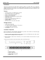
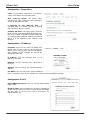
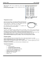
IPower Control 2x6
User Guide
English
LINDY No. 32656
www.lindy.co.uk
© LINDY ELECTRONICS LIMITED & LINDY-ELEKTRONIK GMBH - FIRST EDITION (August 2011)
IPower 2x6
User Guide
Introduction
Thank you for purchasing the LINDY IPower Control 2x6 Switch. This Switch allows you to control the
supply of power for up to 12 devices via a TCP/IP network. The Switch access is password protected
through a web interface connected by serial or SNMP and is powered by two separate 16A phases, each
powering 6 IEC C14 sockets.
Features
•
•
•
•
•
•
•
•
•
•
Switching capacity: max 2300W (10A) per channel
Total switching capacity up to 7360W (32A)
Output: 12 x IEC 320 C14 Sockets
Inputs: 2 x IEC 320 C20 Plugs
Configurable via web browser or included software
Built-in DHCP client
Network Connectivity: Ethernet 10/100 Base-Tx
Firmware updateable via Ethernet
Supports SNMP
Dimensions (W x D x H): 483 x 150 x 43mm
Package Contents
•
•
•
•
•
LINDY IPower Control 2x6
12 x Extension cables IEC 320 C13 – IEC 320 C14
2 x UK power cords – IEC 320 C19
1 x CD containing software & manual
This manual
Installation & Operation
Ensure all equipment is turned off before connecting the any cables. Once all cables are connected, apply
power to the switch then to each device individually.
1.) Connect the power supply cable to the power socket (h) at the rear of IPower 2x6 and a mains socket.
IPower 2x6 now is booting will soon be ready for use
2.) Plug the Ethernet cable into the connector (c) on the front of IPower 2x6 and connect it to your
Ethernet LAN
3.) Connect the client devices to the active outlets at the rear of IPower 2x6 (i)
a)
b)
c)
d)
e)
Power Port LEDs
Power supply LEDs
Ethernet connector (RJ45)
Status LED
Buttons “Select“ and “OK“
IPower 2x6
f)
g)
h)
i)
User Guide
Temperature connector
RS232 connector
2 x Power Socket (IEC C20, max. 16A)
2 x 6 Power Ports (IEC C13, max. 10A)
LED (d) Definition:
•
•
•
•
Solid red LED: Device is not connected to ethernet
Solid orange LED: Device is connected to ethernet, TCP/IP settings are not allocated
Solid green LED: Device is connected to ethernet, TCP/IP settings allocated, device is
ready to use
Status LED blinks alternately red and green: Device is in Bootloader mode
Automatic configuration by DHCP
When you first switch on your IPower 2x6 it will look for a DHCP server and request an available IP
address (for deactivation of that feature see next section).
Please check the IP address allocated to the IPower 2x6 in the DHCP server settings to make sure that
the same address is used at every reboot.
Network configuration by GBL_Conf.exe
For changing the network properties manually, the program GBL_Conf.exe is required. This tool is
available for free on our website www.LINDY.com.
GBL_Conf.exe enables you to install
firmware updates and to reset the IPower
2x6 back to its factory settings. (see
Firmware update section).
Activate bootloader mode of the IPower
2x6 and run GBL_Conf.exe (see
Bootloader mode section). The program
will automatically look for connected
devices and will display their network
configuration. If the displayed IP address
matches the factory settings
(192.168.0.2), there is either no DHCP
server available in the network or no free
IP address could be allocated. Enter a
free IP address and netmask in to the
relevant boxes, then save these changes
by clicking on Program Device → Save
Config.
Restart the IPower 2x6 by switching it off
and on again and the changes will take
effect.
Now click on Search in order to have the new network configuration displayed.
Configuration by Web interface
Go to the web page of IPower 2x6. Enter the IP address into the address line of your internet browser:
http://”IP address of IPower 2x6” and press LOGIN.
To enter the configuration menu, click on “Configuration”.
IPower 2x6
User Guide
Configuration - Power Ports
Label: A name with a maximum of 15 characters
can be entered here for each Power Port.
After power-up switch: The Power Port’s
switching state after a power-on can be defined as
on, off, or remember last state.
If switching on after power-up, wait...: A
switching delay of a Power Port can be defined
with a wait of up to 8191 seconds.
Combine A-B Ports: The Power Ports of Source
Bank A and its equivalent of Bank B (Example A2 B2) can be switch synchronized. Power Ports that
are configured for combined switching are marked
with a C in the Switching menu and the serial
interface.
Configuration - IP Address
Hostname: Enter the host name of IPower 2x6.
IPower 2x6 uses this name to connect with the
DHCP server. Using special signs may destabilize
your network. In this example we named the
Switch EPC-NET-2x6.
IP Address: You can manually enter an IP
address in this field.
Netmask: You can manually enter a Netmask in
this field.
Gateway: You can change the standard gateway
address.
Use DHCP: You can select if the switch should get its TCP/IP settings directly from your DHCP server. If
there is no DHCP server on your network, we recommend deactivating this function.
Configuration IP ACL
Reply ICMP-Ping requests: You can set if the Switch should
reply to pings.
Enable IP Filter: You can activate the IP Access Control List
(IP ACL) of the Switch. If IP ACL is active, DHCP and SNMP
will only work, if all necessary servers and clients are
registered in this list.
IPower 2x6
User Guide
Configuration - HTTP
HTTP Port: You can manually enter the HTTP port number, if
necessary. Numbers range from 1 ... 65534 (standard: 80).
To get access to the switch, you have to enter the port
number behind the IP address: http://192.168.0.2:1720
Require HTTP Password: Password protected access can
be activated here. In this case, a user and an admin
password have to be defined. Passwords have maximum
lengths of 15 characters.
Administrators are authorized to switch all ports and to modify
the settings of the Switch and of all ports. The username of
the admin is “admin”.
Users are authorized to switch all ports but are not allowed to
modify the settings of either the Switch or the ports. The
username of the user is “user”.
If you have forgotten your password, activate the bootloader
mode of the Switch, start GBL-Conf.exe and deactivate the
password request.
All changes need a restart of the firmware to be validated.
Configuration - Messages
Generate Temperature Messages: You can select to have
messages generated when the temperature is beyond the
parameters set.
Max Temperature: Manually select a Max Temperature.
Min Temperature: Manually select a Min Temperature.
Configuration - SNMP - Config
Enable SNMP-get: You can activate “get SNMP” protocol
for the Switch.
Community Public: Allows you to enter the public
community.
Enable SNMP-set: You can activate “set SNMP” protocol
for the Switch.
Community Private: Allows you to enter the private
community.
Download SNMP-MIB: You can download the MIBs of the
Switch.
Configuration - SNMP - Traps
Enable Traps: You can activate SNMP-traps. If enabled, IPower 2x6 will dispatch SNMP-traps to all
receivers listed. Receivers have to be listed as follows: IP address (and, if necessary the HTTP port) e.g.:
HTTP://192.168.0.2:8000
Trap Version: You can choose between SNMP traps standard 1 and 2c. Use SNMP only if your network
supports it.
IPower 2x6
User Guide
Configuration - Syslog
Enable Syslog: You can select to have the syslog enabled
or disabled.
Syslog Server IP: If you enable the syslog you will need to
enter the IP address of the Syslog server.
Syslog Port: If syslog is enabled you will need to enter the
port number that your Syslog server uses to receive syslog
information.
IP Access Control List
The IP Access Control List (IP ACL) acts as an IP filter for your switch. Active hosts and subnets only can
contact the Switch if their IP addresses are stated in this IP ACL.
e.g.: “http://192.168.0.1” or “http://192.168.0.1/24”
If you locked yourself out by mistake, please activate bootloader mode of the Switch and start
Gbl_Conf.exe and deactivate IP ACL.
SNMP
To get detailed status information of IPower 2x6, SNMP can be used. SNMP communicates via UDP (port
161): You can also use SNMP to switch the power ports.
Supported SNMP commands:
- SNMPGET: request status information
- SNMPGETNEXT: request the next status information
- SNMPSET: request change of status
You will need a Network Management System, e.g. HP-Open View, Open NMS, Nagios etc., or the
command line tools of NETSNMP to request information of IPower 2x6 via SNMP.
SNMP Communities
SNMP authenticates the requests from the named communities.
The public community has to be added to SNMP-read-requests and the private community to SNMP write
requests. You can see the SNMP communities like read/write passwords. SNMP v1 and v2 transmit the
communities without encryption. Therefore it is simple to spy out these communities. We recommend you
use a DMZ or IP ACL.
MIBs
All information that can be requested or changed, called “Managed Objects”, are listed in “Management
Information Bases” (MIBs).
There are three MIBs, which can be requested from the IPower 2x6: “system”, “interface” and
“powerports”. “System” and “interface” are standardised MIBs (MIB-II). “Powerports” has been created
especially for IPower 2x6.
Object Identifiers (OID) describes the location of information inside an MIB.
SNMP-Traps
SNMP-Traps are system messages, sent via SNMP-protocol to different clients. On particular events,
IPower 2x6 will dispatch a SNMP-Trap:- Switching of the Power Ports.
Syslog
Syslog messages are simple text messages transmitted to a syslog server using UDP.
Linux OS regularly have a syslog daemon installed, e.g. syslog-ng. For Windows there are some freeware
tools available.
On following events, IPower 2x6 will send a syslog message:
- Booting up
- Activation/deactivation of syslog
- Switching of Power Ports
IPower 2x6
User Guide
Switching via the push buttons
The front of the Switch has two buttons, “select” and
“ok”.
Select: Pushing “select” once make the LED of Power
Port 1 start to blink, which means that it is selected.
Pushing the button again will select the next port.
OK: To change the switching state of the selected
Power Port, press “ok” for two seconds.
You can check the status of the Power Ports by the Colour of the Power Port status LED: Green = Enabled
/ Red = Disabled.
Switching by Web interface
Go to the website of IPower 2x6 and Enter the IP
address into the address line of your internet browser:
http://”IP address of IPower 2x6”/ and press LOGIN
Here you are able to switch the ports directly. You can
check the status of the Power Ports by the colour of the
Power Port status LED: Green = Enabled / Red =
Disabled.
Batchmode
Each Power Port of IPower 2x6 can be switched on or switched off for a selectable delay (1-30 sec. or 130 min.). After the chosen delay the selected port will be switched off or switched on again automatically.
Optionally the device can be accessed by using the pearl script “EPC_Control.pl” through the command
line (e.g. for automatic or time-triggered switching).
Switching via Serial Interface
The Power Ports of Switch can be managed through its
serial interface which only requires a terminal program like
HyperTerminal. This is a program provided under Windows
for free (to be found under Programs → Accessories →
Communication). Connect your PC to your Switch by a 9
pin serial cable (RS232) and plug the device into a power
outlet. Now you can turn on the Switch. The boot process
lasts a few seconds longer than when connected by
Ethernet. You can access the Switch through the terminal
program as soon as the status LED shines green. Choose the COM port that is connected to Switch and
enter the values listed for the serial interface.
If you do not use HyperTerminal, please make sure that the terminal program supports VT100
commands.
When you have connected successfully, the Switch will show
the details to the right.
Press Enter to login.
IPower 2x6
User Guide
Now the Power Ports can be switched on and off using
number keys.
By pressing c you can check the network configuration and by
pressing Esc you can log out.
Temperature sensor
Connect the temperature sensor with the TEMP (f) connector on the
front of the device. When the connector is correctly instered the
recent temperature is displayed in the login window also in the
switching window and can be requested via SNMP.
The temperature sensor can be ordered as an optional extra,
please contact LINDY for more information.
Bootloader mode
To activate the bootloader mode of IPower 2x6 press the buttons “select” and “ok” on the front of the
Switch for three seconds. In bootloader mode it is possible to disable the password protection, to update
the firmware and to restore the default settings by running the program GBL_Conf.exe.
The bootloader mode of IPower 2x6 is indicated by “BOOTLDR” appended to the device name in the
program window of GBL_Conf.exe and by the alternating red and green blinking status led.
When in Bootloader mode you are unable to make changes to the switching state of any port.
To deactivate the bootloader mode press the buttons “select” and “ok” again for three seconds.
Firmware update
In order to update the firmware the program GBL_Conf.exe and the latest firmware are needed.
Activate the bootloader mode of the Switch and run the program GBL_Conf.exe. On the left side of the
program window all Switches that are in the network are listed.
Select the Switch you would like to update, click on Program Device → Firmware Update and select the
location of the new firmware.
To activate the new firmware, you need to deactivate the bootloader mode.
Technical information
•
•
•
•
•
•
Connections:
• 1 x Ethernet (RJ45)
• 1 x Serial Interface (D-SUB, RS232)
• 8 x Power Ports (IEC C13, max. 10A)
• 2 x Power supply inlet (IEC C20, max.16A)
Network connection: 10/100MBit Ethernet
Protocols: TCP/IP, HTTP, SNMP, Syslog
Operating temperatur: 0°C-50°C
Dimensions: 19’’ / 1 rack unit
Weight: 2.3 kg
IPower 2x6
Default settings
In order to restore the default settings, the IPower 2x6 must be
started in bootloader mode. The you will need to run the
GBL_Conf.exe program. When you run Run GBL_Conf.exe,
select the IPower 2x6 device which you would like to restore the
settings on and click on the Program Deviceg → Reset to Fab
default.
Please note that all current settings will be deleted. The default
settings will be loaded when IPower 2x6 is restarted.
User Guide
CE, FCC & WEEE Statements
CE Statement
This device complies with the European Regulations for Electromagnetic Compatibility (EMC) of the European Union and it
is equipped with the CE mark. This unit has to be used with high quality shielded connection cables. Only if such high
quality shielded cables are used can you be sure that the EMC compatibility is not adversely influenced.
FCC Statement
Shielded cables must be used with this equipment to maintain compliance with radio frequency energy emission regulations
and ensure a suitably high levell of immunity to electromagnetic disturbances.
FCC Warning
This equipment has been tested and found to comply with the limits for a Class B Digital device, pursuant to part 15 of the
FCC Rules. These limits are designed to provide reasonable protection against harmful interference in a residential
installation. This equipment generates, uses and can radiate radio frequency energy and if not installed and used in
accordance with the instructions, may cause harmful interference to radio communications. However, there is no guarantee
that interference will not occurr in a particular installation. If this equipment does cause harmful interference to radio or
television reception, which can be determined by turning the equipment off and on, the user is encouraged to try to correct
the interference by one or more of the
e following measures:
Reorient or relocate the receiving antenna
Increase the separation between the equipment and receiver
Connect the equipment into an outlet on a circuit different from that to which the receiver is connected
Consult the dealer or an experienced
perienced technician for help
You are cautioned that changes or modifications not expressly approved by the party responsible for compliance could void
your authority to operate the equipment.
WEEE (Waste of Electrical and Electronic Equipment),
Recycling
ng of Electronic Products
United Kingdom
In 2006 the European Union introduced regulations (WEEE) for the collection and recycling of all waste electrical and
electronic equipment. It is no longer permitted to simply throw away electrical and electronic equipment. Instead, these
products must enter the recycling process.
Each individual EU member state has implemented the WEEE regulations into national law in slightly different ways. Please
follow your national law when you want to dispose of any electrical
electric or electronic products.
More details can be obtained from your national WEEE recycling agency.
Germany / Deutschland
Die Europäische Union hat mit der WEEE Direktive umfassende Regelungen für die Verschrottung und das Recycling von
Elektro- und Elektronikprodukten
onikprodukten geschaffen. Diese wurden von der Bundesregierung im ElektroElektro
und
Elektronikgerätegesetz – ElektroG in deutsches Recht umgesetzt.
Dieses Gesetz verbietet vom 24.März 2006 an das Entsorgen von entsprechenden, auch alten, ElektroElektro und
Elektronikgeräten
geräten über die Hausmülltonne! Diese Geräte
müssen den lokalen Sammelsystemen bzw. örtlichen
Sammelstellen zugeführt werden! Dort werden sie kostenlos entgegen genommen. Die Kosten für den weiteren
Recyclingprozess übernimmt die Gesamtheit der Gerätehersteller.
Gerätehers
France
En 2006, l'union Européenne a introduit la nouvelle réglementation (DEEE)
( EEE) pour le recyclage de tout équipement électrique
et électronique.
Chaque Etat membre de l’ Union Européenne a mis en application la nouvelle réglementation DEEE de manières
légèrement différentes. Veuillez suivre le décret d’application correspondant à l’élimination des déchets électriques ou
électroniques de votre pays.
Italy
Nel 2006 l’unione europea ha introdotto regolamentazioni (WEEE) per la raccolta e il riciclo
rici
di apparecchi elettrici ed
elettronici. Non è più consentito semplicemente gettare queste apparecchiature, devono essere riciclate.
Ogni stato membro dell’ EU ha tramutato le direttive WEEE in leggi statali in varie misure. Fare riferimento alle leggi del
proprio Stato quando si dispone di un apparecchio elettrico o elettronico.
Per ulteriori dettagli fare riferimento alla direttiva WEEE sul riciclaggio del proprio Stato.
No. 32656
www.lindy.com
© LINDY ELECTRONICS
SL
LIMITED & LINDY-ELEKTRONIK GMBH - FIRST EDIT
DITION (Aug 2011)