1
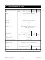
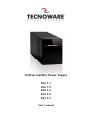
Uninterruptible Power Supply
EXA
EXA
EXA
EXA
EXA
1.1
1.5
2.2
2.6
3.2
User’s manual
Index
Safety Warnings ................................................................................ 2
1 Introduction ................................................................................. 3
2 General Characteristics ................................................................... 4
3 Receipt and site selection ................................................................ 4
4 EXTERNAL DESCRIPTION .................................................................. 5
4.1
Front Panel ............................................................................. 5
4.1.1
4.2
LCD Display .................................................................................6
Rear Side................................................................................ 7
5 Electrical Installation and First Start Up ............................................... 8
6 Functioning ................................................................................. 9
6.1
6.2
6.3
6.4
6.5
Normal Mode ........................................................................... 9
Battery Mode ........................................................................... 9
Low Battery and Automatic Restart ................................................. 9
Load Control.......................................................................... 10
Fault Condition ...................................................................... 10
7 Communication Interfaces .............................................................. 10
8 Technical Characteristics ................................................................ 11
9 Maintenance ............................................................................... 12
9.1
9.2
9.3
UPS Cleaning ......................................................................... 12
Battery ................................................................................ 12
Operator Safety ...................................................................... 12
10 Troubleshooting ........................................................................... 13
Conformity to the European Directives ................................................... 14
Product Disposal ............................................................................... 14
Lead Batteries ................................................................................. 14
© Copyright 2011 TECNOWARE s.r.l. All rights reserved.
All trademarks are property of their respective owners.
TECNOWARE s.r.l.
Via Montetrini, 2E – Molino del Piano – Florence – Italy
www.tecnoware.com
Edition: June 2011 – version: 1.0
No part of this manual may be reproduced, even partially, without the
authorisation of TECNOWARE s.r.l.
TECNOWARE s.r.l. reserves the right to change specifications at any time
and without notice.
UPS EXA 1.1-1.5-2.2-2.6-3.2
1
User’s manual
Safety Warnings
Read this manual carefully and completely before installing and using the TECNOWARE EXA
Uninterruptible Power Supply, which, from here after, will also be referred to as UPS.
This manual should be kept close to the UPS and read before the UPS is installed and used.
The UPS must be used only by properly trained personnel. To ensure correct and safe
operations, it is necessary that operators and maintenance personnel observe the general
safety Standards as well as the specific instructions included in this manual.
Risk of electric shock: do not remove the cover. The UPS contains internal parts, which are at a
high Voltage and are potentially dangerous, capable of causing injury or death by electric
shock.
There are no internal parts in the UPS, which are user serviceable. Any repair or maintenance
work must be performed exclusively by qualified technical personnel authorized by
TECNOWARE. TECNOWARE declines any responsibility if this warning is disregarded.
Warning to the technical personnel authorized for Service: since internal components are
connected to the batteries, they will remain powered, and therefore dangerous, even after the
UPS has been disconnected from AC power mains. Before any repair or maintenance work,
disconnect the batteries, by removing the positive cable (red colour) from the positive pole of
the battery.
It is compulsory to ground the UPS according to Safety Standards. The AC mains power supply
socket used to power the UPS must have an earth connection.
In the event of AC main power supply failure (when the UPS works in Battery mode), do not
unplug the power supply cable to the UPS to ensure earth continuity to the connected loads.
Since the AC mains power supply cable acts as a separation device, the AC mains power socket
used to supply the UPS and/or the rear side of the UPS must be accessible to easily disconnect
the cable in case of dangerous conditions.
Risk of electric shock at the Output lines when the UPS is ON.
Risk of electric shock at the Output lines while the unit is connected to the AC utility line.
Do not obstruct ventilation slots or holes and do not rest any object on top of the UPS.
Do not insert objects or pour liquids in the ventilation holes.
Install the UPS indoors, in a protected, clean and moisture-free environment.
Do not expose to the direct sun light.
Do not keep liquids, flammable gases or corrosive substances near the UPS.
User’s manual
2
UPS EXA 1.1-1.5-2.2-2.6-3.2
1 Introduction
EXA is a Line Interactive Pure Sinewave UPS (Uninterruptible Power Supply) specifically designed to protect your
computer from any type of irregularities in the AC line (such as black-outs, under or over voltages, microinterruptions), which often cause damage to your Hardware and Software.
Under normal AC line condition, EXA performs output voltage regulation and filters frequently occurring electrical
disturbances (such as transients, spikes, interferences, etc.), thus protecting all devices connected to the outlets,
and recharging the batteries in an ideal way. In case of anomaly to the AC line, the UPS continues feeding the
protected equipment.
EXA is equipped with a RS-232 or USB interface which can be used to notify a power failure or a low battery
condition directly to a computer: this makes it possible to automatically save your data during an extended blackout with the most widespread operating systems (Windows, Linux, etc.).
Read this manual carefully before using the EXA; it includes important safety warnings
and useful advices for correct use and installation.
This manual is a guide that enables you to correctly install and use your EXA. This
manual includes important SAFETY instructions for the operator, for the UPS correct
installation, and gives useful advice on the product and battery maintenance. For any
type of problem, please refer to this manual before calling the customer service.
EXA is constantly being developed and improved: consequently, your unit may differ somewhat from the
description contained in this manual.
This manual includes the following models:
• EXA 1.1 (1.1 KVA)
• EXA 1.5 (1.5 KVA)
• EXA 2.2 (2.2 KVA)
• EXA 2.6 (2.6 KVA)
• EXA 3.2 (3.2 KVA)
In this manual EXA will simply be referred to as UPS.
UPS EXA 1.1-1.5-2.2-2.6-3.2
3
User’s manual
2 General Characteristics
EXA has all the advanced features, which guarantee maximum reliability and safety:
•
All functions are controlled by a microprocessor, giving full guarantee of high reliability.
•
Output Voltage regulation through AVR (Automatic Voltage Regulation).
•
Overload protection both in normal mode and in battery mode.
•
High performance battery charger, which extends the battery medium life ensuring an optimal recharge.
•
Start up even if the electrical network is not available.
•
Automatic restart after an automatic shut down due to a low battery condition once the AC utility power
returns.
•
Adapts automatically to 50 or 60 Hz input frequency.
•
LCD display for the visualization of the Input and Output Voltage, Battery Level percentage, Load Level
percentage, functioning modes, alarm and fault conditions.
•
Acoustic signals of various kinds indicating functioning modes and alarm/fault condition.
•
Communication with the computer through RS-232 and USB interfaces.
•
SNMP Adapter (optional).
•
Protects and filters the telephone line.
•
Fast swappable battery.
•
High efficiency
•
Maximum reliability
•
Smart design and easy to use
3 Receipt and site selection
Carefully remove the UPS from its packaging, and carry out a meticulous inspection. We recommend keeping the
original packaging in a secure place, in case you need to send the UPS for maintenance purposes. In case of
transport damage, notify the carrier and dealer immediately.
We recommend paying attention to the below points in order to choose a correct placement for your UPS:
•
The UPS is designed to operate in a protected environment (e.g. offices). We therefore recommend
installing it in a place with very little or no humidity, dust or smoke.
•
In all circumstances, see the “Technical Characteristics” chapter for environmental specifications and
check that the selected area meets these specifications.
•
During normal operation the UPS discharges a minimal amount of heat. So it is necessary to leave at least
20 cm of unobstructed space all around the UPS in order to keep it properly ventilated.
•
Do not obstruct ventilation holes.
•
Do not insert objects or pour liquids in the ventilation holes.
•
Do not rest any object on top of the UPS.
•
Do not keep liquids, flammable gases or corrosive substances near the unit.
•
Install the UPS on a properly tiled floor. Avoid the installation on a floor that is not tiled flat.
User’s manual
4
UPS EXA 1.1-1.5-2.2-2.6-3.2
4 EXTERNAL DESCRIPTION
4.1
Front Panel
The front panel informs the user about operating status, alarm conditions and measurements. Front panel shown
below consists of two parts:
1.
LCD display provides information about input (only in line mode) and output voltage, output frequency (only
in battery mode), battery level percentage, load level percentage, functioning modes, alarm and fault
conditions.
2.
ON/OFF button: enables the user to turn ON/OFF the UPS.
1
2
Figure 1 – Front panel
UPS EXA 1.1-1.5-2.2-2.6-3.2
5
User’s manual
4.1.1 LCD Display
Please refer to figure 2.
1
Display visualizzato in modalità rete
2
6
3
4
3
4
5
Display visualizzato in modalità batteria
Figure 2 –LCD Display
1.
INPUT: the 3 digits indicate the input voltage (only visualized in line mode).
2.
OUTPUT: the 3 digits indicate the output voltage.
3.
BATTERY LEVEL: 3 digits indicate the battery charging percentage.
4.
LOAD LEVEL: 3 digits indicates the output load percentage.
5.
FREQUENCY: the 3 digits indicate the output frequency (only visualized in battery mode).
6.
BUZZER: this icon indicate the UPS works in battery mode and acoustic alarm in on in the same time (only
visualized in battery mode).
User’s manual
6
UPS EXA 1.1-1.5-2.2-2.6-3.2
4.2
Rear Side
8
8
7
7
3
5
6
2
1
4
5
3
6
2
1
EXA 2.6-3.2
EXA 1.1-1.5-2.2
Figure 2 – Rear Side
1.
Grounded AC Input power socket: IEC C14 type; to connect the UPS to the AC utility line.
2.
Input fuse: electrical specification: max current 6A (EXA 1.1–1.5), max current 8A (EXA 2.2) or max current
10A (EXA 2.6-3.2), voltage 250 V.
3.
Grounded UPS Output receptacles: IEC C13 type, black colour, to supply critical loads.
4.
Grounded ONLY FILTERED Output receptacles (only for EXA 1.1-1.5-2.2): IEC C13 type, white colour, to
supply NON-critical loads.
5.
Telephone protection (RJ11 IN/OUT connectors): to protect and filter a phone line (TNV-3 type
connections).
6.
Computer Interface (DB9 female connector): it is the communication RS-232 port.
7.
Computer Interface (USB connector): it is the communication USB port.
8.
ON/OFF button: to active the AC utility line.
The 1 ONLY FILTERED Output receptacles (white colour, #4), protect only the devices
connected from overvoltages and disturbances of the AC line. Please connect ONLY the
NON-critical devices to the ONLY FILTERED Output receptacles
In case of anomaly to the AC line (black-out), ONLY the UPS Output receptacles (black
colour, #3) continue supplying the correct power to all connected equipment. Please
connect all the non-critical devices to the UPS Output receptacles.
UPS EXA 1.1-1.5-2.2-2.6-3.2
7
User’s manual
5
Electrical Installation and First Start Up
We advise you to follow the steps below explained for greater safety:
1.
Switch off all the devices (Personal Computer or other electronic devices) that need to be supplied by the
UPS.
2.
Connect the UPS Input socket to the AC line outlet Through the Personal Computer supplying cable. It is
mandatory to ground the AC line outlet according to the Safety Standards. Carefully check the grounding,
make sure that the utility power is available, and that its range falls within the UPS specifications (refer to
the “Specifications” chapter).
3.
Switch ON the ON/OFF button on the rear panel and then press the ON/OFF button on the front panel for 3
seconds: the UPS emits a brief acoustic signal, turns the LCD display on, and performs a functioning SELFTEST. Leave the UPS in Normal mode for at least 4 hours in order to completely recharge the batteries.
4.
Switch the UPS off (by pressing again the ON/OFF button for 3 seconds).
5.
Connect the devices to be supplied to the UPS outputs, by using only the included cables. Be sure all the
devices have the main switch in ON position.
6.
Turn on the UPS again. Check that it starts working correctly and it doesn’t signal any sort of anomaly.
Moreover be sure that all the devices connected to the UPS outputs are working correctly. By LCD display
check if the Output load percentage is less than 100%; otherwise it is necessary to remove part of the Output
load.
7.
Simulate a black-out by removing the AC Input line. The UPS starts working in Battery mode. Moreover the
UPS emits a brief acoustic signal every 10 seconds.
8.
Be sure that all the devices connected to the UPS outputs are working correctly and the UPS doesn’t signal
any sort of anomaly.
9.
Restore the AC Input line: after few seconds the UPS turns back in Normal mode.
Before using EXA normally, leave it in Normal mode in order to charge the batteries completely as specified at
point 3. The batteries reach the 90% of their capacity after about 4 hours of recharge.
It is compulsory to ground/earth the UPS according to the Safety Standards.
Risk of electric shock at the Output lines if the UPS is ON, even when the UPS is not
connected to AC utility line.
Risk of electric shock at the Output lines while the unit is connected to the AC utility
line.
Risk of electric shock: do not remove the cover. The UPS contains internal parts, which
are at a high Voltage and are potentially dangerous, capable of causing injury or death
by electric shock.
There are no internal parts in the UPS that are user serviceable. Any repair or
maintenance work must be performed exclusively by qualified technical personnel
authorized by TECNOWARE. TECNOWARE declines any responsibility if this warning is
disregarded.
Disregard for these warnings may lead to a risk of electric shock to operators.
User’s manual
8
UPS EXA 1.1-1.5-2.2-2.6-3.2
6 Functioning
6.1
Normal Mode
The UPS typically works in Normal mode: Input mains power is available and its amplitude is within specifications.
During Normal mode, the UPS recharges the batteries and keeps them in an optimal charging voltage.
6.2
Battery Mode
The UPS automatically runs in Battery mode if the AC Input Line voltage amplitude gets out of security limits (in
case of a black-out or over-voltage/low-voltage): in this case, the UPS supplies the required output power by its
internal battery and by the Inverter block.
The UPS automatically returns in Normal mode a few seconds after the AC Input Line is recovered.
The Battery mode is identified by an acoustic signal every 10 seconds.
6.3
Low Battery and Automatic Restart
In Battery mode, EXA indicates the Low Battery condition whenever the battery reaches a charge level allowing
connected devices to operate for approximately one more minute.
The UPS warns operators of Low Battery by emitting an acoustic signal every second.
If AC Input does not come back on within few minutes, the UPS shuts-down automatically thus preventing the
batteries from discharging excessively; the UPS stops supplying Output power, deactivates control panel indication
and goes to a waiting state. Once AC Input comes back on, the UPS restarts automatically and after some seconds
it goes back to work in Normal mode.
After a complete discharge, the UPS needs 4 hours to recharge completely the batteries. The UPS recharges
batteries automatically if it works in Normal mode or if it is off and connected to the AC Input Line.
UPS EXA 1.1-1.5-2.2-2.6-3.2
9
User’s manual
6.4
Load Control
The UPS indicates the Output Load level by LCD display (as described in the chapter 4).
When the Output load is higher than nominal value the UPS warns of Overload condition by LCD display, by
emitting a continuous acoustic alarm.
The UPS warns of an Overload less than 110% by acoustic alarm.
An Overload between 110% and 130% is accepted for about 30 seconds and after UPS switches automatically off.
The UPS switches immediately off if the Overload is higher than than 130%.
Once the requested power is back within range, the UPS switches automatically to the Normal mode.
Make sure that the UPS never indicates Overload condition.
Do not connect a load greater than rated value to the UPS (see POWER specifications in
the chapter “Technical Characteristics”), as this may damage the unit. In this case the
warranty is void.
6.5
Fault Condition
The UPS indicates the Fault condition by LCD display, by emitting a continuous acoustic alarm.
During Fault condition, the UPS doesn’t supply Output power and so all the supplied devices are switched off.
7
Communication Interfaces
The UPS is factory-equipped with RS232 and USB Communication Interfaces. On the UPS rear side there are the
connectors of the Interfaces.
Only one of the RS232/USB communications can be activated at one time. To activate RS232 communication it is
sufficient to connect the RS232 cable only; to activate USB communication it is sufficient to connect the USB cable
only.
The RS232 and USB signals are all isolated through photo-couplers from the dangerous voltages that are
present inside the UPS.
Connecting to the Web site www.tecnoware.com, it is possible to download, free of charge, the update UPS
management Software, compatible with the most popular Operative Systems
.
User’s manual
10
UPS EXA 1.1-1.5-2.2-2.6-3.2
8
Technical Characteristics
UPS EXA Model
Power
1.1
1.5
2.2
2.6
3.2
1100 VA
1500 VA
2200 VA
2600 VA
3200 VA
(550 W)
(750 W)
(1100 W)
(1300 W)
(1600 W)
Technology
Line Interactive Pure Sinewave with Stabilizer
Nominal Input Voltage
Single-phase 230 Vac
Input Voltage Range
+20% / -25%
Input/Output Frequency
50/60 Hz (automatic selection)
Input Frequency Range
+/- 10%
Nominal Output Voltage
Single-phase 230 Vac
Output Voltage Regulation
(Normal mode)
Through AVR (Automatic Voltage Regulation)
Output Voltage Regulation
(Battery mode)
+/- 5%
Output Inverter Waveform
Sinewave
Accepted Overload
110%-60sec / 120%-30sec / >120%-20msec
CE
Certifications
Standards: CEI EN 62040-1: 2008 (Low Voltage Directive) –
CEI EN 62040-2: 2006 (EMC Directive)
Efficiency
96%
Battery Type
Lead acid, sealed, free maintenance
Number of batteries
2
3
24 Vdc
36 Vdc
Nominal Battery Voltage
Battery Specifications
12 Vdc – 7 Ah
– 6 cells
12 Vdc – 7 Ah
– 6 cells
12 Vdc – 8 Ah
– 6 cells
12 Vdc – 8 Ah
– 6 cells
12 Vdc – 8 Ah
– 6 cells
Backup Time (typical)
12 min
10 min
8 min
8 min
6 min
Battery Charge Time (typical)
4 hours
Audible Noise (at 1 meter)
Environmental Operative Specification
< 45 dBA
Temperature: 0-40 °C - Humidity 0-95% (without condensation)
Altitude: max 3.000 mt
Computer Interface
1 RS232 port and 1 USB port
Included Software UPSilon 2000,
downloadable free of charge from www.tecnoware.com
UPS Management Software
SNMP Interface
Optional
Telephone and Modem protection
Output sockets
RJ11 plugs included
3 UPS Output sockets (IEC type) + 1 ONLY
FILTERED Output sockets (IEC type)
4 UPS Output sockets (IEC type)
14,5 x 21.5 x 36 cm
14,5 x 21.5 x 43 cm
Dimension (W x H x D)
Net Weight
14,5 Kg
15,5 Kg
16,5 Kg
18,5 Kg
19.5 Kg
Technical data may change without prior notice
UPS EXA 1.1-1.5-2.2-2.6-3.2
11
User’s manual
9
9.1
Maintenance
UPS Cleaning
Before starting any cleaning operation, be sure that:
1. The AC Input Voltage for the UPS has been removed.
2. The UPS is OFF.
Use only a cloth dampened with water to clean the unit.
If UPS works in an environmental unusually dusty or dirty, remove the dirty from the ventilation holes.
Before restarting the UPS be sure it is completely dry. If any liquid gets inside the UPS, do not start the unit and
contact Technical Service immediately.
9.2
Battery
If the UPS is NOT going to be used for a long period of time, ensure that the batteries are left fully charged.
If the UPS has not been used for more than three months, go through the “First Start Up” procedure described in
the chapter 5 before using it again.
Please keep in mind that the batteries must be recharged at least once a month. Take in mind that batteries are
recharged automatically if the UPS works in Normal mode or if the UPS is off and connected to the AC Input Line.
Battery life strongly depends on the ambient temperature. There are also other factors like the number of chargedischarge cycles, the discharge depth, humidity and altitude.
The recommended environmental specifications for a correct use of batteries are listed in the “Technical
Specifications” section.
9.3
Operator Safety
Whenever the UPS is not responding anymore to original characteristics, the UPS must be made non-operative and
every usage not authorised must be avoided. After it will be necessary to refer to qualified technical personnel.
Original safety characteristics might not be if, for example, the UPS has visible damage or irregular operation.
User’s manual
12
UPS EXA 1.1-1.5-2.2-2.6-3.2
10 Troubleshooting
Alarms and problems you may encounter during operating the UPS are given in the table below. Apply
the suggestions corresponding to each anomaly as described into the table.
If your anomaly is excluded or the suggested actions do not solve your problem, consult the Technical Service.
Please give the following information to the Technical Service:
Model and serial number of the UPS, which can be found on the nameplate on the rear of the UPS.
Description of anomaly.
Risk of electric shock: do not remove the cover. The UPS contains internal parts that are
at a high Voltage and are potentially dangerous, capable of causing injury or death by
electric shock.
There are no internal parts in the UPS that are user serviceable. Any repair or
maintenance work must be performed exclusively by qualified technical personnel
authorized by TECNOWARE.
TECNOWARE declines any responsibility if this warning is disregarded.
Warning to the technical personnel authorized for service: since internal components
are connected to the batteries, they will remain powered, and therefore dangerous,
even after the UPS has been disconnected from AC power mains. Before any repair or
maintenance work, disconnect the batteries, by removing the positive cable (red colour)
from the positive pole of the battery.
ANOMALY
POSSIBLE CAUSE
The UPS does not
turn on
ON/OFF button
Press the ON/OFF button.
Batteries are flat
Recharge the batteries for at least 4 hours.
Electronic board failure
Refer to Technical Service.
Input mains power cable is
disconnected.
Check the input mains power cable.
Check the presence of the electrical mains.
The UPS always
function in Battery
mode
ACTION TO SOLVE
ON/OFF switch
Check if the rear ON/OFF switch is in ON position
Input mains fuse is burnt
Replace the fuse with another of the same type.
Black-out conditions / surge/
Wait until the AC Input Line returns to normal conditions.
Over-Voltage or Low-Voltage
Electronic board failure
Refer to Technical Service.
Battery Autonomy is Battery is not fully charged.
too short
Electronic board failure
Recharge the battery for at least 6 hours.
“OVERLOAD” alarm
“OVERLOAD” condition
Disconnect all devices that cause the overload condition.
“FAULT” alarm
“FAULT” condition
Check if UPS is in OVERLOAD condition.
Refer to Technical Service.
The UPS Management
Software sends a
communication error
Check that the USB (or RS232) cable is correctly connected
between the UPS and the Computer.
The Software is not correctly
installed
Install correctly the specific Software for your Computer’s
Operative System.
The UPS does not
communicate with
the Computer
Refer to Technical Service.
If the described anomalies should continue despite the advised troubleshooting, or should they
manifest in any other form, please contact:
TECNOWARE SERVICE
www.tecnoware.com
UPS EXA 1.1-1.5-2.2-2.6-3.2
13
User’s manual
Conformity to the European Directives
TECNOWARE S.r.l. confirms that EXA models comply with the requirements set out in: the Low Voltage Directive (Safety)
2006/95/EC and following amendments, the EMC (Electro-Magnetic Compatibility) Directive 2004/108/EC and following
amendments.
The following standards were applied:
Low Voltage Directive (Safety): CEI EN 62040-1: 2008
EMC Directive (Electro-Magnetic Compatibility): CEI EN 62040-2: 2006
Product Disposal
UPS EXA cannot be disposed as an urban waste, but must be treated as a separate waste. Any violation
is indictable with financial sanctions as per in force regulations.
An incorrect waste disposal or an improper use of the same or of any parts can be damaging for the
environment and for human health.
A correct waste disposal of products having the dustbin symbol marked by a cross help to avoid
negative consequences to the environment and to human health.
Lead Batteries
EXA models contain lead acid, sealed, maintenance free batteries.
The batteries cannot be disposed as an urban waste, but must be treated in conformity with
2006/66/CE European Directive; any violation is indictable with financial sanctions as established into
2006/66/CE European Directive.
User’s manual
14
UPS EXA 1.1-1.5-2.2-2.6-3.2
TECNOWARE s.r.l.
www.tecnoware.com