1
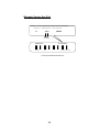
3DForce6200 series
nVIDIA GeForce™ 6200 series
User’s Manual
Version 7.00
Copyright © 2009 Jaton Corporation, USA
Contents
INTRODUCTION ......................................................................... 4
FEATURES AND SPECIFICATIONS ......................................... 5
SYSTEM REQUIREMENT .......................................................... 9
CHECK LIST ............................................................................... 9
HARDWARE DESCRIPTION.................................................... 10
DISPLAY DEVICES OUTPUT .................................................. 13
HARDWARE INSTALLATION.................................................. 15
INSTALLATION PROCEDURES ........................................................ 15
STEPS: ........................................................................................ 15
SOFTWARE INSTALLATION................................................... 17
á WINDOWS® 7 AND VISTA DRIVER INSTALLATION .................... 17
á WINDOWS® XP DRIVER INSTALLATION .................................. 20
á WINDOWS® 2000 DRIVER INSTALLATION .............................. 23
TECHNICAL ASSISTANCE...................................................... 26
FREQUENTLY ASKED QUESTIONS (FAQ) ....................................... 27
PINOUT AND SYNC FREQUENCIES ...................................... 30
ANALOG COLOR DISPLAY PINOUTS (DB 15) .................................. 30
CONVERSION TABLE: PIN ADAPTERS............................................. 30
9-TO-15 PIN CONVERSION TABLE ................................................. 31
DIGITAL VISUAL INTERFACE (DVI-I) CONNECTOR ........................... 31
TECHNICAL SUPPORT ................................................................... 32
HOW TO OBTAIN WARRANTY SERVICE .......................................... 33
LIMITED WARRANTY .............................................................. 35
OTHER LIMITS .............................................................................. 36
EXCLUSIVE OBLIGATION ............................................................... 36
OTHER STATEMENTS.................................................................... 36
TERMS AND CONDITIONS .............................................................. 37
SERVICES AGREEMENT:................................................................ 37
ENTIRE OBLIGATION ..................................................................... 38
REDUCING WARRANTY CLAIM REJECTIONS..................... 39
3
Introduction
3DForce6200 series video accelerators are based on nVIDIA GeForce™
6200 core technology. 3DForce6200 series feature NVIDIA
UltraShadow II technology designed to enhance the performance of
shadow-intensive games.
Powered by the proven NVIDIA CineFX 3.0 engine, these advanced
GPUs enable unlimited programmability and infinite program length,
allowing develops to create new class of advanced visuals and effects.
In addition, features such as displacement mapping enable the creation
of unique 3D characters and objects, allowing develops to alter a 3D
models appearance on an individual vertex basis. Through this
technique, developers can create ultra realistic models that fully interact
with the unique lighting of a particular environment. In addition, through
Shader Model 3.0 and the advanced CineFX 3.0 engine, game develops
can create complex lifelike effects like skin, hair and shadows that fool
the eye of even the most discriminating game enthusiast.
3DForce6200 series deliver unmatched video features and functionality
through the industry’s first on-chip video processor. This dedicated unit
on the GPU handles the lion’s share of the video processing load,
freeing up the CPU for other tasks. The video processor delivers MPEG
support for encoding and decoding of both analog and digital video
content, as well as high quality video scaling and filtering for impeccable
playback quality at any widow size. An integrated TV encoder allows you
to connect your PC to TV for direct to TV playback and advanced
adaptive de-interlacing technology provides smooth playback on
progressive displays.
Built on the foundation of the industry-renowned NVIDIA Unified Driver
Architecture (UDA), 3DForce6200 series deliver unmatched
compatibility with the widest range of games and applications for the
ultimate “install and play” experience. Equip yourself with a
3DForce6200 series GPU so you can play your games the way it’s
meant to be played.
Features and Specifications
3DForce6200 series
CineFX 3.0 Engine
The third-generation of the NVIDIA® CineFX™ engine unleashes the
power of the latest NVIDIA GPUs and streamlines the creation of
complex visual effects. Through the power of the Microsoft® DirectX®
9.0 Shader Model 3.0 and OpenGL® 1.5 APIs, programmers can now
develop shader programs utilizing these technologies and techniques:
Infinite length shader programs: With CineFX 3.0 there are
no hardware-imposed limitations on shader programs. The
technology and speed advancements of CineFX 3.0 ensure
that longer programs will run blazingly fast.
Dynamic flow control: Additional looping/branching options
and new subroutine call/return functions give programmers
even more choices for writing efficient shader programs.
Displacement mapping: CineFX 3.0 allows vertex processing
with textures, providing a new level of depth and realism to
every component, surface, and character in a scene.
Displacement mapping allows developers to make subtle
changes in a model’s geometry with very little computational
cost.
Vertex frequency stream divider: Effects can be efficiently
applied to multiple characters or objects in a scene, providing
individuality where models are otherwise identical.
Multiple Render Target (MRT) technology: MRTs allow for
deferred shading, a technique where the lighting of a scene
can be done after rendering all of the geometry, eliminating
multiple passes through the scene. Photorealistic lighting can
be created while avoiding unnecessary processing time for
pixels that do not contribute to the visible portions of an image.
With the increased horsepower provided by the CineFX 3.0 engine,
developers can create more unique game features and effects than ever
before. New effects include subsurface scattering, providing depth and
realistic translucence to skin and other surfaces; soft shadows for
sophisticated lighting effects; accurately represented environmental and
ground shadows; and global illumination for incredibly photorealistic
lighting. All of these effects can be combined to create intricate,
detailed, true-to-life scenes that completely immerse you in the game
environment.
NVIDIA CineFX 3.0 is poised to unleash a new level of programming
creativity. With full DirectX 9.0 Shader Model 3.0 support, the newest
3DForce6200 series will soon power a new generation of games with
unmatched realism, digital worlds with mind-blowing complexity, and
lifelike characters that move through cinematic-quality environments.
Intellisample Technology
The industry’s fastest antialiasing delivers ultra-realistic visuals, with no
jagged edges, at lightning-fast speeds. Visual quality is taken to new
heights through a new rotated grid sampling pattern.
UltraShadow II Technology
3DForce6200 series of GPUs delivers the patent-pending NVIDIA®
UltraShadow™ II technology, which can be applied to today’s games to
build stunning visual effects and to create distinctive digital
environments. With a system powered by a 3DForce6200 series GPU,
anytime a game or application calculates shadows, UltraShadow II will
enhance the overall performance. With UltraShadow II hardware, the
more passes that are required for the lighting and shadow calculations
in a scene, the more significant the performance improvement, with the
most complex scenes achieving the most noticeable results.
Thus, emerging next-generation games, that employ multiple light
sources with many visible objects in each scene—such as Doom III from
id Software—will see dramatic improvements in execution speeds. The
technology advancements in UltraShadow II also deliver a 4×
performance increase (compared to the previous generation) for passes
involving shadow volumes.
NVIDIA UltraShadow II gives developers the ability to calculate shadows
much more quickly by eliminating unnecessary areas from
consideration. By defining a bounded portion of a scene (called “depth
bounds”), and focusing calculations only on the area most affected by
the light source, developers can greatly accelerate the shadow
generation process. With the ability to fine-tune shadows within critical
regions, developers create incredible visualizations that mimic reality,
and still achieve awesome performance for fast-action games.
UltraShadow II also works perfectly with NVIDIA® Intellisample 3.0
technology to ensure that shadow edges are properly antialiased.
Unified Driver Architecture (UDA)
The Nvidia UDA guarantees forward and backward compatibility with
software drivers. This simplifies upgrading to a new NVIDIA product
because all NVIDIA products work with the same driver software.
6
nView Multi-Display Technology
The nView hardware and software technology combination delivers
maximum flexibility for multi-display options and provides
unprecedented end-user control of the desktop experience.
Digital Vibrance 3.0
This feature allows the user to adjust color controls digitally to
compensate for the lighting conditions of their workspace, in order to
achieve accurate and bright colors in all conditions.
128-Bit Studio-Precision Computation
128-bit studio-precision computation through the entire pipeline prevents
image defects due to low precision and ensures the best image quality
for even the most demanding applications
Full-Speed 32-Bit Color Precision
Delivers increased image quality with no performance compromise.
Full MPEG Support
Delivers a stunning video experience through encoding and decoding of
analog and digital content.
Advanced Adaptive De-Interlacing
Smoothes video and DVD playback on progressive displays
Video Scaling and Filtering
High-quality scaling and filtering technology improves video playback
quality at any window size, including full-screen HDTV resolutions.
Integrated TV Encoder
Provides best-of-class TV-out functionality for resolutions up to
1024x768.
Microsoft® DirectX® 9.0 Optimizations and Support
Ensures the best performance and application compatibility for all
DirectX 9 applications.
OpenGL® 1.5 Optimizations and Support
Ensures the best performance and application compatibility for all
OpenGL applications.
Dual 400MHz RAMDACs
Blazing-fast RAMDACs support dual QXGA displays with ultra-high,
ergonomic refresh rates–up to 2048x1536@85Hz.
7
Compatibility
•
NVIDIA Unified Driver Architecture (UDA)
•
Fully compliant with OpenGL 1.5
•
Microsoft DirectX 9.0
•
WHQL-certified for Windows 7, Windows Vista, Windows XP,
Windows 2000
PERFORMANCE
•
Up to 1.2 billion texels per second fill rate
•
Up to 225 million vertices per second
•
128-bit memory interface
•
4 Pixels/Clock Rendering Pipeline
•
400MHz RAMDACs support
8
System Requirement
•
•
•
Intel Pentium® P4 or compatible system with AGP 4X /
8X extension Slot
Hard Drive with at least 100MB Free space
MS Windows® 7/Vista/2000/XP operating system
Check List
•
•
•
•
•
•
3DForce6200-256, 3Dforce6200Xe, 3Dforce6200XeTwin, 3Dforce6200Xe-Twin-LP, 3DForce6200Twin or
3DForce6200Twin-LP Multimedia Accelerator
Mini-DIN 9-pin (TV-Out) converter cable for Composite
RCA or S-Video Out connection - 3DForce6200-256,
3Dforce6200Xe
DVI to RGB converter - 3DForce6200-256,
3Dforce6200Xe
Converter cable – converts MD-9pin to DB-15 VGA –
3DForce6200Twin-LP, 3Dforce6200Xe-Twin-LP
Software & Documents CD
Quick Start Guide (Printed)
Hardware Description
3Dforce6200-256 / 3Dforce6200Xe
Low profile configuration
3Dforce6200Twin / 3Dforce6200Xe-Twin
3Dforce6200Twin-LP / 3Dforce6200Xe-Twin-LP
11
Product name / PCB version
Core Chipset
PCB Size
Memory Size
3DForce6200-256
82338B
nVIDIA GeForce 6200
W=6.1” X H=2.5”
32M*16 x 4 DDR SDRAM
256MB
3DForce6200-Twin
82338E
nVIDIA GeForce 6200
W=6.1” X H=2.7”
32M*16 x 4 DDR SDRAM
256MB
3DForce6200-Twin-LP
82338E
nVIDIA GeForce 6200
W=6.1” X H=2.7”
32M*16 x 4 DDR SDRAM
256MB
3DForce6200Xe
82348B
nVIDIA GeForce 6200
W=6.36” X H=2.58”
64M*16 x 4 DDR2 SDRAM
512MB
3DForce6200Xe-Twin
82348E
nVIDIA GeForce 6200
W=6.36” X H=2.58”
64M*16 x 4 DDR2 SDRAM
512MB
3DForce6200Xe-TwinLP
82348E
nVIDIA GeForce 6200
W=6.36” X H=2.58”
64M*16 x 4 DDR2 SDRAM
512MB
Accessories for VGA cards are sold separately. Please go to
http://Store.anvshopper.net for more details
12
Display Devices Output
3Dforce6200-256 / 3Dforce6200Xe
Low profile configuration
13
1.
RGB out - DB15 VGA connector to analog monitor.
2.
DVI out - DVI connects to LCD display panel.
3.
DVI converts to RGB with DVI-RGB converter for Dual RGB out.
4.
TV-Out – Mini-DIN 9-pin (TV-Out) converter cable for Composite RCA or SVideo Out connection
3Dforce6200Twin / 3Dforce6200Xe-Twin
3Dforce6200Twin-LP / 3Dforce6200Xe-Twin-LP
Converter Cable
DIM-9Pin
CRT
Monitor
DB 15 VGA
DB 15 VGA Connector
CRT
Monitor
14
Hardware Installation
Installation Procedures
!! WARNING!!
Discharge static electricity by
touching the GROUND such
as metal part of your case
connected with good power
ground before you handle the
electronic circuit boards.
The manufacturer assumes no liability for any damage, caused directly
or indirectly, by improper installation of any components by unauthorized
service personnel. If you do not feel comfortable performing the
installation, consult with a qualified computer technician.
Steps:
1.
Turn OFF all powers to your system, including any peripherals (printer,
external drives, modem, etc.).
2.
Disconnect the power cord and the monitor cable from the back of the
computer.
3.
Unfasten the cover mounting screws on your system and remove the
system cover. Refer to your system user manual for instructions to
determine the location of the mounting screws.
4.
Remove the retaining screw that holds the slot cover in place. Slide
the slot cover out and put the screw aside (you will need it to secure
the adapter).
5.
To install the adapter in AGP expansion slot, carefully line up the goldfingered edge connector on the adapter directly above the expansion
slot connector on the motherboard. Then press the adapter into place,
completely. Use the (remaining) screw you removed to secure the
adapter-retaining bracket in place.
6.
Replace the computer cover. Secure the cover with the mounting
screws you removed in Step 3.
You have now completed the installation of your new graphics adapter on your
system.
15
Upgrade Steps:
Add or change your video adapter to an existing system, you
may precede a few steps before you install the new hardware
and software (video display driver). The followings are some of
the considerations:
1. To add a new adapter, ensure the mainboard has available
IRQ for new devices, and there is no conflict between each
other.
2. If you are installing the video card into a system that has a
previous version of Nvidia Display Driver. It is highly
recommended to remove the previous driver before installing
a new version. To remove previous driver safely with new
video card installed please do the following: 1) Press F8
during Windows boot to select and enter SAFE mode. 2)
Enter Control Panel and click on “Add Remove Programs” 3)
Uninstall previous versions of Nvidia Video Display Driver.
3. If you try adding this video adapter to an ALL-IN-ONE
mainboard (which video port built-in already), then you have
to disable that port first. Otherwise, that will be a problem for
the new video adapter setup.
4. The driver installation for system upgrade is the same as
below, if error occurs when you proceed to step 1, 2 or 3,
please consult with your system dealer or the existing
hardware manufacturer support.
16
Software Installation
á Windows® 7 and Vista Driver Installation
InstallShield® Program:
Microsoft Windows® 7 and Vista detects this new hardware and places
appropriate display driver from its system folder automatically - it doesn’t
matter if you have added a new driver or changed the existing one. To
maximize the video board acceleration and increase its performance,
you may install the manufacturer’s display driver as follows:
1. Click Yes to continue
2.
Click on “Next” to continue the process.
3.
Click on “Yes” to agree to license agreement and continue.
18
4.
Click on “Finish” to complete the installation.
19
á Windows® XP Driver Installation
InstallShield® Program:
Microsoft Windows® XP detects this new hardware and places
appropriate display driver from its system folder automatically - it doesn’t
matter if you have added a new driver or changed the existing one. To
maximize the video board acceleration and increase its performance,
you may install the manufacturer’s display driver as follows:
1. Autorun feature brings-up the “Welcome Screen”, and you may
point to “Display Driver” and then press on it.
2. Microsoft InstallShield® Wizard has start loading its setup process;
please wait until it has completed.
3. Click on “Next” to continue the process.
21
4. The Windows system will copy all driver files from source media to
your local hard disk; please wait until the process has completed.
5. Click on “Finish” to restart your computer, the new display driver will
be in place after Windows boots-up.
á Windows® 2000 Driver Installation
InstallShield® Program:
Microsoft Windows®2000 detects this new hardware and places
appropriate display driver from its system folder automatically - it doesn’t
matter if you have added a new driver or changed the existing one. To
maximize the video board acceleration and increase its performance,
you may install the manufacturer’s display driver as follows:
1. Autorun feature brings-up the “Welcome Screen”, and you may
point to “Display Driver” and then press on it.
2. Microsoft InstallShield® Wizard has start loading its setup process;
please wait until it has completed.
3. Click on “Next” to continue the process.
24
4. Click on “Finish” to restart your computer, the new display driver will
be in place after Windows boots-up.
Notice:
We believe that the all the installation steps mentioned above
are clear from manufacturer software’s CD to your operating
system. Any procedures other than these processes have not
been specified.
25
Technical Assistance
Q: Why is the display shifted or changed sizes when I switch display modes?
Explain and Suggestion:
Some monitors lack auto-sizing features or just do not synchronize properly to
the video board output. In some cases, horizontal and vertical display
adjustments may be necessary. Use the monitor control panel functions to adjust
screen.
In other cases, mode type and refresh rate adjustments may be necessary. Use
the utility program, which provided by video card manufacturer or production
developer. To center the display with normal type (mode 3), and to reduce
(decrease) the refresh rate with the monitor's specification.
Q: What kind monitors can display 800x600 modes or higher resolution mode?
Explain and Suggestion:
To display 800x600 resolution at 60Hz refresh rate, the monitor must be capable
of synchronizing a 31.5KHz horizontal scan rate (e.g., NEC 2A, 3D). At 72Hz
refresh rate, the monitor must be capable of synchronizing a 48.0KHz scan rate
(e.g., Sony HG 1304, NEC 4D, 5D, Seiko 1450).
To display 1024x768 interlaced mode; the monitor must be capable of
synchronizing a 35.5KHz horizontal scan rate (e.g., NEC 3D, Seiko 1430 or
1440). To display 1024x768 non-interlaced mode at 60Hz, the monitor must be
capable of synchronizing a 48.7KHz scan rate (e.g., Sony HG 1304, NEC 4D,
5D, Seiko 1450).
To display 1024x768 non-interlaced mode at 70Hz, the monitor must be capable
of synchronizing a 56.4KHz scan rate (e.g., NEC 4D).
Q: System hangs-up after installing video driver.
Explain and Suggestion:
Today, most video drivers are developed for 32-bit processing and may require a
channel to Code/Decode. Conflict between device drivers and TSR (terminateand-stay-resident) programs will inverted the display, and are particularly
effectual at crashing computer. The most effective way to check for conflicts is to
replace with the original video driver, or delete and re-install the current video
driver to the system.
Accomplishing IRQs (Interrupt Request Query) settings or troubleshooting the
conflicts on hardware source may necessary. Most AGP video cards designed for
Plug-n-Play, that means video card IRQ's setup which controls by main board’s
(motherboard) circuitry and BIOS. Physically pulling out other devices from
system, and re-starts the computer. Confirm and modify your IRQ addresses with
qualified computer technician.
Q: Multiple images or unreadable screen after loading video driver.
Explain and Suggestion:
There are a variety of reasons why the display might be distorted. One common
reason is a monitor mis-match. Some older multi-frequency monitors are unable
to switch video modes without being turned off, then turned on again.
If the problem occurring in windows, make sure that you have loaded that proper
video driver, and that the driver is compatible with the monitor being used. Try reconfiguring your application software to use a compatible video mode. If problem
persist in windows, load the standard generic VGA driver. The generic VGA
driver should function properly with virtually every video board and VGA (or
SVGA) monitor available.
If that is an unsatisfactory solution, you may have to upgrade to a monitor that
supports the desired video mode.
Some new monitors are also synchronizing this problem because built-in DDC
(Data-Digital-Channel) feature. Sometime that DDC automatically setup the
display frequency without loading video driver. Try to turn it off, or change
settings of monitor type in your system.
Q: Selection of color, resolution and refresh rate combination that always backs
to default after restart the system.
Explain and Suggestion:
Accordingly, there must be a bug (defected source-code) in video driver, or in the
system. Debug the source-code or fix the error in video driver that should be
done by the driver developer. Likewise, upgrade the video driver from the
manufacturer or from the original software developer is necessary.
Frequently Asked Questions (FAQ)
Q1 Why do we need 3D graphics capability in our PC?
Answer
3D technology is becoming increasingly important (and common) not only in
games, but also in other applications such as VRML, which allows 3D scene
descriptions in Web applications. 3D technology is used for image editing,
modeling, and an increasing number of in home and business applications. In
games, as well as other applications, 3D acceleration not only allows better
visual qualities and more realistic scenery attributes than software alone, but it
also allows a higher frame rate, which translates into a more interactive
experience for the end user.
27
Q2 What does “Rendering Engine” mean?
Answer
“Rendering Engine” generically applies to the part of the graphics engine that
draws 3D primitives, usually triangles. In most implementations, the rendering
engine is responsible for interpolation of edges and "filling in" the triangle.
Q3 What does the set-up engine do in a graphics controller?
Answer
A set-up engine allows drivers to pass triangles in the form of raw vertex
information; whereas, most common designs force triangles to be pre-processed
for the rendering engine in terms of delta values for edges, color, and texture.
Q4 Why does a 3D graphics chip need to have both a rendering engine and a
setup engine?
Answer
Any “3D application”, a game, VRML, or modeling package, can benefit from 3D
rendering. This is especially true of an application that uses texturing extensively,
because texturing and texture filtering are very intensive operations at the pixel
level in terms of CPU operations and demands for memory bandwidth. Without a
set-up engine in a graphics controller, the CPU has to calculate the delta values
for edges, color, and textures; the drivers need to handle ten (10) times more
extensive data. This results in slower 3D pipeline operations between the CPU
and the graphics controller.
Q5 If we use powerful CPUs, such as a Pentium™ 200, can a standard 2D
graphics card achieve 3D performance?
Answer
Yes and no. Software rendering can take advantage of "tricks" learned by force of
necessity through years of trial and error. With such stratagems, the speed of
software rendering for simple scenes can approach that of low-level hardware 3D
rendering. On the other hand, as scenes become more complex (or frame sizes
become larger), there are conflicts between using the CPU for high-level game
logic, geometry, lighting, and rendering, all of which increase their demands. No
current CPU or system can perform advanced quality-enhancements (bilinear
filtering and alpha blending) in real time. Even general case texture mapping with
RGB lighting is too much for the current CPU generation.
Q6 What does "software 3D" mean?
Answer
28
Software 3D is generally used to mean using non-specific (2D) hardware in
conjunction with the CPU to render for 3D applications. Some of these
techniques allow usable 3D applications when high-powered and/or MMX™equipped CPU's are employed along with special-case software optimization
techniques. As stated above, SW 3D can achieve credible results with today's
(software optimized) applications, but the rising popularity of good 3D hardware
at the consumer price level is inexorably compelling the public to expect
hardware level scene enhancements and frame rates.
29
Pinout and Sync Frequencies
Analog Color Display Pinouts (DB 15)
PIN
FUNCTION
1
Red Video1
2
3
Green Video1
Blue Video1
4
5
6
7
8
9
10
11
12
13
14
15
Not Used
Ground
Red Return (ground)
Green Return (ground)
Blue Return (ground)
Vcc (+5v DDC Power)
Sync Return (ground)
Monitor ID (not used)
SDA (DDC support)
Horizontal Sync
Vertical Sync
SCL (DDC support)
Note:
Analog monochrome type monitors use green video for all video input
and ignore red and blue video.
Conversion Table: Pin Adapters
If you will be using a 9-to-15-pin adapter cable to link your 9-pin monitor
connector to the 15-pin accelerator card connector, check Table carefully before
you install the cable. The 9-to-15 pin adapter cables are available from a variety
of sources, but they need to match the specifications in Table to work properly
with your new card.
The adapter cable requires a D-shaped 9 pin female connector and a D-shaped
15 pin male connector.
9-to-15 Pin Conversion Table
9 PIN SIGNALS
PIN NO.
Red
Green
Blue
Horz Sync
Vert Sync
Red Ground
Green Ground
Blue Ground
Sync Ground
15 PIN SIGNALS
1
2
3
4
5
6
7
8
9
PIN NO.
Red
Green
Blue
Horz Sync
Vert Sync
Return Red
Return Green
Return Blue
Digital Ground
Ground
Analog Video Signals
Black Level = 0 V
Full Intensity (White) Level = +0.7 V
Digital Visual Interface (DVI-I) Connector
1
8
17
C1 C2
24 C3 C4
24 pin DVI FEMALE connector built-in onboard.
Pin Number
Signals
1
TMDS Data 2 -
2
TMDS Data 2 +
3
TMDS Data 2 Shield
4
No Connection
5
No Connection
6
DDC Clock
7
DDC Data
8
No Connection
9
TMDS Data 1 -
31
1
2
3
13
14
6
7
8
10
5
10
TMDS Data 1 +
11
TMDS Data 1 Shield
12
No Connection
13
No Connection
14
+5 V Power
15
Ground (for +5 V)
16
Hot Plug Detect
17
TMDS Data 0 -
18
TMDS Data 0 +
19
TMDS Data 0 Shield
20
No Connection
21
No Connection
22
TMDS Clock Shield
23
TMDS Clock +
24
TMDS Clock <
Technical Support
In the event you have a technical problem with this product, please
read the README files in the software CD_ROM. Updated drivers are
available through Jaton Web site. Have following information handy
when you contact technical support:
;
;
;
;
Name of the product.
Software Driver and Version.
System Information, such as CPU speed, BIOS version, Monitor
Specification, etc.
Description of the problems including any error messages.
Telephone:
(510) 933-8886 (Mon. - Fri. 9am-5pm PST)
FAX:
(510) 933-8887
email:
[email protected]
Website:
www.jaton.com
32
How to Obtain Warranty Service
In the worldwide contact:
www.jaton.com
In United States contact:
Jaton Corporation.
Service Center
47677 Lakeview Blvd.,
Fremont, CA 94538
Tel: 510-933-8886
Fax: 510-933-8887
In Taiwan contact:
Jaton Technology Co., Ltd.
10F, NO.194, SEC.3, TA TUNG RD., HIS-CHIH,
TAIPEI, TAIWAN R.O.C.
Tel : 886-2-8647-1899
Fax : 886-2-8647-2679
In Australia contact:
Jaton Technology pty, Ltd.
Unit 8, 41-49 Norcal Road,
Nunawading, Vic 3131 Australia
Tel: (Mel) 03 9873 3999
(Syd) 02 9476 8781
Fax 03 9873 3933
33
FCC SHIELDED CABLE WARNING:
This equipment has been tested and found to comply with the limits for a Class B digital
device, pursuant to Part 15 of the FCC Rules. Operation is subject to the following
conditions: (1) this device may not cause harmful interference, and (2) this device must
accept any interference received, including interference that may cause undesired
operation,
“SHIELD INTERFERENCE CABLE (S) MUST BE USED ACCORDING TO FCC 15.27©.”
CAUTION:
Changes or modifications not expressly approved by the Manufacturer could void your
authority to operate this equipment in accordance with FCC rules and regulations.
SOFTWARE LICENSE AGREEMENT:
The Company grants the customer a non-exclusive, non-transferable license to use the
software in this package for internal use on a single computer system. No other license of
any kind is granted to any part of the product or any of the intellectual property therein.
Limited Warranty
Manufacturer warrants that the products sold hereunder are free
from defects in material and workmanship for a period of two (2)
years from manufacturing date. This limited warranty applies
only to the original purchaser of Jaton Product and is not
transferable. This limited warranty does not apply if failure to the
Product Registration, or over thirty (30) days from purchase
(original invoice date). This Limited Warranty does not cover any
incompatibilities due to the user’s computer, hardware, software
or any related system configuration in which the Jaton Products
interfaces. Manufacturer does not guarantee the compatibility of
the video cards with any hardware components, systems or
software that’s available in the market. If a product is deemed
incompatible by Manufacturer tech support, the product in
question is therefore not defective and thus no warranty will be
provided. It is the buyer’s sole responsibility to do their own
research and determine if the products to be purchased are
compatible to the hardware components, systems or software
they intend to use with. Proof of purchase will be requiring
before any consideration by Manufacturer occurs.
TRADEMARK AND COPYRIGHT:
This product incorporates copyright protection technology that is
protected by U.S. patents and other intellectual property rights. Use of
this copyright protection technology must be authorized by Macrovision,
and is intended for home and other limited viewing uses only unless
otherwise authorized by Macrovision. Reverse engineering or
disassembly is prohibited.
All Trademarks and Registered Trademarks belong to respective
owners.
©2006 Jaton Corporation. All rights reserved.
Other Limits
The forgoing is in lieu of all other warranties, expressed or
implied. Including but not limited to the implied warranties
of merchantability and fitness for a particular purpose.
Manufacturer does not warrant against damages or defects
arising out of improper or abnormal use of handling of the
products; against defects or damages arising from improper
installation (where installation is by persons other than
Manufacturer), against defects in products or components not
manufactured or installed by Manufacturer, or against damages
result from non-manufacturer made products or components.
This warranty does not apply if accident, abuse, nor misuse has
damaged the Product. This warranty also does not apply to
products upon which repairs have been affected or attempted by
persons other than pursuant to written authorization by
Manufacturer.
Exclusive Obligation
This warranty is exclusive. The sole and exclusive obligation
of Manufacturer shall repair or replace the defective products in
the manner and for the period provided above. Manufacturer
shall not have any other obligation with respect to the Products
or any part thereof, whether based on contract, tort, and strict
liability or otherwise. Under no circumstances, whether based on
this Limited Warranty or otherwise, Manufacturer shall not be
liable for incidental, special, or consequential damage.
Other Statements
Manufacturer’s employees or representatives’ ORAL OR
OTHER WRITTEN STATEMENTS DO NOT CONSTITUE
WARRANTIES, shall not be relied upon by Buyer, and is not a
part of the contract for sale or this Limited Warranty.
36
Terms and Conditions
Direct Jaton Customer:
This warranty applies only for a
period of two (2) years from
purchase date of Jaton original
invoice.
Reseller/ Vendor:
This warranty applies only for a
period of two (2) years from
manufacturing date.
Registered User:
This warranty applies only for a
period of two (2) years from
purchase date and register within 30
days of purchase date from legal
reseller.
Others:
If the products do not conform to this
Limited Warranty (as herein above
described), Manufacturer should
charge services such as repair,
replacement whether based on its
costs. Shipping and installation of the
replacement Products or
replacement parts shall be at User’s
expanse.
Services agreement:
(1) All applicants shall complete service request form from
Manufacturer.
(2) All returned checks will be charged a $20.00 fee by
Manufacturer.
(3) All repair and replacement services allow 4-6 weeks from
the date of receiving by Manufacturer.
(4) All products without warranties require service processing
fee $20 (payment in advance), which is not refundable.
37
Entire Obligation
This Limited Warranty states the entire obligation of
Manufacturer with respect to the Products. If any part of this
Limited Warranty is determined to be void or illegal, the
remainder shall remain in force and effect. Some states do not
allow limitation of implied warranties, or exclusive or limitation on
product incidental or consequential damages, so above limitation
may not apply to you. This warranty gives you specific legal
rights. You may have other rights, which may vary from state to
state.
This warranty applies only to this product, and is governed by
the law of the State of California.
38
Reducing Warranty Claim Rejections
To reduce the potential of incurring damages not covered by
Manufacturers warranties, we strongly recommend the following:
•
Read your manuals before installing peripherals
and/or before making changes to the machine’s
configuration;
•
Ask your dealer if there are any known problems
with the system requirements or installation
procedures for any add-on products that your are
purchasing;
•
Buy industry standard products where compatibility
issue are less likely to surface;
•
If you are unsure about installation for a new
product, contact your dealer’s service department.
We believe it is important for you to know and understand what
your warranty coverage provides and what it does not.
We also want you to be aware that most hardware warranties
only relate to the function of the hardware. In most cases, no
assurances are given by the manufacturer that the hardware
item will work in conjunction with any other hardware item. If a
computer product is not working because it is not compatible
with another product, or because it has not been properly
installed and set-up, the manufacturer does not pay for the
service time. To help avoid these inconveniences, contact a
professional consultant that one can help you determine the
possibility of incompatibility issue before you purchase add-on or
accessories.
Warranty Service Use Only
Serial Number - ten or eleven digit code, the serial number consists of the following parts:
Packaging Type
Manufactured Date Code
A
00 8
Production Numerical Code
000015
Year Month
XXXXX-XXX-XX
xxxx/xxxx
S/N: A008000015
00.0
XXXX XX XXXXXX
Product Label and Manufactured Date Code
40