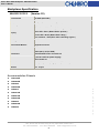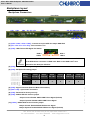
1
4-Port Mini-SAS Backplane 80H10321513C0
User’s Manual
CHENBRO
Storage Chassis
4-Port Mini-SAS Backplane
80H10321513C0
September / 10 / 2009
15Fl., No.150, Jian Yi Road, Chung Ho City, Taipei Hsien, Taiwan R.O.C.,
Tel: +886 2 82265500 Fax: +886 2 82265392 Email: [email protected]
1
w w w . c h e n b r o . c o m
User’s Manual
4-Port Mini-SAS Backplane 80H10321513C0
User’s Manual
Copyright
Copyright © 2006 Chenbro Micom Co., Ltd.. All rights reserved.
Unless otherwise indicated, all materials in this manual are copyrighted by Chenbro Micom Co., Ltd.. All rights
reserved. No part of this manual, either text or image may be used for any purpose other than internal use within
purchasing company. Therefore, reproduction, modification in any form or by any means, electronic, mechanical or
otherwise, for reasons other than internal use, is strictly prohibited without prior written permission.
Chenbro Micom Co., Ltd. reserves the right to make improvement and modification to the products indicated in this
manual at any time.
Specifications are therefore subject to change without prior notice.
Information provided in this manual is intended to be accurate and reliable. However, Chenbro Micom Co., Ltd.,
assumes no responsibility for its use, nor for any infringements upon the rights of third parties, which may result from
its use.
Technical Support
Chenbro works hard to offer our customers maximum performance from our chassis. But in case you have
any problem with our product you can find supports from the following resources.
Web Support
Detail information of our products is in our website. You can find technical updates, installation guides, FAQs,
technical specifications and more. Our web address is: www.chenbro.com.
Email Support
You can also fill out the technical support form at our Technical Support page. You technical issue inquiries will be
sent directly to our support professionals.
Phone Support
w w w . c h e n b r o . c o m
You can also contact Chenbro HQ or branch office for immediate support; contact Information is as following:
Chenbro HQ
Chenbro Europe B.V.
Chenbro Micom (USA) Inc.
Tel: 886-2-8226-5500
Tel: 31-40-295-2045
Tel: 1-909-947-3200
Fax: 886-2-8226-5423
Fax: 31-40-295-2044
Fax : 1-909-947-4300
15Fl., No.150, Jian Yi Road, Chung Ho City, Taipei Hsien, Taiwan R.O.C.,
Tel: +886 2 82265500 Fax: +886 2 82265392 Email: [email protected]
2
4-Port Mini-SAS Backplane 80H10321513C0
User’s Manual
Contents
Copyright......................................................................................................................................................2
Technical Support......................................................................................................................................2
Contents .......................................................................................................................................................3
Revision History.........................................................................................................................................4
Backplane Specification ..........................................................................................................................5
Accommodation Chassis.................................................................................................................5
Backplane Layout ......................................................................................................................................6
Backplane Connectors .....................................................................................................................6
Backplane Assembly.................................................................................................................................8
LED Board Specification........................................................................................................................11
1U LED Board....................................................................................................................................11
2U~4U LED Board ............................................................................................................................12
5U LED Board and Display Board ...............................................................................................13
Power Supply Alarm Mute Connector Definition.....................................................................14
Power Supply Alarm Signal Connector Definition ..................................................................14
Mini-SAS Cables.......................................................................................................................................15
Backplane and LED Board Wiring .......................................................................................................17
Chassis Assembly Example..................................................................................................................17
Example for RM11704B / RM12404B Mini-SAS backplane wiring.......................................17
Example for RM21508B chassis Mini-SAS backplane wiring ..............................................18
Example for RM31212B Mini-SAS backplane wiring ..............................................................19
Example for RM41416B Mini-SAS backplane wiring ..............................................................20
Example for RM51924B chassis Mini-SAS backplane wiring ..............................................21
w w w . c h e n b r o . c o m
15Fl., No.150, Jian Yi Road, Chung Ho City, Taipei Hsien, Taiwan R.O.C.,
Tel: +886 2 82265500 Fax: +886 2 82265392 Email: [email protected]
3
4-Port Mini-SAS Backplane 80H10321513C0
User’s Manual
Revision History
Date
March / 01 / 2009
Sep. / 10 / 2009
Modifications
z First release
z Add CN2 Pin Definition
w w w . c h e n b r o . c o m
15Fl., No.150, Jian Yi Road, Chung Ho City, Taipei Hsien, Taiwan R.O.C.,
Tel: +886 2 82265500 Fax: +886 2 82265392 Email: [email protected]
4
4-Port Mini-SAS Backplane 80H10321513C0
User’s Manual
Backplane Specification
80H10321513C0
(Version C0)
Host Interface
Mini-SAS (SFF-8087)
HDD Interface
SAS (22+7) and SATA-II compatible
Hot-Swap
Yes, allows user to replace HDD on line
LED indicates HDD status (Defined by Chenbro)
Power LED – Blue ( When HDD is present )
Display
Access LED –Green (When HDD is busy )
Error indicator – Red (Error when retreating signals )
Cooling
Five Fan connectors
Environment Monitor
Temperature sensor
1. SFF-8087 x1 to host
2. SAS (22+7) x4 (for HDD )
Connectors
3. Standard 4P Power connector x2
(+5V & +12V from power supply)
4. Box header x1
Dimension
419.5 (Width) x 23.0 (Height) x 2.4 (Thickness) mm
Material
FR4 4 layer
Accommodation Chassis
RM11704B
z
RM12404B
z
RM13204
z
RM21508B
z
RM23212
z
RM31212B
z
RM41416B
z
RM51224B
z
RM51424
z
RM51924B
z
RM91250
w w w . c h e n b r o . c o m
z
15Fl., No.150, Jian Yi Road, Chung Ho City, Taipei Hsien, Taiwan R.O.C.,
Tel: +886 2 82265500 Fax: +886 2 82265392 Email: [email protected]
5
4-Port Mini-SAS Backplane 80H10321513C0
User’s Manual
Backplane Layout
Backplane Connectors
Front View
CN11
CN7
CN5
CN21
CN6 JF1 JF2 JF3
CN31
Rear View
CN1
CN41
JF4 JF5 CN4 CN3 CN2
CN9 CN10 CN8
(1) [CN11 / CN21 / CN31 / CN41] : Connect to 22-pin SATA-II or 29-pin SAS HDD
(2) [JF1 / JF2 / JF3 / JF4 / JF5] : Fan connectors 1~5
(3) [CN2] : HDD Failure LED Signal Pin Header
HDD 4
HDD 3
HDD 1
HDD 2
Connect the 4-pin HDD LED cable (26H113322-001) from CN2 to the CATHODE
of the HDD failure connector on RAID card. Refer to the RAID card’s user
manual for the detail pin definition.
(4) [CN3] : Reserved for factory use only
(5) [CN4] : Backplane ID setting jumper
Jumper
Setting
Close
Pin 3 & 4
Close
Pin 5 & 6
Close
Pin 7 & 8
Close
Pin 9 & 10
Close
Pin 11 & 12
1
2
3
4
5
6
(6) [CN5] : Signal connector (Board to Board Connection)
(7) [CN6 / CN7] : 4-pin Power connectors
(8) [CN8] : Reserved for factory use only
(9) [CN9] : SGPIO HDD fail function jumper
Jumper Closed: Enable SGPIO HDD Failure Signal (Default)
Jumper Opened: Disable SGPIO HDD Failure Signal
(10) [CN10] : SGPIO HDD access function jumper
Jumper Closed: Enable SGPIO HDD Access Signal
Jumper Opened: Disable SGPIO HDD Access Signal (Default)
15Fl., No.150, Jian Yi Road, Chung Ho City, Taipei Hsien, Taiwan R.O.C.,
Tel: +886 2 82265500 Fax: +886 2 82265392 Email: [email protected]
6
w w w . c h e n b r o . c o m
Backplane
ID
Close
Pin 1 & 2
4-Port Mini-SAS Backplane 80H10321513C0
User’s Manual
(11) [CN1] : Mini-SAS connector
Pin Definition: SFF-8087 Mini-SAS 36-pin cable plug and receptacle connectors
B18
B1
B18
A1
A18
A18
Sideband Definition: The following table defines the SGPIO signal assignments for the Mini-SAS
receptacle connector
Pin Number
Pin
Signal
A8
Sideband 0
SClock
A9
Sideband 1
SLoad
A10
Sideband 2
Ground
B9
Sideband 3
Ground
B10
Sideband 4
SDataOut
B11
Sideband 5
SDataIn
A11
Sideband 6
Reserved
B8
Sideband 7
*SGPIO Enable / Disable
* The following table shows the SGPIO function which is related to the jumper setting of CN9 & CN10
connector.
CN10
SGPIO
Pin B8 Signal
Close
Close
Enable HDD failure and activity signal via SGPIO
Low
Close
Open
Enable HDD failure signal via SGPIO
Low
Open
Close
Enable HDD activity signal via SGPIO
Low
Open
Open
Disable HDD failure and activity signal via SGPIO
High
15Fl., No.150, Jian Yi Road, Chung Ho City, Taipei Hsien, Taiwan R.O.C.,
Tel: +886 2 82265500 Fax: +886 2 82265392 Email: [email protected]
7
w w w . c h e n b r o . c o m
CN9
4-Port Mini-SAS Backplane 80H10321513C0
User’s Manual
Backplane Assembly
The Chenbro 4-Port Mini-SAS Backplane can be assembled on Chenbro Storage Server Chassis only. Please
refer to the Chassis Quick Installation Guide for detail information.
Figure 1: Front and Rear View of 3U Backplane assembly set
(Using two 2U Backplane assembly sets)
15Fl., No.150, Jian Yi Road, Chung Ho City, Taipei Hsien, Taiwan R.O.C.,
Tel: +886 2 82265500 Fax: +886 2 82265392 Email: [email protected]
8
w w w . c h e n b r o . c o m
Figure 2: Front and Rear View of 4U Backplane assembly set
4-Port Mini-SAS Backplane 80H10321513C0
User’s Manual
(A) Example of assembly procedure for RM31212B chassis
1. Get the complete 3U backplane assembly set (with three backplanes) ready and make sure the
backplane guide rail is installed before backplane assembly.
2. Make sure the backplane ID is configured properly from bottom to top with starting from #1 to #3.
3. Slide the backplane assembly set into the chassis.
4. Fix the backplane assembly set with screws on both sides of chassis.
5. Connect the LED board signal cable for each backplane and LED board.
6. Refer to “Backplane wiring” session for cable connection.
1
Backplane ID #3
Backplane ID #2
2
Backplane ID #1
3
4
Fix Screws
4
w w w . c h e n b r o . c o m
5
15Fl., No.150, Jian Yi Road, Chung Ho City, Taipei Hsien, Taiwan R.O.C.,
Tel: +886 2 82265500 Fax: +886 2 82265392 Email: [email protected]
9
4-Port Mini-SAS Backplane 80H10321513C0
User’s Manual
(B) Example of assembly procedure in RM41416B chassis
1. Get the complete 4U backplane assembly set (with two 2U backplane assembly sets) ready and
make sure the backplane guide rail is installed before backplane assembly.
2. Make sure the backplane ID is configured properly from bottom to top with starting from #1 to #4.
3. Slide the backplane assembly set into the chassis one by one.
4. Fix the backplane assembly set with screws on both sides of chassis.
5. Connect the LED board signal cable for each backplane and LED board.
6. Refer to “Backplane wiring” session for the cable connection.
1
Backplane ID#4
Backplane ID#3
2
Backplane ID#2
Backplane ID#1
3
4
Fix Screws
4
w w w . c h e n b r o . c o m
5
15Fl., No.150, Jian Yi Road, Chung Ho City, Taipei Hsien, Taiwan R.O.C.,
Tel: +886 2 82265500 Fax: +886 2 82265392 Email: [email protected]
10
4-Port Mini-SAS Backplane 80H10321513C0
User’s Manual
LED Board Specification
According to HDD sequential spin up setting, please refer to the following instruction. The
text printing of HDD sequential spin up function setting on older version 1U~5U LED boards
are incorrect.
The incorrect LED board version are: 80H033117-002
ver. A0~A2 (1U)
80H033215-005 ver. A0~A2 (2U~4U)
80H173519-003 ver. A0~A1 (5U)
The corrected LED board version are: 80H033117-002
ver. A3 (1U)
80H033215-005 ver. A3 (2U~4U)
80H173519-003 ver. A2 (5U)
1U LED Board
(Part Number 80H033117-002)
System signal
connector to M/B
USB 2.0 connector to M/B
I2C connector
Signal connector
from backplane
Function
Switch
HDD1~4
Activity LEDs
Power
Switch
USB 2.0 Port
Alarm Mute Switch
Green LED On:
LAN 1 Busy
Yellow LED on: HDD busy
Red LED on:
System Error
Blue LED on: Power On
Function Switch Pin Definition
SW 1
ON
OFF
SW 2
SW 3
Fan Monitoring
SW 4
Fan1~5 Monitoring
System Alarm
Enable
Temperature is 65°C Enable
Spin up Disable
Fan1~4 Monitoring
System Alarm
HDD Sequential
Enable
Temperature is 55°C Disable
Fan Monitoring
HDD Sequential
Spin up Enable
15Fl., No.150, Jian Yi Road, Chung Ho City, Taipei Hsien, Taiwan R.O.C.,
Tel: +886 2 82265500 Fax: +886 2 82265392 Email: [email protected]
11
w w w . c h e n b r o . c o m
System Reset Switch
Green LED On:
LAN 2 Busy
4-Port Mini-SAS Backplane 80H10321513C0
User’s Manual
2U~4U LED Board
(Part Number 80H033215-005)
I2C connector
Signal connector to
backplane
System signal
connector to M/B
Function
Switch
USB 2.0
connector to M/B
Power supply
alarm mute
connector
(Yellow & Black
Cable from PSU)
Power supply
alarm signal
connector
(Red & Black
Cable from PSU)
HDD Activity
LEDs
USB
2.0
Power
Switch
System Reset Switch
Green LED On:
LAN 2 Busy
Alarm Mute Switch
Green LED On:
LAN 1 Busy
Yellow LED on: HDD busy
Red LED on:
System Error
Blue LED on: Power On
Function Switch Pin Definition
SW 1
OFF
SW 3
SW 4
Fan1~5 Monitoring
System Alarm
Fan Monitoring
HDD Sequential
Enable
Temperature is 65°C
Enable
Spin up Disable
Fan1~4 Monitoring
System Alarm
Fan Monitoring
HDD Sequential
Enable
Temperature is 55°C
Disable
Spin up Enable
SW 5
SW 6
4 HDDs
OFF
OFF
8 HDDs
ON
OFF
12 HDDs
OFF
ON
16 HDDs
ON
ON
15Fl., No.150, Jian Yi Road, Chung Ho City, Taipei Hsien, Taiwan R.O.C.,
Tel: +886 2 82265500 Fax: +886 2 82265392 Email: [email protected]
12
w w w . c h e n b r o . c o m
ON
SW 2
4-Port Mini-SAS Backplane 80H10321513C0
User’s Manual
5U LED Board and Display Board
I2C connector
LED Board (Part Number 80H173519-003)
System signal
connector to
M/B
USB 2.0
connector to M/B
Signal connector to
backplane
Function
Switch
Power supply
alarm mute
connector
(Yellow & Black
Cable from PSU)
Power supply
alarm signal
connector
(Red & Black
Cable from PSU)
Signal
connector to
display board
Power
Switch
USB
2.0
Blue LED on:
Power On
Green LED On:
LAN Busy
Yellow LED on:
HDD busy
Alarm Mute Switch
System Reset Switch
Red LED on:
System Error
Function Switch Pin Definition
SW 1
ON
SW 3
SW 4
Fan1~8 Monitoring
System Alarm
Fan Monitoring
HDD Sequential
Enable
Temperature is 65°C
Enable
Spin up Disable
Fan1~7 Monitoring
System Alarm
Fan Monitoring
HDD Sequential
Enable
Temperature is 55°C
Disable
Spin up Enable
Display Board (80H033519-003)
Signal
connector
from LED
board
15Fl., No.150, Jian Yi Road, Chung Ho City, Taipei Hsien, Taiwan R.O.C.,
Tel: +886 2 82265500 Fax: +886 2 82265392 Email: [email protected]
13
w w w . c h e n b r o . c o m
OFF
SW 2
4-Port Mini-SAS Backplane 80H10321513C0
User’s Manual
Power Supply Alarm Mute Connector Definition
Pin 1: Ground
Pin 2: Alarm mute signal output to PSU (Active low)
Pin 2
Pin 1
Power Supply Alarm Signal Connector Definition
Pin 1: Ground
Pin 2
Pin 2: PSU fail signal (TTL) input from PSU (Active low)
Pin 1
Only redundant PSU come with the failure alarm and alarm mute reset control via signal
connector. Make sure the redundant PSU that user applied come with the connectors
above.
This picture shows the standard
Mute (Yellow & Black wire)
“2510 2-pin” type PSU alarm signal
connectors which fitting Chenbro
TTL (Red & Black wire)
LED board.
w w w . c h e n b r o . c o m
15Fl., No.150, Jian Yi Road, Chung Ho City, Taipei Hsien, Taiwan R.O.C.,
Tel: +886 2 82265500 Fax: +886 2 82265392 Email: [email protected]
14
4-Port Mini-SAS Backplane 80H10321513C0
User’s Manual
Mini-SAS Cables
The Mini-SAS backplane provides most benefits to users using the same backplane to support various
SAS/SATA RAID card via different conversion cables. Chenbro provides various cables for different
interfaces which include the followings:
(A)
(B)
(C)
(D)
(F)
15Fl., No.150, Jian Yi Road, Chung Ho City, Taipei Hsien, Taiwan R.O.C.,
Tel: +886 2 82265500 Fax: +886 2 82265392 Email: [email protected]
15
w w w . c h e n b r o . c o m
(E)
4-Port Mini-SAS Backplane 80H10321513C0
User’s Manual
Table of Mini-SAS cable solution
Connector
Cable
Type
A
B1
B2
B3
B4
C
D
E
BP side
Host side
Mini-SAS
Infiniband / Multilane
(SFF-8087 36pin)
(SFF-8470)
Mini-SAS
Mini-SAS
(SFF-8087 36pin)
(SFF-8087 36pin)
Mini-SAS
Mini-SAS
(SFF-8087 36pin)
(SFF-8087 36pin)
Mini-SAS
Mini-SAS
(SFF-8087 36pin)
(SFF-8087 36pin)
Mini-SAS
Mini-SAS
(SFF-8087 36pin)
(SFF-8087 36pin)
Mini-SAS
(SFF-8087 36pin)
SATA-7Pin x4
Length
SATA-7Pin x4
Mini-SAS
(SFF-8087 36pin)
Mini-SAS
Wide-Port SAS
(SFF-8087 36pin)
(SFF-8484 R/A)
Mini-SAS
Mini-SAS
(SFF-8088 36pin)
(SFF-8088 36pin)
26H113215-011
600 mm
26H113215-027
200 mm
26H113215-028
350 mm
26H113215-029
500 mm
26H113215-030
600 mm
26H113215-010
600 mm
26H113215-009
450 mm, 500 mm
650 mm, 750 mm
26H113215-026
600 mm
26H113325-003
860 mm
15Fl., No.150, Jian Yi Road, Chung Ho City, Taipei Hsien, Taiwan R.O.C.,
Tel: +886 2 82265500 Fax: +886 2 82265392 Email: [email protected]
16
w w w . c h e n b r o . c o m
F
P/N
4-Port Mini-SAS Backplane 80H10321513C0
User’s Manual
Backplane and LED Board Wiring
1. LED board signal cable: Get the HDD activity signals and internal protocol for the spin up of each
backplane. This cable connects the backplanes (start from #1) and LED board.
2. Discrete HDD failure signal cable: This cable is optional for the HBA or RAID card with HDD failure signal
support. It is connected by direct cable connection, and each backplane needs one 4P-4P discrete cable.
3. Fan connection: Connect the fan cable from Fan#1 to Fan#5 sequentially, and configure the fan quantity
and monitoring setting DIP on the LED board accordingly.
4. Power connection: Connect the power connector from PSU. Since each backplane needs two 4-pin power
connectors, it is strongly recommend do NOT using 4-pin connectors from same power wire for any single
backplane.
5. HDD cable: Refer to “Mini-SAS Cables” session for detail below. Check the responded HBA or RAID card
before installing.
Chassis Assembly Example
Example for RM11704B / RM12404B Mini-SAS backplane wiring
Mini-SAS cable
LED board signal cable
LED Board
HBA / RAID Card
Chassis fan wiring
CN4 jumper set
on pins 1 & 2
HDD4
HDD3
HDD2
(Connecting start from Fan1)
HDD1
w w w . c h e n b r o . c o m
Chassis Fan x4 / 5
15Fl., No.150, Jian Yi Road, Chung Ho City, Taipei Hsien, Taiwan R.O.C.,
Tel: +886 2 82265500 Fax: +886 2 82265392 Email: [email protected]
17
4-Port Mini-SAS Backplane 80H10321513C0
User’s Manual
Example for RM21508B chassis Mini-SAS backplane wiring
Mini-SAS cable
LED board signal cable
LED Board
HBA / RAID Card
Chassis fan wiring
(Connecting start from Fan1)
CN4 jumper set
on pins 3 & 4
HDD8
HDD7
HDD6
HDD5
CN4 jumper set
on pins 1 & 2
HDD4
HDD3
HDD2
HDD1
Chassis Fan x4
w w w . c h e n b r o . c o m
15Fl., No.150, Jian Yi Road, Chung Ho City, Taipei Hsien, Taiwan R.O.C.,
Tel: +886 2 82265500 Fax: +886 2 82265392 Email: [email protected]
18
4-Port Mini-SAS Backplane 80H10321513C0
User’s Manual
Example for RM31212B Mini-SAS backplane wiring
Mini-SAS cable
LED board signal cable
LED Board
Chassis fan wiring
HBA/RAID Card
(Connecting start from Fan1)
CN4 jumper set
on pins 5 & 6
HDD12
HDD11
HDD10
HDD9
CN4 jumper set
on pins 3 & 4
HDD8
HDD7
HDD6
HDD5
CN4 jumper set
on pins 1 & 2
HDD4
HDD3
HDD2
HDD1
Chassis Fan x4
w w w . c h e n b r o . c o m
15Fl., No.150, Jian Yi Road, Chung Ho City, Taipei Hsien, Taiwan R.O.C.,
Tel: +886 2 82265500 Fax: +886 2 82265392 Email: [email protected]
19
4-Port Mini-SAS Backplane 80H10321513C0
User’s Manual
Example for RM41416B Mini-SAS backplane wiring
Mini-SAS cable
LED board signal
cable
LED Board
HBA/RAID Card
Chassis fan wiring
(Connecting start from
Fan1)
HDD16
HDD15
HDD12
HDD11
HDD8
HDD4
HDD7
HDD3
HDD14
HDD13
HDD10
HDD9
HDD6
HDD5
HDD2
HDD1
Chassis Fan x5
w w w . c h e n b r o . c o m
15Fl., No.150, Jian Yi Road, Chung Ho City, Taipei Hsien, Taiwan R.O.C.,
Tel: +886 2 82265500 Fax: +886 2 82265392 Email: [email protected]
20
4-Port Mini-SAS Backplane 80H10321513C0
User’s Manual
Example for RM51924B chassis Mini-SAS backplane wiring
Display Board
HBA/RAID Card #1
HDD12
HDD8
HDD4
LED Board
HDD11
HDD7
HDD3
HDD6
HDD2
HDD10
HDD9
HBA/RAID Card #2
HDD24
HDD5
HDD20
HDD1
HDD16
Chassis Fan x3
HDD23
HDD19
HDD15
HDD22
HDD18
HDD14
HDD21
HDD17
HDD13
Chassis Fan x5 (RM519) /
Chassis Fan x4 (RM512)
LED board signal cable (for Backplane)
LED board signal cable (for LED Board)
Chassis fan wiring (Connecting start from Fan1)
15Fl., No.150, Jian Yi Road, Chung Ho City, Taipei Hsien, Taiwan R.O.C.,
Tel: +886 2 82265500 Fax: +886 2 82265392 Email: [email protected]
21
w w w . c h e n b r o . c o m
Mini-SAS cable