1
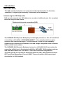
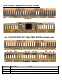
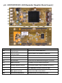
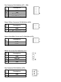
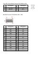
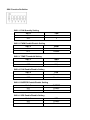
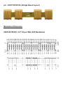
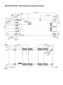
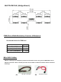
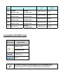
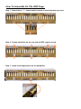
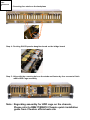
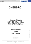
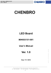
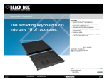
CHENBRO 2.5” 24-Port 6Gb/s SAS Expander Backplane 80H10341802A0 80H10341803A0 80H17341801A0 User’s Manual Version A0 March / 31 / 2011 Copyright Copyright © 2011 CHENBRO Micom Co., Ltd.. All rights reserved. Unless otherwise indicated, all materials in this manual are copyrighted by CHENBRO Micom Co., Ltd.. All rights reserved. No part of this manual, either text or image may be used for any purpose other than internal use within purchasing company. Therefore, reproduction, modification in any form or by any means, electronic, mechanical or otherwise, for reasons other than internal use, is strictly prohibited without prior written permission. CHENBRO Micom Co., Ltd. reserves the right to make improvement and modification to the products indicated in this manual at any time. Specifications are therefore subject to change without prior notice. Information provided in this manual is intended to be accurate and reliable. However, CHENBRO Micom Co., Ltd., assumes no responsibility for its use, nor for any infringements upon the rights of third parties, which may result from its use. Trademark All registered and unregistered trademarks and company names contained in this manual are property of their respective owners including, but not limited to the following. intel is trademark of intel Corporation. LSI is trademark of LSI Corporation. Adaptec is trademark of Adaptec Inc. Areca is trademark of Areca Technology Corporation. Technical Support CHENBRO works hard to offer our customers maximum performance from our chassis. But in case you have any problem with our product you can find supports from the following resources. Web Support Detail information of our products is in our website. You can find technical updates, installation guides, FAQs, technical specifications and more. Our web address is: www.chenbro.com. Email Support You can also fill out the technical support form at our Technical Support page. You technical issue inquiries will be sent directly to our support professionals. Phone Support You can also contact CHENBRO HQ or branch office for immediate support; their contact Information is as following: CHENBRO HQ CHENBRO Europe B.V. CHENBRO Micom (USA) Inc. Tel: 886-2-8226-5500 Tel: 31-40-295-2045 Tel: 1-909-947-3200 Fax: 886-2-8226-5423 Fax: 31-40-295-2044 Fax : 1-909-947-4300 Revision History Date April / 18 / 2011 Modifications First Release Safety Information Read the installation instructions before connecting to the power source. Only trained and qualified personnel should be allowed to install, replace or service this equipment. Never install this product in a wet environment. Position system cables and power cables carefully; route system cable and the power cable and plug so that they cannot be stepped on or tripped over. Be sure that nothing rests on your system component cables or power cable. Conventions Used in this Manual The following conventions are used in this manual. Note Icon: Provides more information on the current topic. Important Icon: Provides important information on the current topic that must not be overlooked. Introduction About this Guide The SAS expander backplane user’s manual provides the information for functions, capabilities, configuring and assembly / disassembly of this backplane. Introducing the SAS Expander SAS expander expands one SAS address to a number of additional ports. It is an optimal device for usage in data centers. Backplane The CHENBRO SAS Expander Backplane provides high performance, 24 x 2.5” disk drives connectivity and flexibility in RM235/RM418/RM417. It is a valuable solution to other expansive and complex topologies. The SAS expander is ideal for high availability, scalable server clustering environments, front-end storage subsystems used in clusters, SANs and NAS environments. The CHENBRO SAS Expander Backplane is based on LSI SAS2 X36 IC that enables the connection of 24 drives in directly attached SAS or SATA HDD. This Backplane performs SAS and SATA transfer rate at 6.0 Gb/s or 3 Gb/s with individual configurations. The SAS expander IC supports the Serial SCSI Protocol (SSP), SATA Tunneled Protocol (STP) and Serial Management Protocol (SMP). Those are based on SAS protocol and described in the SAS standard. Features General • To expand one Mini-SAS port (SFF-8087) to 24 x SATAII/SAS 2.5” HDD • Support HDD Failure / Activity Indication and HDD ID Mapping • Support RM235/RM418/RM417 only High-Speed I/O • 6.0 Gb/s or 3.0 Gb/s operations • Automatic negotiation of linking speed Application • SAS / SATA HDD NAS storage sever or enclosure • Security system • Video streaming / editing workstation SAS expander Backplane must be used only with SAS RAID card The supported HDD quantity is depended on the capability of the SAS RAID card in the system. Technical Specification This SAS Expander backplane assembly is including three boards : 80H10341802A0 ( 2.5” 24-port Mini SAS Backplane) Specification Host Interface Mini-SAS HDD Interface SAS Hot-Swap Yes, allows user to on line replace Hard Disk Drive Display LED indicates Hard Disk Drive status Power LED – Blue (When HDD is present) Access LED – Green (When HDD is busy) Error LED – Red (When HDD is error) Environment Monitor Temperature senor detect(RT1, RT2) Connectors 1.SAS29 *24 2.Mini-SAS Connector for bridge *8 3.Standard 4P Power connector *6 for +5V, +12V from power supply Dimension 419(L) x 81.2(W) x 2.4(H) mm Material FR4 6 layer 80H10341803A0 ( SAS Expander Daughter Board ) Specification SAS Expander Chip LSI SAS2 X36 ( 36 ports ) Cooling Four Fan connectors Connectors 1. Mini-SAS Connector for bridge *8 2. Mini-SAS Connector for RAID card *1 3. Mini-SAS Connector for Cable Link *1 4. Pin Header 2.54mm (2x3) *1, (1x4) *1 5. Wafer 2.54mm Connector 2P *2 6. Wafer 2.5mm Connector 2P *1 Dimension 170(L) x 75(W) x 1.6(H) mm Material FR4 8 layer 80H17341801A0 ( SAS Expander Bridge Board ) Specification Dimension 95.6(L) x 19.66(W) x 1.0(H) mm Material FR4 4 layer Accommodation Chassis RM235XX RM417XX RM418XX SAS Expander Backplane Assembly Outlook HDD Side Host Side p/n : 80H10341802A0 (2.5” 24-port Mini SAS Backplane Layout) JP1 JP2 JP3 CN011 CE1 CE2 CE3 CE4 CE5 CE6 CE7 CE8 CN241 JP4 JP5 Components Description Function JP1 ~ JP6 DC in, 4-Pin connector For backplane power source from power supply CE1 ~ CE8 CN011 ~ CN241 bridge board connecter Connection for SAS Expander daughter board SATAII / SAS HDD connecter Connect to 22pin SATAII or 29pin SAS 2.5” HDD JP6 p/n : 80H10341803A0 ( SAS Expander Daughter Board Layout ) JF5 JF1 SW1 JF2 CB1 JF3 JF4 JC4 CB2 JC5 JC3 JC8 Components CB1 CB2 CE5 CE6 CE1 CE2 Description Mini-SAS SFF-8087 Connector – Internal Input Mini-SAS SFF-8087 Connector – Internal Output CE7 CE3 JC1 CE8 CE4 Function Internal input from SAS RAID Card Internal output to rear window for expansion CE1~CE8 Bridge Board Connector Connection For Backplane JF1~JF4 FAN connecter 4x Four Pin Connecter With PWM Function JF5 Fan Connector Power Source For Heat Sink Cooling Fan ( not used ) JC1 RS232 Connector For Debug ( only for Chenbro Technician ) JC3 Firmware Upload Connector For Firmware Update ( only for Chenbro Technician ) JC4, JC5 Alarm、Mute Connecter JC8 SW1 Chassis Failure LED And Alarm Mute Signal Connector DIP Switch (for FAN and Temperature) JC4 = PSU Alarm connecter (connect to PSU) JC5 = PSU Mute connecter (connect to PSU) Send Chassis Failure LED And Alarm Mute Signal To Chassis Front LED / Control Board Set FAN Function and Temperature Level Fan Connector Pin Definition (JF1 ~ JF4) Pin NO. Descriptions 1 GND 2 12V 3 FAN Clock Input 4 FAN PWM Output Power Failure Connector Pin Definition (JC4) Pin NO. Descriptions 1 GND 2 Fail signal Input(Active Low) Power Alarm Mute Connector Pin Definition (JC5) Pin NO. Descriptions 1 MUTE - 2 MUTE + RS232 Connector Pin Definition (JC1) Pin NO. Descriptions 1 GND 2 KEY PIN 3 RXD 4 TXD Fan Connector Pin Definition (JF5) Pin NO. Descriptions 1 GND 2 12V Front LED / Control Board Connector Pin Definition (JC8) Pin NO. Descriptions Pin NO. Descriptions 1 FAIL LED + 2 FAIL LED - 3 KEY PIN 4 NC 5 MUTE SW + 6 MUTE SW - Mini SAS Connector Pin Definition (CB1 ~ CB2) Pin NO. Descriptions Pin NO. Descriptions A1 GND B1 GND A2 RP1 B2 TP1 A3 RN1 B3 TN1 A4 GND B4 GND A5 RP2 B5 TP2 A6 RN2 B6 TN2 A7 GND B7 GND A8 NC B8 NC A9 NC B9 NC A10 NC B10 NC A11 NC B11 NC A12 GND B12 GND A13 RP3 B13 TP3 A14 RN3 B14 TN3 A15 GND B15 GND A16 RP4 B16 TP4 A17 RN4 B17 TN4 A18 GND B18 GND SW1 Function Definition SW1-1: FAN Quantity Setting Sw1-1 FAN ON 4 OFF 3 SW1-2: PWM Enable/Disable Setting Sw1-2 PWM ON Enable OFF Disable SW1-3: TEMP Threshold Setting Sw1-3 ON TEMP 65℃ OFF 55℃ SW1-4: FAN Enable/Disable Setting Sw1-4 FAN ON Enable OFF Disable SW1-5: BUZZER Enable/Disable Setting Sw1-5 BUZZER ON Enable OFF Disable SW1-6: SES Enable/Disable Setting Sw1-6 SES ON Enable OFF Disable p/n : 80H17341801A0 ( Bridge Board Layout ) Mechanical Dimension 80H10341802A0 ( 2.5” 24-port Mini SAS Backplane) 80H10341803A0 ( SAS Expander Daughter Board 80H17341801A0 ( Bridge Board ) PWM (Pulse Width Modulation) Function of Backplane See the table below for PWM level Duty Cycle Under 45℃ (113℉) 50% 45℃~50℃ (113℉~122℉) 85% 50℃ (122℉) and above 100% Mini-SAS Cables RM23212 SAS Expander Backplane provides most benefits to users using various SAS RAID card via different conversion cables. Chenbro provides various cables for different interfaces which include the followings: (A) (B) Connector Cable Type A1 A2 A3 A4 B P/N Host (RAID Card) Side Mini-SAS Mini-SAS (SFF-8087 36pin) (SFF-8087 36pin) Mini-SAS Mini-SAS (SFF-8087 36pin) (SFF-8087 36pin) Mini-SAS Mini-SAS (SFF-8087 36pin) (SFF-8087 36pin) Mini-SAS Mini-SAS (SFF-8087 36pin) (SFF-8087 36pin) SATA-7Pin x4 Length Backplane Side Mini-SAS (SFF-8087 36pin) 26H113215-027 200 mm 26H113215-028 350 mm 26H113215-029 500 mm 26H113215-030 600 mm 26H113215-010 600 mm Compatible SAS RAID Cards Manufacture Model Number 3Wware 9750-8I MegaRAID 9260-8I 1680DI-IX20-16 52445 The maximum quantity of supported physical drives per SAS RAID Card is depended on the capability of the SAS RAID card in the system. Refer to the technical document or user guide provided by RAID card manufacturer. How To Assemble On The HDD Cage Step 1 : Attach three “ L “ shape metal brackets on the backplane by screw Step 2 : Fasten backplane on the rear side of HDD cage by screw Step 3 : Insert two bridge boards on the backplane HDD LED Cable: 26H113215-0 05 Step 4 : Screwing four studs on the backplane Step 4 : Ducking SAS Expander daughter board on the bridge board Step 5 : Align with the screwing hole on the studs and fasten by four screws to finish whole HDD Cage assembly Note : Regarding assembly for HDD cage on the chassis , Please refer to RM417/RM418 Chassis quick installation guide from Chenbro official web site