1
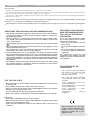
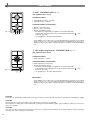
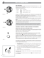
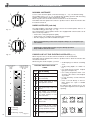
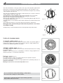
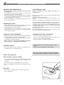
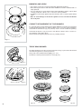
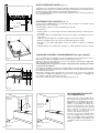
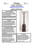
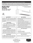
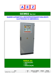
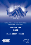
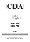
HCG301 Domino Two Burner
Gas Hobs
Manual for Installation, Use and Maintenance
Passionate about style
Customer Care Department • The
Group Ltd. • Harby Road • Langar • Nottinghamshire • NG13 9HY
T : 01949 862 012 F : 01949 862 003 E : [email protected] W : www.cda.eu
ENGLISH
Instructions for use
Dear Customer,
Thank you for having purchased and given your preference to our product.
The safety precautions and recommendations reported below are for your own safety and that of others. They will also provide a
means by which to make full use of the features offered by your appliance.
Please preserve this booklet carefully. It may be useful in future, either to yourself or to others in the event that doubts should arise
relating to its operation.
This appliance must be used only for the task it has explicitly been designed for, that is for cooking foodstuffs. Any other form
of usage is to be considered as inappropriate and therefore dangerous.
The manufacturer declines all responsibility in the event of damage caused by improper, incorrect or illogical use of the appliance.
IMPORTANT PRECAUTIONS AND RECOMMENDATIONS
✓ After having unpacked the appliance, check to ensure that it is not damaged.
If you have any doubts, do not use it and consult your supplier or a professionally qualified technician.
✓ Packing elements (i.e. plastic bags, polystyrene foam, nails, packing straps,
etc.) should not be left around within easy reach of children, as these may
cause serious injuries.
✓ The packaging material is recyclable and is marked with the recycling symbol
.
✓ Do not attempt to modify the technical characteristics of the appliance as this
may become dangerous to use.
✓ The manufacturer cannot be considered responsible for damage caused by
unreasonable, incorrect or rash use of the appliance.
✓ If you should decide not to use this appliance any longer (or decide to substitute an older model), before disposing of it, it is recommended that it be made
inoperative in an appropriate manner in accordance to health and environmental protection regulations, ensuring in particular that all potentially hazardous
parts be made harmless, especially in relation to children who could play with
old appliances.
✓ The appliance should be installed and all the gas/electrical connections made
by a qualified engineer in compliance with local regulations in force and following the manufacturer's instructions
IMPORTANT PRECAUTIONS
AND RECOMMENDATIONS
FOR USE OF ELECTRICAL
APPLIANCES
Use of any electrical appliance implies
the necessity to follow a series of fundamental rules. In particular:
✓ Never touch the appliance with wet
hands or feet;
✓ do not operate the appliance barefooted;
✓ do not allow children or disabled people to use the appliance without your
supervision.
The manufacturer cannot be held
responsible for any damages caused by
improper, incorrect or unreasonable use
of the appliance.
DECLARATION OF CE
CONFORMITY
– This cooking hob has been designed
to be used only for cooking. Any other
use (such as heating a room) is
improper and dangerous.
TIPS FOR THE USER
✓ During and after use of the cooktop, certain parts will become very hot. Do not
touch hot parts.
✓ Keep children away from the cooking hob when it is in use.
✓ After use, ensure that the knobs are in position ● (off), and close the main gas
delivery valve or the gas cylinder valve.
✓ In case of difficulty in the gas taps operation, call Service.
✓ Before any cleaning or maintenance, switch off the electricity to the cooktop.
– This cooking hob has been designed,
constructed, and marketed in compliance with:
-Safety requirements of the "Gas"
Directive 90/396/EEC;
-Safety requirements of “Low voltage”
Directive 2006/95/EC;
-Safety requirements of “EMC”
Directive 89/336/EEC;
-Requirements
of
Directive
93/68/EEC.
Risk of fire!
✓ Do not leave inflammable material on the cooktop.
✓ Make sure that the electrical cables of other appliances installed nearby cannot
come into contact with the cooktop.
✓ Never cook the food directly on the electric hotplates, but in special pans or
containers.
These instructions are only valid
for the countries indicated by the
symbols on the cover of the
instruction booklet and on the
appliance itself.
21
1
FEATURES
“2 GAS” COOKING HOB (Fig. 1.1)
2
The appliance has class 3
COOKING POINTS
1. Semirapid burner (SR) - 1,75 kW
2. Rapid burner (R) - 3,00 kW
CONTROL PANEL DESCRIPTION
1
Fig. 1.1
4
5
3
3. Burner 2 (R) control knob
4. Burner 1 (SR) control knob
5. Electric gas-lighting device;
if the device is not installed, the appliance may be provided with:
- A gas-lighter incorporated into the knob (★ symbol beside flame
heat/max. gas flow).
- No gas-lighter (no ★ symbol beside knobs).
- max.
✓ If the appliance has a safety valve system fitted (beside every burner is a T-shaped
probe, as in Fig. 5.2 - not to be confused with the S-shaped electrode of the gaslighter), the flow of gas will be stopped if and when the flame should accidentally go
out.
“1 GAS triple ring burner” COOKING HOB (Fig. 1.2)
The appliance has class 3
1
COOKING POINTS
1. Triple ring burner - 3,50 kW
CONTROL PANEL DESCRIPTION
Fig. 1.2
3
2
2. Triple ring burner control knob
3. Electric gas-lighting device;
if the device is not installed, the appliance may be provided with:
- A gas-lighter incorporated into the knob (★ symbol beside flame
heat/max. gas flow).
- No gas-lighter (no ★ symbol beside knobs).
- max.
Important Note:
✓ If the appliance has a safety valve system fitted (beside every burner is a T-shaped
probe, as in Fig. 5.2 - not to be confused with the S-shaped electrode of the gaslighter), the flow of gas will be stopped if and when the flame should accidentally go
out.
CAUTION:
If the burner is accidentally extinguished, turn the gas off at the control knob and wait at least 1 minute before attempting to relight.
CAUTION:
Gas hobs produce heat and humidity in the environment in which they are installed.
Ensure that the cooking area is well ventilated by opening the natural ventilation grilles or by installing an extractor hood connected to an outlet duct.
CAUTION:
If the hob is used for a prolonged time it may be necessary to provide further ventilation by opening a window or by increasing the
suction power of the extractor hood (if fitted).
22
“2 ELECTRIC” COOKING HOB
(Fig. 1.3)
- Electrical isulation Class I.
- Overheating surfaces protection Type Y.
2
COOKING POINTS
1. Electrical plate Ø 145 - (1000 W - 1500 W)
2. Electrical plate Ø 180 - (1500 W - 2000 W)
1
CONTROL PANEL DESCRIPTION
3. Electrical plate 1 control knob
4. Electrical plate 2 control knob
5. Power indicator light
Fig. 1.3
3
5
4
VITROCERAMIC HOBS (Fig. 1.4, 1.5, 1.6, 1.7)
- Electrical isulation Class I.
- Overheating surfaces protection Type Y.
2
SCHOTT
COOKING POINTS
1.
2.
3.
4.
5.
3 circuits cooking zone Ø 145 - 1200 W
3 circuits cooking zone Ø 180 - 1700 W
Hi-light cooking zone Ø 145 - 1200 W
Hi-light cooking zone Ø 180 - 1800 W
Halogen cooking zone Ø 180 - 1800 W
1
0
0
1
1
6
5
2
3
6
5
2
4
3
Fig. 1.4
4
CONTROL PANEL DESCRIPTION
10
7
7. Front zone control knob
8. Rear zone control knob
10. Front zone residual heat indicator
11. Rear zone residual heat indicator
12. Power indicator light
12
11
8
4
SCHOTT
3
0
9
7
6
10
9
5
2
3
7
12
5
6
11
0
0
1
5
10
6
12 11
9
Fig. 1.6
4
7
5
8
7
6
10
9
2
3
7
12
Fig. 1.7
4
8
5
10
1
11
2
3
4
8
7
0
1
10
3
9
8
7
0
11
2
10
5
4
3
1
11
6
3
8
SCHOTT
1
2
Fig. 1.5
4
8
5
10
7
1
11
2
3
4
8
SCHOTT
0
1
11
10
6
5
11
8
23
2
GAS COOKING HOBS
GAS BURNERS
Gas flow to the burners is adjusted by turning the knobs (illustrated in figs. 2.1a - 2.1b)
which control the safety valves.
Turning the knob so that the indicator line points to the symbols printed on the panel
achieves the following functions:
✓ full circle
Fig. 2.1a
● = closed valve
✓ symbol
= maximum aperture or flow
✓ symbol
= minimum aperture or flow
To light one of the gas burners, hold a flame (e.g. a match) close to the top part of the
burner, push in and turn the relative knob in an anti-clockwise direction, pointing the
knob indicator towards the large flame symbol (i.e. max. gas flow).
To reduce the gas flow to minimum, rotate the knob further anti-clockwise to point the
indicator towards the small flame symbol.
The maximum aperture position permits rapid boiling of liquids, whereas the minimum
aperture position allows slower warming of food or maintaining boiling conditions of
liquids.
Other intermediate operating adjustments can be achieved by positioning the
indicator between the maximum and minimum aperture positions, and never between
the maximum aperture and closed positions.
N.B. When the cooker top is not being used, set the gas knobs to their closed positions and also close the cock valve on the gas bottle or the main gas supply line.
Fig. 2.1b
VALVELESS ELECTRIC SPARK-LIGHTING GAS BURNERS
Models fitted with electric spark lighter button
On these cooker tops, to light one of the burners you have to push in and turn the relative knob to the maximum aperture position (large flame symbol) and press the electric
lighter button (fig. 2.2) until the flame has been lit.
Adjust the gas valve to the desired position.
Models fitted with electric lighter incorporated into the burner knobs
★ symbol beside the
symbol (max. heat/max. gas flow) (fig. 2.1b).
To light one of the gas burners, push in and turn the relative knob to the maximum
aperture position (large flame symbol) and hold the knob in until the flame has been lit.
The sparks produced by the lighter situated inside the relative burner will light the
flame.
In the event that the local gas supply conditions makes it difficult to light the burner in
maximum aperture position, try again with the knob in minimum position.
Fig. 2.2
LIGHTING GAS BURNERS FITTED WITH SAFETY VALVE DEVICE
In order to light the burner, you must:
1 – Turn the knob in an anti-clockwise direction up to the maximum aperture, push in
and hold the knob;
In models with the gas lighter incorporated in the knob, this will light the gas. If
there is no mains electrical supply, bring a lighted match close to the burner.
2 – For models with push-button lighting only: push the gas-lighter button.
3 – Wait about ten seconds after the gaslights before releasing the knob (starting time
for the valve).
4 – Adjust the gas valve to the desired position.
If the burner flame should go out for some reason, the safety valve will automatically
stop the gas flow.
To re-light the burner, return the knob to the closed ● position and repeat the operations for lighting.
24
Fig. 2.3
CHOICE OF BURNER
DIAMETERS OF PANS WHICH MAY BE USED
ON THE HOBS
(fig. 2.4)
The symbols printed on the panel beside the gas knobs indicate the correspondence
between the knob and the burner.
The most suitable burner is to be chosen according to the diameter and volume capacity of the container to be warmed.
It is important that the diameter of the pots or pans suitably match the heating potential of the burners in order not to jeopardise the efficiency of the burners, bringing about
a waste of gas fuel.
A small diameter pot or pan placed on a large burner does not necessarily mean that
boiling conditions are reached quicker.
BURNERS
MINIMUM
MAX.
Semirapid
12 cm
22 cm
Rapid
22 cm
26 cm
Triple ring
24 cm
28 cm
Maximum diameter for woks: 36 cm.
do not use pans with concave or convex bases
Caution!
the cooking hob becomes very hot during operation.
Keep children well out of reach.
Fig. 2.4
GRATE FOR SMALL PANS (optional)
- (See fig. 2.5)
This grate is to be placed on top of the (smaller) semirapid burner when using small
diameter pans, in order to prevent them from tipping over.
Fig. 2.5
SPECIAL WOK GRILLE (optional)
(fig. 2.6 e 2.7).
This special grille for woks should be placed over the pan-rest for the largest burner.
Warning:
✓ Using woks without this special grille may cause the burner to malfunction.
✓ Do not use the grille for ordinary, flat-bottomed saucepans.
WRONG
Fig.
2.6
CORRECT
Fig.
2.7
25
3
ELECTRIC COOKING HOBS
NORMAL HOTPLATE
0
1
6
5
2
3
RAPID HOTPLATE (red dot)
4
The rapid hotplate control knob is similar to that of the normal hotplate, with 6 or 12
selectable heating positions (fig. 3.1 - 3.2).
The characteristics of this hotplate, which is also equipped with a thermostatic cut-off
device, make it possible to:
– achieve the cooking temperature rapidly
– make full use of its output power using flat-bottomed pans
– limit the output power with unsuitable saucepans.
Fig. 3.1
0
1
12
11
2
10
3
4
9
8
7
6
To turn on the electric hotplate, rotate the knob (fig. 3.1 - 3.2) o the desired setting.
The numbers from 1 to 6 or 1 to 12 indicate the operating positions with increasing
number corresponding to higher temperature settings.
When the pan comes to the boil, turn the heat down to the level desired.
Remember that the hotplate will continue to produce heat for about five minutes after
it has been turned off.
Never cook food directly on the electric hotplates! Always use a saucepan or special container.
Caution! the cooking hob becomes very hot during operation.
Keep children well out of reach.
5
PROPER USE OF THE ELECTRIC HOTPLATE
Fig. 3.2
Hob controlled by
7-position
switch
Hob controlled by
continuous energy
regulation switch
0-6
0 - 12
1
1
2
3
2
4
5
3
6
7
4
When the pan comes to the boil, turn the heat down to the level desired.
Remember that the hotplate will continue to produce heat for about five minutes after
it has been turned off.
While using the electric hotplate, you must:
✓ avoid keeping it on without something
on it;
ELECTRIC HOTPLATE USAGE
✓ avoid pouring liquids on it while it is
TABLE
hot;
✓ use flat-bottomed (electric hotplate
Position
type) pots and pans only
of switch Type of cooking
✓ use cooking receptacles which cover
0 0 Switched OFF
as much of the surface of the hotplate
as possible.
1 1 For melting operations (of but✓ to save electricity, use lids whenever
2 2 ter or chocolate)
possible.
✓ never cook food directly on the hot2 To keep foods warm or heat
plate: always use a pan or suitable
2 3 small quantities of water.
container.
4
An indicator light located close to the
4 To heat greater quantities of
control panel signals that the hotplate is
3 5 water and to whip creams and
operating.
6 sauces.
8
9
5
3
4
6
7
Slow boiling, e.g. spaghetti,
soups, boiled meats, to continue steam heating of roast
meats and stews.
4
7
8
For all kinds of fried foods,
steaks, cutlets and cooking
without a lid.
4
5
8 For browning of meat, cooked
9 potatoes, fried fish and for boi10 ling large quantities of water.
10
11
6
12
= Warming
= Cooking
= Roasting - Frying
26
Fig. 3.4
(fig. 3.3)
6 11 Rapid frying, grilled steaks, etc.
12
Fig. 3.3
4
VITROCERAMIC HOBS
The main characteristic of this pyroceram cooker top is that it permits rapid vertical
transmission of the heat from the heating elements below to the saucepans on top.
0
1
The heat does not spread horizontally, however, and therefore the glass stays cold only
a few centimetres from the hob.
The hobs are controlled by the 7 positions switch (0÷6) (fig. 4.1) or by the continuous
energy regulation switch (0÷12) (fig. 4.2).
The heat intensity can be regulated continuously from 0 (off) to “6” or “12” (max).
Check that the hob is clean and then switch on by turning the control knob.
When the top is working, the pilot light will be on.
When the hob temperature is above 60°C, the corresponding indicator light will come
on to indicate that the hob is hot.
This light will stay on even after the hob has been switched off to indicate that the hob
is still hot.
The residual heat persists for some time after the hob has been switched off.
During this time avoid touching the hob and take particular care if there
are children nearby.
The light will go out automatically when the hob temperature drops below 60°C.
6
5
2
3
Fig. 4.1
4
0
1
12
11
2
10
3
4
9
8
Fig. 4.2
7
6
5
TYPES OF COOKING AREA
“3 circuiti” radiant zones
(Fig. 4.3)
The heating element consists of 3 electrical resistances which can operate together or
separately according to the setting of the 7-position switch or energy regulator 0-12.
It reaches the required temperature very quickly.
“Hi-light” radiant zones
(Fig. 4.4)
The heating element is formed of a coil of resistant material which reaches the working
temperature quickly.
Operation of the cooking zone is controlled by a continuous energy regulator from 1
(minimum position) to 12 (maximum temperature).
Halogen zones
Fig. 4.3
(Fig. 4.5)
The heating element consists of 2 halogen lamps and an electrical resistance.
It instantly reaches the required temperature.
The area is controlled by a continuous energy regulator from 1 (minimum position) to 12
(maximum temperature).
Warning for eyes: Do not stare at the lamp when it is on.
Fig. 4.4
Do not scratch the cooktop with cutting or sharp objects.
Do not use the cooktop as a work surface.
Caution! the cooking hob becomes very hot during operation.
Keep children well out of reach.
Fig. 4.5
27
Hob controlled by
7-position
switch
Hob controlled by
continuous energy
regulation switch
0-6
0 - 12
1
1
2
3
2
3
HINTS FOR SAFE USE OF THE HOBS
– Before switching on, check which knob controls the required hob. You are advised to
place the saucepan on the hob before switching on and to take it off after switching
off.
– Use saucepans with an even flat bottom (be careful of cast iron saucepans). Uneven
bottoms can scratch the pyroceram surface. Check that the bottom is clean and dry.
4
– Check that the saucepan handle does not protrude from the top to avoid knocking it
over. This precaution also makes it more difficult for children to reach the saucepan.
5
– Do not use the top if the surface is broken or damaged.
6
– Do not bend over the hobs when they are on.
7
– Do not leave aluminium foil, greaseproof paper etc. or plastic on the hob when it is
hot.
4
8
9
5
6
10
– Scrupulously follow the cleaning instructions.
11
– Do not drop heavy or sharp objects on the glass ceramic cooktop.
12
– If you note a crack in the cooktop, switch the appliance off immediately and call the
After-Sales Service.
= Warming
– If the cooktop has halogen lamps, do not stare at them.
= Cooking
– Never cook the food directly on the glass ceramic cooktop, but in special pans or
containers.
= Roasting - Frying
Fig. 4.6
ELECTRIC HOTPLATE USAGE
TABLE
Position
of switch
Type of cooking
0
0
Switched OFF
1
2
1
2
For melting operations (of butter or chocolate)
2
2 To keep foods warm or heat
3 small quantities of water.
4
3
4
5
6
To heat greater quantities of
water and to whip creams and
sauces.
3
4
6
7
Slow boiling, e.g. spaghetti,
soups, boiled meats, to continue steam heating of roast
meats and stews.
4
7
8
For all kinds of fried foods,
steaks, cutlets and cooking
without a lid.
4
5
8 For browning of meat, cooked
9 potatoes, fried fish and for boi10 ling large quantities of water.
6 11 Rapid frying, grilled steaks, etc.
12
28
– Remember that the hobs stay hot for quite a long time (approx. 30 min.) after they
have been switched off.
5
CLEANING AND MAINTENANCE
GENERAL RECOMANDATION
VITROCERAMIC HOB
✓ Before you begin cleaning you must ensure that the hob
is switched off.
It is advisable to clean when the appliance is cold and especially when cleaning the enamelled parts.
✓ All enamelled surfaces have to be washed with soapy water
or some other non-abrasive product with a sponge and are to
be dried preferably with a soft cloth.
✓ Avoid leaving alkaline or acid substances (lemon juice, vinegar etc.) on the surfaces.
Before cleaning the top, make sure that it is
switched off.
ENAMELLED PARTS
✓ All the enamelled parts must be cleaned with a sponge and
soapy water only or other non-abrasive products.
✓ Dry preferably with a chamois leather.
If acid substances such as lemon juice, tomato conserve,
vinegar etc. are left on the enamel for a long time they will
etch it, making it opaque.
Remove any encrustation using a special scraper which can be
bought (fig. 5.1).
Remove dust using a damp cloth.
Detergents can be used as long as they are not abrasive or corrosive.
All residues of detergent must be eliminated with a damp cloth.
Keep all objects that could be melted by the heat away from the
top: plastic objects, aluminium foil, sugar or sugary products.
If an object melts on the top, remove immediately (while the top
is still hot) using the special scraper to avoid permanent damage
to the pyroceram surface.
Avoid using knives and pointed objects as they could damage
the surface of the top.
Also avoid using abrasive sponges or wire wool which can permanently scratch the pyroceram surface.
STAINLESS STEEL ELEMENTS
CLEANING ELECTRIC HOTPLATES
✓ Stainless steel parts must be rinsed with water and dried with
a soft and clean cloth or with a chamois leather.
✓ For difficult dirt, usea specific non-abrasive product available
commercially or a little hot vinegar.
✓ Note: regular use could cause discolouring around the
burners, because of the high flame temperature.
✓ Always clean when the hotplate is tepid.
✓ Use a soft cloth, dampened with water, and a little salt. To
finish off, use a soft cloth with a little oil.
✓ Do not use water, to avoid the formation of rust.
CONTROL KNOB
✓ The control knobs may be removed for cleaning but care
should be taken not to damage the seal.
Do not scratch the cooktop with cutting or sharp
objects.
Do not use the cooktop as a work surface.
Do not use steam jet cleaners because the humidity
could infiltrate into the appliance making it dangerous.
GLASS LID (optional)
Electric plates and gas models
✓ Do not close the glass lid when the electrical plates are still
hot and when the oven, installed below the cooking hob is on
or still hot.
✓ Do not rest hot pans or heavy objects on the cooker lid.
✓ Remove any spillages from the surface of the lid before opening.
GAS TAPS
✓ In the event of operating faults in the gas taps, call the
Service Department.
Fig. 5.1
29
BURNERS AND GRIDS
✓ These parts can be removed and cleaned with appropriate products.
✓ After cleaning, the burners and their flame distributors must be well dried and correctly replaced.
✓ It is very important to check that the burner flame distributor and the cap has been
correctly positioned - failure to do so can cause serious problems.
✓ In appliances with electric ignition keep the electrode clean so that the sparks always
strike.
✓ Note: To avoid damage to the electric ignition do not use it when the burners
are not in place.
C
F
CORRECT REPLACEMENT OF THE BURNERS
T
S
It is very important to check that the burner flame distributor F and the cap C has been
correctly positioned (see figs. 5.2 and 5.6 ) failure to do so can cause serious problems.
Check that the electrode “S” (fig. 5.2) is always clean to ensure trouble-free sparking.
Check that the probe “T” (fig. 5.2) next to each burner is always clean to ensure correct operation of the safety valves.
Both the probe and ignition plug must be very carefully cleaned.
Fig. 5.2
TRIPLE RING BURNER
The triple ring burner must be correctly positioned (see fig. 5.3); the burner rib must be
enter in their logement as shown by the arrow.
Then position the cap A and the ring B (fig. 5.4 - 5.5).
The burner correctly positioned must not rotate (fig. 5.4).
Fig. 5.3
A
B
Fig. 5.4
30
Fig. 5.5
Fig. 5.6
Installation advice
6
INSTALLATION
IMPORTANT
– The appliance should be installed, regulated and adapted to
function with other types of gas by a QUALIFIED INSTALLATION TECHNICIAN.
Failure to comply with this condition will render the guarantee invalid.
– The appliance must be installed in compliance with regulations in force.
– Installation technicians must comply to current laws in force
concerning ventilation and the evacuation of exhaust gases.
– Always unplug the appliance before carrying out any maintenance operations or repairs.
✓ The appliance must be housed in heat-resistant units.
✓ These tops are designed to be embedded into kitchen
fixtures measuring 600 mm in depth.
✓ The walls of the units must not be higher than work top
and must be capable of resisting temperatures of 75
°C above room temperature.
✓ Do not instal the appliance near inflammable materials
(eg. curtains).
GAS COOKING HOBS
510
288
30
30
510
288
50
50
490
490
+0
–2
0
27
+0 2
–
Fig. 6.1a
+
– 20
0
27
+0 2
–
Fig. 6.1b
TECHNICAL INFORMATION FOR THE INSTALLER
Before installing the cooktop, remove the protective film.
450 mm
In order to install the cooker top into the kitchen fixture, a hole with the dimensions
shown in figs. 6.1a - 6.1b has to be made, keeping in consideration the following:
– within the fixture, between the bottom side of the cooker top and the upper surface of any other appliance or internal shelf there must be a clearance of at least
30 mm;
– the cooker top must be kept no less than 100 mm away from any side wall;
– the cooker top must be kept at a distance of no less than 50 mm from the rear
wall.
– there must be a distance of at least 650 mm between the hob and any wall cupboard or extractor hood positioned immediately above (see fig. 6.2)
650 mm
This cooktop can be built into a working surface 20 to 40 mm thick and 600 mm
deep.
– the coatings of the walls of the unit or appliances near the cooktop must be heat
resistant ("Y" protection against heating in compliance with standards EN
60335-2-6).
Do not instal the appliance near inflammable materials (eg. curtains).
Fig. 6.2
31
;;;;;;;
@;
;@;@
;@;@
Fig. 6.3
30 mm
;;;;;
;
;;
;;;;;;;
Clearance
Cupboard
door
Space for
connections
A
A
A
A
WITH CUPBOARD DOORS
(fig. 6.3)
The fixture has to be made according to specific requirements in order to prevent the
gas burners from going out, even when the flame is turned down to minimum, due to
pressure changes while opening or closing the cupboard doors.
It is recommended that a 30 mm clearance be left between the cooker top and the fixture surface beneath it.
FASTENING THE COOKTOP
(fig. 6.4)
Each cooktop is supplied with a set of tabs and screws to fasten it on units with a working surface from 2 to 4 cm deep.
The kit includes 4 tabs “A” and 4 self-threading screws “B”.
✓ Cut the unit.
✓ Stretch gasket “C” over the edge of the hole made, being careful to overlay the junction edges.
✓ Turn the cooktop over and put tabs “A” into the mountings; only tighten screws “B”
a few turns.
Make sure that the tabs are mounted correctly as shown in the figure.
✓ Put the cooktop into the hole cut into the unit and position it correctly.
✓ Put tabs “A” into place and tighten screws “B” until the cooktop is completely
secured.
✓ Using a sharp tool cut off the part of gasket “C” which protrudes from the cooktop.
CHOOSING SUITABLE SURROUNDINGS (for gas models)
The room where the gas appliance is to be installed must have a natural flow of air so
that the gas can burn (in compliance with the current laws in force).
The flow of air must come directly from one or more openings made in the outside walls
with a free area of at least 100 cm2.
If the appliance does not have a no-flame safety device this opening must have
an area of at least 200 cm2.
The openings should be near the floor and preferably on the side opposite the exhaust
for combustion products and must be so made that they cannot be blocked from either
the outside or the outside.
When these openings cannot be made, the necessary air can come from an adjacent
room which is ventilated as required, as long as it is not a bedroom or a danger area
(in compliance with the current laws in force).
In this case, the kitchen door must allow the passage of the air.
Fig. 6.4
A
40 mm max.
B
20 mm min.
C
Fig. 6.5
Extractor hood for
products of
combustion
H min 650 mm
DISCHARGING PRODUCTS
OF COMBUSTION
Electric fan to
extract products of
combustion
Air vent
32
Fig. 6.6
Air vent
Fig. 6.7
Extractor hoods connected directly to
the outside must be provided, to allow
the products of combustion in the gas
appliance to be discharged (fig. 6.6).
If this is not possible, an electric fan
may be used, attached to the external
wall or the window; the fan should
have a capacity to circulate air at an
hourly rate of 3-5 times the total
volume of the kitchen (fig. 6.7).
The fan can only be installed if the
room has suitable vents to allow air to
enter, as described under the heading
“Choosing suitable surroundings” (in
compliance with the current laws in
force).
ELECTRICAL PLATES AND VITROCERAMIC COOKING HOBS
288
510
288
30
510
50
50
490
490
+
– 20
0
27
+02
–
Fig. 6.8a
+
– 20
70
+02
–
2
Fig. 6.8b
TECHNICAL INFORMATION FOR THE
INSTALLER
Before installing the cooktop, remove the protective film.
650 mm
In order to install the cooker top into the kitchen fixture, a hole
with the dimensions shown in figs. 6.8a and 6.8b has to be
made, keeping in consideration the following:
– within the fixture, between the bottom side of the cooker top
and the upper surface of any other appliance or internal shelf
there must be a clearance of at least 30 mm;
– the cooker top must be kept no less than 50 mm away from
any side wall;
– the cooker top must be kept at a distance of no less than 50
mm from the rear wall.
– there must be a distance of at least 650 mm between the hob
and any wall cupboard or extractor hood positioned immediately above (see figs. 6.9a and 6.9b).
– the coatings of the walls of the unit or appliances near the
cooktop must be heat resistant ("Y" protection against heating in compliance with standards EN 60335-2-6).
450 mm
These cooking hobs are designed to be embedded into kitchen
fixtures measuring 600 mm in depth and from 20 to 40 mm
thick, for 2 electrical plates hob, and from 30 to 40 mm thick for
vitroceramic hob.
50 mm
Fig. 6.9a
650 mm
450 mm
Do not instal the appliance near inflammable materials (eg.
curtains).
50 mm
Fig. 6.9b
33
FASTENING THE COOKTOP
A
A
Each cooker top is provided with an installation kit including brackets and screws for
fastening the top to fixture panels from 20-30 to 40 mm thick, figs. 6.11 (2 electrical
plates hob) e 6.12 (vitroceramic hob).
✓ Cut the unit.
A
A
✓ Stretch gasket “D” over the edge of the hole made, being careful to overlay the junction edges
✓ Turn the cooktop over and put tabs “A” (fig. 6.10) into the mountings, only tighten
screws “B” a few turns.
Make sure that the tabs are mounted correctly as shown in the figures 6.11 and 6.12.
Turn the tabs so that the cooktop can be put into the hole.
✓ Put the cooktop into the hole cut into the unit and position it correctly.
Fig. 6.10
✓ Put tabs “A”; into place, tooth “C” of the tabs should go into the hole.
✓ Tighten screws “B” until the cooktop is completely secured.
✓ Using a sharp tool cut off the part of gasket “D” which protrudes from the cooktop.
40 mm max.
A
40 mm max.
B
20 mm min.
D
30 mm min.
C
Fig. 6.11
C
D
B
Fig. 6.12
34
A
7
GAS SECTION
GAS CONNECTIONS
C
Make sure that the hob is adapted to function with the type of gas supply available (see
label). If not, refer to the section headed “Adapting the appliance to function with different types of gas”.
F
GASES
1/2” G
The gases used for the operation of cooking appliances may be grouped by their characteristics into two types:
– Liquid gas: Butane gas (G 30) and Propane gas (G 31)
– Natural gas (G 20)
F
G
1/2" G
conical
Connecting to gas mains:
GB
Cat:
A
Fig. 7.1
II 2H3+
The cooktop connection (fig. 7.1a - 7.1b) is made up as follows:
✓ 1 nipple "A"
✓ 1 union elbow "C"
✓ gaskets “F”
✓ 1 conical elbow “G”
Connection to the gas main must be performed by a qualified technician, in compliance
with the current laws in force.
Before connecting the appliance to the gas main, mount conical elbow “G” (supplied
with appliance) onto the union elbow “C,” upon which the gasket “F” has been placed.
To maintain the thickness of 3 cm, the hob is fitted with a channel to contain the connection pipe.
Fig. 7.2
The gas inlet union can be turned in the direction required after the union elbow C - nipple A connection has been slackened (Fig. 7.2).
Never put it in the horizontal or vertical position.
IMPORTANT:
✓ Never turn union C using force without first slackening nut A.
✓ Gaskets F (Fig. 7.1) guarantee the seal of the gas connection.
Replace them whenever they are even slightly deformed or imperfect.
✓ Any connection to fixed metal pipes must be done in such a way so as not to place undue stress on the hob chassis.
✓ If using flexible metal pipes, make sure they are not squashed, and do not come into contact with moving parts.
✓ Any flexible pipes must be so installed as to be easily inspected along their whole length. They must be changed before the expiry
date (printed on the pipe itself) and not exceed 2 metres in length.
✓ After connecting to the gas mains, check that the couplings are correctly sealed, using soapy solution, but never a naked flame.
ADAPTING THE APPLIANCE TO FUNCTION WITH DIFFERENT TYPES OF GAS
If a gas different from that indicated on the label is used, adapt the cooktop to this new function.
Every cooking hob is provided with a set of injectors for the various types of gas.
Injectors not supplied can be obtained from the After-Sales Service.
Select the injectors to be replaced according to the table below.
The nozzle diameters, expressed in hundredths of a millimetre, are marked on the body of each injector.
35
INJECTORS TABLE
GB
Cat: II 2H3+
NOMINAL
POWER
REDUCED
POWER
G30/G31
28-30/37 mbar
G20
20 mbar
BURNERS
[Hs - kW]
[Hs - kW]
Ø injector
[1/100 mm]
Ø injector
[1/100 mm]
1,75
0,45
65
97
Semi-rapid (SR)
Rapid (R)
3,00
0,75
85
115
Triple ring (TR)
3,50
1,50
95
135
OPERATIONS TO BE PERFORMED WHEN SUBSTITUTING
THE INJECTORS
J
✓ Remove the gratings, the burner covers and the knobs;
✓ Using a wrench substitute the nozzle injectors “J” (Fig. 7.3 - 7.4) with those most
suitable for the kind of gas for which it is to be used.
The burner are conceived in such a way so as not to require the regulation of the
primary air.
Fig. 7.3
REGULATING THE BURNER MINIMUM SETTING
When switching from one type of gas to another, the minimum flow rate must also be
correct: the flame should not go out even when passing suddenly from maximum to
minimum flame.
To regulate the flame follow the instructions below:
– Light the burner
– Set the cock valve to minimum
J
On gas valves provided with adjustment screw in the centre of the shaft (fig. 7.5):
– Using a screwdriver with max. diameter 3 mm, turn the screw inside the tap until the
correct setting is obtained.
On gas valves provided with adjustment screw on the valve body (fig. 7.6):
– Turn the screw “A” to the correct setting with a screwdriver.
For G 30/G 31 gas, tighten the adjustment screw completely.
Fig. 7.4
LUBRICATING THE GAS
TAPS
If one of the gas taps becomes difficult to
turn, dismantle it, thoroughly clean with
petrol and apply special high-temperature grease.
A
36
Fig. 7.5
Fig. 7.6
These operations must be performed by
a specialised engineer.
8
ELECTRICAL SECTION
IMPORTANT: Installation has to be carried out according
to the instructions provided by the manufacturer.
Incorrect installation might cause harm and damage to
people, animals or objects, for which the manufacturer
accepts no responsibility.
DETAILS
✓ Connection to the electric power supply must be carried out
by a qualified technician and following the appropriate safety
regulations;
✓ Before carrying out the connection to the power supply, the
voltage rating of the appliance (stamped on the appliance
identification plate) must be checked for correspondence to
the available mains supply voltage, and the mains electric
wiring should be capable of handling the cooker’s power rating (also indicated on the identification plate);
✓ The appliance is supplied without a power supply plug and
therefore if you are not connecting directly to the mains, a
standardized plug suitable for the load must be fitted.
A double pole switch must be provided no further than 2 metres
from the appliance to the electrical supply.
If you are using the hob for the first time, or after a period of disuse, you should set the controls to position 1 for approximately
30 seconds, to dry out any humidity.
This appliance must be connected by a competent person,
using fixed wiring via a DOUBLE POLE SWITCHED FUSED
SPUR OUTLET.
DOUBLE POLE SWITCHED
FUSED SPUR OUTLET
FUSE
ON
✓ The power point must be connected to a suitable earth wiring,
in conformity to current safety regulations.
✓ The colours of the wires in the hob power cable may not correspond with the colours marked on the terminals of your
electrical plug. The plug should in any case be wired as follows:
– connect the green/yellow wire to the terminal marked with
the letter PE or the earth symbol or coloured green/yellow;
– connect the blue wire to the terminal marked with the letter
N or coloured black;
– connect the brown wire to the terminal marked with the letter L or coloured red.
✓ It is possible to connect the appliance directly to the mains
supply by means of a heavy duty switch with 3 mm minimum
distance between the contacts.
✓ The power supply cord must not touch against any hot surfaces and must be placed so that its temperature does not
exceed 75°C at any point along its length.
USE A 3 AMP FUSE
for gas hobs use a 3 amp FUSE
for electric hobs use a 20 amp FUSE
We recommend that the appliance is connected by a qualified
electrician, who is a member of the N.l.C.E l C. and who will
comply with the l.E.E. and local regulations.
The wires in the mains lead are coloured in accordance with the
following code:
Green & Yellow = Earth
Blue = Neutral
Brown = Live.
As the colours of the wires in the mains lead for the appliance,
may not correspond with the coloured markings identifying the
terminals in your spur box, proceed as follows:
✓ After having installed the appliance, the power switch or
power plug must always be in a accessible position.
1) The wire which is coloured green and yellow must be connected to the terminal marked E (Earth) or
coloured
Green.
✓ The appliance must have its own supply; any other appliances
installed near it must be supplied separately.
2) The wire which is coloured blue must be connected to the terminal marked N (Neutral), or coloured Black.
– N.B. For connections to the mains power supply, never use
adaptors, reductions or multiple power points as these may
overheat and catch fire.
3) The wire which is coloured brown must be connected to the
terminal marked L (Live), or coloured Red.
In the event that installation should require modifications to the
mains supply wiring system, it is recommended that a qualified
technician be called to carry out substitution.
The technician will also have to verify that the cross-section of
the electric cables on the power point match the appliance’s
power rating.
Connection to a good earth wiring system is absolutely
essential.
The manufacturer accepts no responsibility for any inconvenience caused by failure to comply with this rule.
Before carrying out any work on the electrical section of
the appliance, it must be disconnected from the mains.
If the hob surface is cracked disconnect the appliance
from the mains.
37
REPAIRS
REPLACING THE POWER SUPPLY CABLE
(for 2 electrical plates and vitroceramic models)
Turn the cooktop over and unhook the terminal board cover by inserting a screwdriver
into the two hooks “A” (fig. 8.1).
Open the cable gland by unscrewing screw “F” (fig. 8.2), unscrew the terminal screws
and remove the cable.
The new supply cable, of suitable type and section, is connected to the terminal board
following the diagram fig. 8.3.
A
REPLACING THE POWER SUPPLY CABLE (for gas models)
- The supply cable must be replaced with a cable of the same type.
- The electrical cable must be connected to the terminal board following the diagrams of
fig. 8.4.
Fig. 8.1
F
FEEDER CABLE SECTION
COOKING HOB GAS
type “H05V2V2-F”
resistance to temperatures of 90°C
230 V~
3 x 0,75 mm2
Fig. 8.2
COOKING HOB ELECTRIC HOTPLATES
The external diameter of the supply cable must not be more than 9 mm.
tipo “H05RR-F”
230 V
230 V~
L1
N (L 2)
PE
COOKING HOB VITROCERAMIC
The external diameter of the supply cable must not be more than 9 mm.
type “H05RR-F”
Fig. 8.3
230 V~
230 V
L
Fig. 8.4
38
3 x 1,50 mm2
N
3 x 1,50 mm2
8
PARTE ELÉCTRICA
Importante: A instalação deve ser efetuada conforme as
instruções do fabricante.
Uma instalação erronea pode causar danos às pessoas,
animais ou coisas e defronte a tais acontecimentos o
fabricante não pode ser considerado responsável.
LIGAÇÃO À REDE ELÉCTRICA
✓ A ligação à rede eléctrica deve ser feita por técnicos qualificados e em conformidade com as normas vigentes.
✓ Antes de mais, é necessário verificar se a tensão de rede
corresponde ao valor indicado na chapa de características do
aparelho e se a secção dos cabos da instalação eléctrica tem
capacidade para suportar a carga indicada na mesma chapa.
✓ No caso do aparelho ser fornecido sem ficha, é necessário
montar uma ficha normalizada, adequada à potência absorvida pelo aparelho e conforme as normas locais vigentes.
✓ A ficha bipolar deve ser inserida numa tomada que esteja ligada ao sistema de terra conforme as normas de segurança.
✓ Dado que as cores dos núcleos do cabo de alimentação deste
aparelho podem não corresponder com as marcações coloridas que identificam os bornes da vossa tomada, proceder
como segue:
– O núcleo que é colorido de amarelo/verde deve ser conetado ao borne da tomada marcada com a letra PE ou com o
símbolo de terra ou colorido de verde ou amarelo/verde;
– O núcleo de cor azul deve ser conetado ao borne marcado
com a letra N ou colorido de preto;
– O núcleo colorado de marron deve ser conetado ao borne
marcado com a letra L ou colorida de vermelho;
✓ Pode-se fazer a ligação directa do aparelho à rede, colocando, entre o aparelho e a rede eléctrica, um interruptor omnipolar com abertura mínima entre os contactos de 3 mm.
✓ O cabo de alimentação não deve entrar em contacto com partes quentes e deverá ser colocado de maneira a não exceder,
em toda a sua extensão, a temperatura de 75°C.
✓ Depois do aparelho montado, o interruptor ou a tomada
devem estar sempre em posição acessível.
✓ O aparelho deve ser alimentado individualmente; outros eventuais aparelhos instalados nas proximidades devem ser alimentados separadamente.
– NOTA: Para a ligação à rede, não utilize adaptadores,
reduções ou caixas de derivação, porque podem provocar
um aquecimento excessivo ou queimaduras.
– Quando for constatada uma rachadura na superfície do
fogão, desligar o aparelho da rede.
Se, para a montagem do aparelho, for necessário fazer alterações à instalação eléctrica de casa ou no caso de incompatibilidade entre a tomada e a ficha do aparelho, contacte um técnico profissionalmente qualificado para proceder às substituições.
Este último deverá ainda, e nomeadamente, verificar se a
secção dos cabos da tomada é adequada à potência absorvida
pelo aparelho.
REPARAÇÕES
SUBSTITUIÇÃO DO CABO DE ALIMENTAÇÃO (mod.
placas eléctricas e placas vitroceramica)
Coloque a placa de cozedura com o fundo voltado para cima e
abra a tampa da caixa de terminais, inserindo uma chave de
parafusos nos dois engates “A” (fig. 8.1).
Abra o elemento de fixação do cabo, desapertando o parafuso
“F” (fig. 8.2). Desaperte os parafusos dos terminais e retire o
cabo.
O novo cabo de alimentação, que deve ser de tipo e secção
adequados, tem de ser ligado à caixa de terminais de acordo
com o esquema fig. 8.3.
SUBSTITUIÇÃO DO
CABO DE
ALIMENTAÇÃO
(mod. placas a gas)
✓ O cabo de alimentação
deve ser substituído com
outro cabo do mesmo
tipo daquele montado no
aparelho.
F
SECÇÃO DOS
CABOS DE
ALIMENTAÇÃO
PLACAS A GAS
Fig. 8.2
tipo “H05V2V2-F” resistentes à
temperatura de 90°C
230 V~
3 x 0,75 mm2
230 V
PLACAS ELÉCTRICA
O diâmetro externo do
cabo de alimentação não
deve ultrapassar 9 mm.
230 V~
Antes de efectuar qualquer intervenção na parte eléctrica do aparelho, é absolutamente obrigatório interromper a ligação à rede eléctrica
Fig. 8.1
✓ O cabo eléctrico deve ser
ligado à bateria de terminais segundo o esquema
ilustrado na fig. 8.4.
L1
N (L 2)
PE
Fig. 8.3
tipo “H05RR-F”
É obrigatório o coligamento do aparelho com a instalação terra.
A casa fabricante se esquiva de qualquer responsabilidade pela inconveniencia derivada pela falta de observação desta norma.
A
3 x 1,50 mm2
230 V
PLACAS VITROCERAMICA
O diâmetro externo do
cabo de alimentação não
deve ultrapassar 9 mm.
L
N
tipo “H05RR-F”
230 V~
3 x 1,50 mm2
Fig. 8.4
91
Cod. 1103055
ß1
STRUZIONI PER L’USO • INSTRUCTIONS FOR USE • MODE D’EMPLOI • INSTRUCCIONES PA
O • MANUAL DE USO • ISTRUZIONI PER L’USO • INSTRUCTIONS FOR USE • MODE D’EMP
TRUCCIONES PARA EL USO • MANUAL DE USO • ISTRUZIONI PER L’USO • INSTRUCTION
E • MODE D’EMPLOI • INSTRUCCIONES PARA EL USO • MANUAL DE USO • ISTRUZIONI
SO • INSTRUCTIONS FOR USE • MODE D’EMPLOI • INSTRUCCIONES PARA EL USO • MAN
O• ISTRUZIONI PER L’USO • INSTRUCTIONS FOR USE • MODE D’EMPLOI • INSTRUCCION
USO • MANUAL DE USO • ISTRUZIONI PER L’USO • INSTRUCTIONS FOR USE • MODE D’E
TRUCCIONES PARA EL USO • MANUAL DE USO • ISTRUZIONI PER L’USO • INSTRUCTION
E • MODE D’EMPLOI • INSTRUCCIONES PARA EL USO • MANUAL DE USO• ISTRUZIONI P
NSTRUCTIONS FOR USE • MODE D’EMPLOI • INSTRUCCIONES PARA EL USO • MANUAL D
RUZIONI PER L’USO • INSTRUCTIONS FOR USE • MODE D’EMPLOI • INSTRUCCIONES PAR
O • MANUAL DE USO • ISTRUZIONI PER L’USO • INSTRUCTIONS FOR USE • MODE D’EMP
TRUCCIONES PARA EL USO • MANUAL DE USO • ISTRUZIONI PER L’USO • INSTRUCTION
E • MODE D’EMPLOI • INSTRUCCIONES PARA EL USO • MANUAL DE USO • ISTRUZIONI
SO • INSTRUCTIONS FOR USE • MODE D’EMPLOI • INSTRUCCIONES PARA EL USO • MAN
O • ISTRUZIONI PER L’USO • INSTRUCTIONS FOR USE • MODE D’EMPLOI • INSTRUCCION
USO • MANUAL DE USO• ISTRUZIONI PER L’USO • INSTRUCTIONS FOR USE • MODE D’E
TRUCCIONES PARA EL USO • MANUAL DE USO • ISTRUZIONI PER L’USO • INSTRUCTION
E • MODE D’EMPLOI • INSTRUCCIONES PARA EL USO • MANUAL DE USO • ISTRUZIONI
SO • INSTRUCTIONS FOR USE • MODE D’EMPLOI • INSTRUCCIONES PARA EL USO • MAN
O• ISTRUZIONI PER L’USO • INSTRUCTIONS FOR USE • MODE D’EMPLOI • INSTRUCCION
USO • MANUAL DE USO• ISTRUZIONI PER L’USO • INSTRUCTIONS FOR USE • MODE D’E
TRUCCIONES PARA EL USO • MANUAL DE USO • ISTRUZIONI PER L’USO • INSTRUCTION
E • MODE D’EMPLOI • INSTRUCCIONES PARA EL USO • MANUAL DE USO • ISTRUZIONI
SO • INSTRUCTIONS FOR USE • MODE D’EMPLOI • INSTRUCCIONES PARA EL USO • MAN
O • ISTRUZIONI PER L’USO • INSTRUCTIONS FOR USE • MODE D’EMPLOI • INSTRUCCION
USO • MANUAL DE USO • ISTRUZIONI PER L’USO • INSTRUCTIONS FOR USE • MODE D’E
TRUCCIONES PARA EL USO • MANUAL DE USO• ISTRUZIONI PER L’USO • INSTRUCTIONS