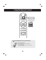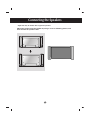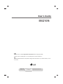
1
User’s Guide
M4210N
Make sure to read the Important Precautions before using the product.
Keep the User's Guide(CD) in an accessible place for furture reference.
See the label attached on the product and give the information to your dealer when you ask
for service.
Important
WARRANTY VOID
IF REMOVED
3850TAZ209Y
Warranty void if removed.
Safety Precautions
WARNING -This is a class A product. In a domestic environment this product may cause radio
interference in which case the user may be required to take adequate measures.
Please read these safety precautions carefully before using the product.
Warning If you ignore the warning message, you may be seriously injured or there is a possibility of
accident or death.
Caution If you ignore the caution message, you may be slightly injured or the product may be damaged
Precautions in installing the Product
Warning
Keep away from heat sources like electrical heaters.
- Electrical shock, fire, malfunction or deformation may occur.
Keep the packing anti-moisture material or vinyl packing out of the reach of children.
- Anti-moisture material is harmful if swallowed. If swallowed by mistake, force the patient to vomit and visit the
nearest hospital. Additionally, vinyl packing can cause suffocation. Keep it out of the reach of children.
Do not put heavy objects on the product or sit upon it.
- If the product collapses or is dropped, you may be injured. Children must pay particular attention.
Do not leave the power or signal cable unattended on the pathway.
- The passerby can falter, which can cause electrical shock, fire, product breakdown or injury.
Install the product in a neat and dry place.
- Dust or moisture can cause electrical shock, fire or product damage.
If you can smell smoke or other odors or hear a strange sound unplug the power cord and contact the
service center.
- If you continue to use without taking proper measures, electrical shock or fire can occur.
If you dropped the product or the case is broken, turn off the product and unplug the power cord.
- If you continue to use without taking proper measures, electrical shock or fire can occur. Contact the service
center.
Do not drop an object on or apply impact to the product. Do not throw any toys or objects on the product
screen.
- It can cause injury to human, problem to product and damage the display.
Caution
Make sure the product ventilation hole is not blocked. Install the product in a suitably wide place (more
than 10cm from the wall)
- If you install the product too close to the wall, it may be deformed or fire can break out due to internal heat.
Do not block the ventilation hole of the product by a tablecloth or curtain.
- The product can be deformed or fire can break out due to overheating inside the product.
Install the product on a flat and stable place that has no risk of dropping the product.
- If the product is dropped, you may be injured or the product may be broken.
Install the product where no EMI occurs.
Keep the product away from direct sunlight.
- The product can be damaged.
1
Safety Precautions
Electrical Power Related Precautions
Warning
Make sure to connect the power cable to the grounded current.
- You may be electrocuted or injured.
Use the rated voltage only.
- The product can be damaged, or you may be electrocuted.
In the presence of thunder and lightning, never touch the power cord and signal cable because it can be
very dangerous.
- It can cause electric shock.
Do not connect several extension cords, electrical appliances or electrical heaters to a single outlet.
Use a power bar with a grounding terminal designed for exclusive use with the computer.
- A fire can break out due to overheating.
Do not touch the power plug with wet hands. Additionally, if the cord pin is wet or covered with dust, dry
the power plug completely or wipe dust off.
- You may be electrocuted due to excess moisture.
If you don’t intend to use the product for a long time, unplug the power cable from the product.
- Covering dust can cause a fire, or insulation deterioration can cause electric leakage, electric shock or fire.
Fix the power cable completely.
- If the power cable is not fixed completely, a fire can break out.
Hold the plug when pulling out the power cable. Do not bend the power cord with excessive force or put
heavy objects on the power cord.
- The power line can be damaged, which may cause electric shock or fire.
Do not insert a conductor (like a metal chopstick) into one end of the power cable while the other end is
connected to the input terminal on the wall. Additionally, do not touch the power cable right after
plugging into the wall input terminal.
- You may be electrocuted.
The power supply cord is used as the main disconnection device. Ensure that the socket-outlet is easily
accessible after installation.
Main power breaker is the power cord and this breaking device must be located at a location where it is easy
to operate.
Caution
Do not unplug the power cord while the product is in use.
- Electrical shock can damage the product.
Precautions in Moving the Product
Warning
Make sure to turn off the product.
- You may be electrocuted or the product can be damaged.
Make sure to remove all cables before moving the product.
- You may be electrocuted or the product can be damaged.
2
Safety Precautions
Caution
Do not shock the product when moving it.
- You may be electrocuted or the product can be damaged.
Do not dispose the product-packing box. Use it when you move.
Make the panel face forward and hold it with both hands to move.
- If you drop the product, the damaged product can cause electric shock or fire. Contact with the service center
for repair.
Precautions in Using the Product
Warning
Do not disassemble, repair or modify the product at your own discretion.
- Fire or electric shock accident can occur.
- Contact the service center for check, calibration or repair.
When cleaning the brown tube surface, unplug the power cord and scrub with soft cloth to prevent
scratching. Do not clean with a wet cloth.
Keep the product away from water.
- Fire or electric shock accident can occur.
Caution
Do not put or store inflammable substances near the product.
- There is a danger of explosion or fire due to careless handling of the inflammable substances.
When cleaning the brown tube surface, unplug the power cord and scrub with soft cloth to prevent
scratching. Do not clean with a wet cloth.
- The water can sink into the product, which can cause electric shock or serious malfunction.
Take a rest from time to time to protect your vision.
Keep the product clean at all times.
Take a comfortable and natural position when working with a product to relax the muscles.
Take a regular break when working with a product for a long time.
Do not press strongly upon the panel with a hand or sharp object such as nail, pencil or pen, or make
a scratch on it.
Keep the proper distance from the product.
- Your vision may be impaired if you look at the product too closely.
Set the appropriate resolution and clock by referring to the User’s Guide.
- Your vision can be impaired.
Use authorized detergent only when cleaning the product. (Do not use benzene, thinner or alcohol.)
- Product can be deformed.
On Disposal
The fluorescent lamp used in this product contains a small amount of mercury.
Do not dispose of this product with general household waste.
Disposal of this product must be carried out in accordance to the regulations of your local authority.
3
Using the Remote Control
Name of the Remote Control Buttons (A type)
• Power On/Off Button
• Mute button
SLEEP
There is not a function
which is supported
Input Select Button
(See next page)
• CTR.PWR Button
Turn on the power of the PC built
in the monitor and then turn off.
(The CTR.PWR function
operates only when the PC
Control menu is off.)
• Menu Button
• Exit Button
• Volume
There is not a function
which is supported
Button
• Check Button
• UP and Down buttons
Bring up and down direction adjustment.
• Auto Button
Automatic adjustment function
(Operational for the analog signal only)
There is not a function
which is supported
• ARC button
To select the image
size of the screen.
• Video Operation Button
Applicable for LG products only
4
Using the Remote Control
SLEEP
• Input Select Button
If you press the button once,
the following Input Signal
Window will appear. Select
the signal type you want
using the
button.
INPUT
RGB
DVI
Inserting batteries into remote control.
1. Take out the battery cap.
2. Insert the batteries with correct polarity (+/-).
3. Close the battery cap.
• Dispose of used batteries in the recycle bin to prevent
environmental pollution.
5
Using the Remote Control
Name of the Remote Control Buttons (B type)
• Power On/Off Button
• Input Select Button
(See next page)
There is not a function
which is supported
• ARC button
To select the image size of the
screen.
• Auto Button
Automatic adjustment function
(Operational for the analog signal only)
There is not a function
which is supported
• CTR.PWR Button
Turn on the power of the PC built in the
monitor and then turn off.
(The CTR.PWR function operates only
when the PC Control menu is off.)
• Menu Button
1
2
3
4
5
6
7
8
9
CTR.
PWR
0
There is not a function
which is supported
There is not a function
which is supported
• Exit Button
• UP and Down buttons
Bring up and down direction
adjustment.
• Volume
Button
• Check Button
*
• Mute button
There is not a function
which is supported
6
Using the Remote Control
• Input Select Button
If you press the button once,
the following Input Signal
Window will appear. Select
the signal type you want
using the
button.
1
2
3
4
5
6
INPUT
RGB
DVI
7
8
CTR.
PWR
0
9
*
Inserting batteries into remote control.
1. Take out the battery cap.
2. Insert the batteries with correct polarity (+/-).
3. Close the battery cap.
• Dispose of used batteries in the recycle bin to prevent
environmental pollution.
7
Connecting the Speakers
* Applicable only for models that support the speakers
Mount the product onto the speaker by using a screw as following picture, and
then connect the speaker cable.
8
Name and Function of the Parts
* The product image in the user’s guide could be different from the actual image.
Rear View
REMOTE
CONTROL IN
RS-232C
(CONTROL&
SERVICE)
DVI IN
RGB IN
AUDIO
(RGB/DVI)
LAN
RGB OUT
H/PHONE
OUT
SP/DIF
USB
SERLAL
PORT
OUT
RGB OUT
IN
REMOTE
CONTROL IN
RS-232C
(CONTROL&
SERVICE)
DVI IN
RGB IN
AUDIO
(RGB/DVI)
LAN
RGB OUT
H/PHONE
OUT
SP/DIF
USB
SERLAL
PORT
OUT
RGB OUT
IN
Power Connector : Connect the power cord
Wired Remote Control Port
RS-232C Serial Ports
RGB, DVI Ports
PC Sound Jack
: Connect the audio cable to the *LINE OUT jack of the PC sound card.
LAN Ports
RGB out Ports
Head Phone out Port
Optical Sound out Ports
USB Ports
Serlal Ports
*LINE OUT
A terminal used to connect to the speaker including a built-in amplifier (Amp). Make sure that
the connecting terminal of the PC sound card is checked before connecting. If the Audio Out of
PC sound card has only Speaker Out, reduce the PC volume.
If the Audio Out of the PC sound card supports both Speaker Out and Line Out, convert to Line Out using
the card jumper of the program (Refer to the Sound Card Manual).
9
Connecting to External Devices
When Connecting to your Built in PC
When connecting with the DVI signal input cable.
1.
Rear side of the product.
REMOTE
CONTROL IN
RS-232C
(CONTROL&
SERVICE)
DVI IN
RGB IN
AUDIO
(RGB/DVI)
LAN
RGB OUT
H/PHONE
OUT
SP/DIF
USB
SERLAL
PORT
OUT
RGB OUT
IN
Connect the power cord.
2.
Turn on power by pressing the power button on the product.
SOURCE
3.
AUTO/SET
ON/OFF
Power button
Select an input signal.
Press the INPUT button on the remote control to select the input signal.
INPUT
SET
Or, press the SOURCE button at the back side of the product.
SOURCE
AUTO/SET
RGB
DVI
• Select DVI : DVI Digital signal.
4.
INPUT
Install the driver files contained at the supplied CD.
10
Connecting to External Devices
When connecting with the D-Sub signal input cable.
1.
2.
Install the Video driver file contained at the supplied CD.
Rear side of the product.
REMOTE
CONTROL IN
RS-232C
(CONTROL&
SERVICE)
DVI IN
RGB IN
AUDIO
(RGB/DVI)
LAN
RGB OUT
H/PHONE
OUT
SP/DIF
USB
SERLAL
PORT
OUT
RGB OUT
IN
RGB OUT
RGB IN
Connect the power cord.
3.
Turn on power by pressing the power button on the product.
SOURCE
AUTO/SET
ON/OFF
Power button
11
Connecting to External Devices
4.
1
Move the mouse pointer to an
empty area on the Windows
screen (with no icons or task
bars) and click the right
mouse button.
2
When the pop-up menu
appears, click the
'Properties' menu.
1
2
5.
1
Select 'Settings' tab.
2
Click 'Advanced' button.
12
Connecting to External Devices
6.
1
Select
'CATALYST(R)Control
Center' tab.
2
Click 'ATI
CATALYST(R)Control
Center' button.
7.
1
Select 'Display
Manager'menu.
2
13
Select 'Detect
Displays'button.
Connecting to External Devices
8.
1
2
1
Select gray monitor icon and then press the right button of the mouse.
2
Select 'Clone Main with monitor' menu.
9.
Click 'Yes' button.
10.
Select an input signal.
Press the INPUT button on the remote control to select the input signal.
INPUT
SET
Or, press the SOURCE button at the back side of the product.
SOURCE
RGB
AUTO/SET
DVI
• Select RGB : 15-pin D-Sub analog signal.
Note
INPUT
• How to connect to two computers.
Connect the signal cables (DVI and D-Sub) to each computer.
Press the INPUT button in a remote control to select the computer to use.
• Directly connect to a grounded power outlet on the wall or a power bar with a ground
wire.
14
Connecting to External Devices
When Connecting to your PC
1.
First of all, see if the computer, product and the peripherals are turned off.
Then, connect the signal input cable.
A When connecting with the D-Sub signal input cable.
B When connecting with the DVI signal input cable.
A
RGB IN
PC
Rear side of the product.
B
DVI IN
Rear side of the product.
PC
Connect the Audio cable.
AUDIO
(RGB/DVI)
PC
Rear side of the product.
Connect the power cord.
REMOTE
CONTROL IN
RS-232C
(CONTROL&
SERVICE)
DVI IN
RGB IN
AUDIO
(RGB/DVI)
LAN
RGB OUT
H/PHONE
OUT
SP/DIF
OUT
RGB OUT
IN
Rear side of the product.
15
USB
SERLAL
PORT
Connecting to External Devices
2.
1 Turn on power by pressing the power button on the product.
SOURCE
AUTO/SET
ON/OFF
Power button
2 Turn on the PC.
3.
Select an input signal.
Press the INPUT button on the remote control to select the input signal.
INPUT
SET
Or, press the SOURCE button at the back side of the product.
SOURCE
AUTO/SET
A
When connecting with a D-Sub signal input cable.
• Select RGB : 15-pin D-Sub analog signal.
B
When connecting with a DVI signal input cable.
• Select DVI : DVI Digital signal.
Note
INPUT
INPUT
RGB
RGB
DVI
DVI
• How to connect to two computers.
Connect the signal cables (DVI and D-Sub) to each computer.
Press the INPUT button in a remote control to select the computer to use.
• Directly connect to a grounded power outlet on the wall or a power bar with a ground
wire.
16
Connecting to External Devices
Watching RGB Outputs
Use this function when displaying ANALOG RGB inputs of a PC to the other product.
• To use different products connected to each other
Connect one end of the signal input cable(15-pin D-Sub Signal Cable) to the RGB OUT
connector of product 1 and connect the other end to the RGB IN connector of other
products.
15-pin D-Sub Signal Cable
RGB IN
RGB IN
RGB IN
RGB IN
RGB OUT
RGB OUT
RGB OUT
RGB OUT
PC
PC
Product 1
Note
Product 2
Product 3
Product 4
• When multi-connecting in/out cascade format, cables to be less damaged are recommended.
We recommend that you should use cable distributor.
17
To arrange cables using cable management
* Applicable only for models that support the stand.
1.
Arrange the cables in the center as shown in the following picture.
2.
Fit the cable management to the Holder Groove downwards.
cable
management
3.
Bundle the cables using the supplied twister holder.
twister holder
* When you want remove it.
Hold the Cable management with both
hands and pull it downward.
Warning
• Do not use the cable management as a handle for the Monitor.
• Do not press the cable management.
18
Attaching the product to a wall
* Applicable only for models that support the stand.
• Set it up close to the wall so the product doesn't fall over when it is pushed backwards.
The instructions shown below is a safer way to set up the product, which is to fix it on the wall so the product doesn't
fall over when it is pulled in the forward direction. It will prevent the product from falling forward and hurting people. It
will also prevent the product from damage caused by fall. Please make sure that children don't climb on or hang from
the product.
3
2
1
1. Use the braket and the bolt to fix the product to the wall as shown in the picture.
2. Secure the bracket with the bolt(not provided as parts of the product, must purchase separately) on the wall.
3. Use a sturdy rope (not provided as parts of the product, must purchase separately) to tie the product. It is
safer to tie the rope so it becomes horizontal between the wall and the product.
Note
• When moving the product to anoher place undo the ropes first.
• Use a product holder or a cabinet that is big and strong enough for the size and weight of the product.
• To use the product safely make sure that the height of the braket that is mounted on the wall is same as that of the
product.
19
Selecting and Adjusting the Screen
Name of the Buttons in the Screen Adjustment Unit
SOURCE
SOURCE
Power Button
AUTO/SET
AUTO/SET
ON/OFF
ON/OFF
• Press this button to turn on the power. Press this button again to
turn it off.
Power Indicator
• This Indicator lights up blue when the display operates normally(on
mode). If the display is in sleep (Energy Saving) mode, this indicator
color changes to amber.
MENU Button
• Use this button to show/hide the OSD (On Screen Display) menu
screen.
OSD Select /
Adjust Button
• Use this button to select an icon or adjust the setting in the OSD screen.
20
Selecting and Adjusting the Screen
Name of the Buttons in the Screen Adjustment Unit
AUTO/SET Button
If the resolution is 1360X768 (RGB Mode)
Auto in progress
If the resolution is not 1360X768 (RGB Mode)
Auto in progress
For optimal display
Change resolution to 1360 X 768
SOURCE Button
• Select the input signal
DVI (Digital signal)
RGB(Analog signal)
Digital signal and Analogue signal can't be outputted at the same time so
when transferring the source connect the connector and then turn on the
power.
IR Receiver
• The unit that receives the signal from the remote control.
21
Selecting and Adjusting the Screen
OSD Menu
Icon
Function Description
Adjusts screen brightness, contrast and color that you prefer.
PICTURE
Adjusts the audio function.
SOUND
Adjusts the screen status according to the circumstances.
SPECIAL
Adjusts the screen video.
SCREEN
Note
OSD(On Screen Display)
The OSD function enables you to adjust the screen status conveniently since it provides
graphical presentation.
22
Selecting and Adjusting the Screen
How to adjust the OSD (On Screen Display) screen
(A type)
Move where
you want to
adjust
Pops up
the menu
screen
Select a
menu icon
Move where
you want to
adjust
Select a
menu icon
Adjust the status
Save
adjustment
Exit from the
menu screen.
(B type)
• Use the remote control to adjust the OSD screen.
2
To access a control, use the
3
When the icon you want becomes highlighted, press the SET Button.
4
Use the
5
Accept the changes by pressing the SET Button.
6
Exit the OSD by pressing the EXIT Button.
Buttons.
Buttons to adjust the item to the desired level.
How to adjust the screen automatically
You need to adjust the screen display when
connecting the product to a new computer or changing
the mode. Refer to the following section to set an
optimal product screen.
If the resolution is 1360X768
Auto in progress
If the resolution is not 1360X768
Press the AUTO/SET button (AUTO button in a
remote Control) in the PC analog signal. Then, an
optimal screen status will be selected that fits into the
current mode.
If adjustment is not satisfactory, you need to adjust
screen position, clock and phase in the OSD menu.
23
Auto in progress
For optimal display
Change resolution to 1360 X 768
Selecting and Adjusting the Screen
Adjusting Screen Color
CSM
• 6500K/9300K
Selecting a factory setting color set.
6500K: Slightly reddish white.
9300K: Slightly bluish white.
CSM
• User : Select this option to use
the user-defined settings.
Contrast
To adjust the contrast of the screen.
Brightness
To adjust the brightness of the screen.
Red / Green / Blue
Set your own color levels.
CSM
24
Selecting and Adjusting the Screen
Adjusting the audio function
SSM
The best sound tone quality will be
selected automatically depending on the
video type that you're currently watching.
SOUND
SSM
Flat
Balance
Music
Movie
Sports
User
• Flat : The most commanding and natural audio.
• Music : Select this option to enjoy the original sound when listening to the music.
• Movie : Select this option to enjoy sublime sound.
• Sports: Select this option to watch sports broadcasting.
• User : Select this option to use the user-defined audio settings.
Balance
Use this function to balance sound from the left
SOUND
SSM
Balance
and right speakers.
0
L
Note
R
When connected to your computer and the 'SSM' setting in the audio menu is one of Flat, Music,
Movie or Sports, the available menus are Balance.
25
Selecting and Adjusting the Screen
Selecting the options
Reset
Input
If you press the button once, the following
Input Signal Window will appear. Select
the signal type you want using the
button.
Reset
Child lock
Use the
buttons to select On or Off. The Set can be set up so that it can only be used
with the remote control. This feature can prevent unauthorized viewing.
In order to lock the OSD screen adjustment, set the Child lock tab to the 'On' position.
In order to unlock it, do the following :
* Push the MENU button on the remote control and set Child lock to the 'Off' position.
Language
To choose the language in which the control names are displayed.
Power
indicator
Use this function to set the power indicator on the front side of the product to On or Off.
If you set Off, it will go off. If you set On at any time, the power indicator will
automatically be turned on.
Transparency
To adjust the transparency of the OSD menu screen.
26
Selecting and Adjusting the Screen
Selecting the options
• To use this function
- You can connect the product with several other products and use the Tile mode function.
Tile mode
Tile mode
Off
It is used to enlarge the screen and also used with
several products to view screen,
H-Size
0
V-Size
0
H-Position
V-Position
Reset
Reset
ID
• Tile mode
Tile mode and choose Tile alignment and set the ID of the current product to set location.
• H Size
Adjust the horizontal size of the screen taking into account the size of the bezel.
• V Size
Adjust the vertical size of the screen taking into account the size of the bezel.
• H-Position
Adjust the horizontal position of the screen taking into account the size of the bezel.
• V-Position
Adjust the vertical position of the screen taking into account the size of the bezel.
• Reset
Function to initialize and release Tile. All Tile setting are released when selecting.
Tile recall and the screen returns to Full screen.
• ID
Select the location of the Tile by setting an ID.
27
Selecting and Adjusting the Screen
Selecting the options
• Tile mode
- Tile mode : row x column ( r = 1, 2, 3, 4 c = 1, 2, 3, 4)
- 4 x 4 available.
- Configuration of an integration screen is also available as well as configuration of one by one Display.
- Tile mode (product 1 ~ 4) : r(2) x c(2)
row
ID 1
ID 2
column
ID 3
ID 4
- Tile mode (product 1 ~ 9) : r(3) x c(3)
row
ID 1
ID 2
ID 3
ID 4
ID 5
ID 6
ID 7
ID 8
ID 9
28
column
Selecting and Adjusting the Screen
Selecting the options
- Tile mode (product 1 ~ 2) : r(2) x c(1)
row
ID 2
ID 1
column
Reset
Use this function to reset the product to the factory default. However, language selection
and PC Control selection will not be initialized.
Set ID
Set ID
Logo light
You can assign a unique Set ID NO (name
assignment) to each product when several
products are connected for display. Specify
the number (1~99) using the
button
and exit. Use the assigned Set ID to
individually control each product using the
Product Control Program.
ID
1
PC Control
Logo Light
Use this function to set the Logo Display Lamp on the front side of the product to On
or Off. If you set On, the lamp will automatically be turned on.
PC Control
You can change the power setting of the PC built in the monitor.
On : Turn on/off both the monitor and the built-in PC.
Off : Turn on/off the built-in PC only.
* How to turn on or off the PC built in the monitor after setting it to Off?
(a) Press the power button at the rear side of the monitor and the SOURCE button at once.
(b) Or, press the CRT.PWR button (for the B type) or the SLEEP button (for the A type) at the
remote control.
29
Selecting and Adjusting the Screen
Adjusting Screen CLOCK/PHASE and Position
Auto-configure
ARC
To select the image size of the screen.
(1:1 menu are not supported over 1360 X 768 resolution)
Auto-configure
Auto-configure
This button is for the automatic adjustment of the screen position, clock and phase.
This function is suitable for analoge singnal input only.
Clock
To minimize any vertical bars or stripes visible on the screen background. The horizontal
screen size will also change. This function is suitable for analoge singnal input only.
Phase
To adjust the focus of the display. This item allows you to remove any horizontal noise
and clear or sharpen the image of characters. This function is suitable for analoge
singnal input only.
To adjust position of the screen.
This function is suitable for analoge singnal
input only.
Position
Auto-configure
H-Position
0
V-Position
0
30
Troubleshooting
No image is displayed
● Is the product power cord connected?
• See if the power cord is properly connected to the
outlet.
● Is the power indicator light on?
• See if the power switch is turned on.
● Power is on, power indicator is green • Adjust brightness and contrast again.
but the screen appears extremely dark.
● Is the power indicator amber?
• If the product is in power saving mode, move the
mouse or press any key.
● Does the 'Out of range' message
appear?
• The signal from the PC (video card) is out of the
vertical or horizontal frequency range of the
product. Adjust the frequency range by referring
to the Specifications in this manual.
* Maximum resolution
RGB : 1280 X 1024 @60Hz
DVI : 1280 X 1024 @60Hz – It may not be supported
depending on the OS or video card type.
● Does the 'Power saving mode DVI' • Connect the RGB cable, and then change the
message appear?
input source to 'RGB'.
And then, press the MENU button to set the PC
Control value of the SPECIAL menu to 'On'.
Disconnect RGB cable, and turn off the power,
and then turn power again.
● Does the 'Check signal cable' message • The signal cable between PC and product is not
connected. Check the signal cable.
appear?
• Press the 'INPUT' menu in the remote Control to
check the input signal.
● Did you check the INPUT Key?
Note
• Press the 'INPUT' menu in the remote Control to
check the input signal.
* Vertical frequency: To enable the user to watch the product display, screen image should be changed tens of times
every second like a fluorescent lamp. The vertical frequency or refresh rate is the times of image display per second.
The unit is Hz.
* Horizontal frequency: The horizontal interval is the time to display one vertical line. When 1 is divided by the
horizontal interval, the number of horizontal lines displayed every second can be tabulated as the horizontal
frequency. The unit is kHz.
31
Troubleshooting
The screen image looks abnormal.
● Is the screen position wrong at the
RGB mode?
• Press the “AUTO” button in the remote control to
automatically select the optimal screen status that
fits into the current mode. If adjustment is not
satisfactory, use the Position OSD menu.
• See if the video card resolution and frequency are
supported by the product. If the frequency is out of
range, set to the recommended resolution in the
Control Panel – Display – Setting menu.
● Do thin lines appear on the
background screen at the
RGB mode?
• Press the “AUTO” button in the remote control to
automatically select an optimal screen status that
fits into the current mode. If adjustment is not
satisfactory, use the Clock OSD menu.
● Horizontal noise appears or the
characters look blurred at the
RGB mode.
• Press the “AUTO” button in the remote control to
automatically select an optimal screen status that
fits into the current mode. If adjustment is not
satisfactory, use the Phase OSD menu.
● The screen is displayed abnormally at
the RGB mode.
• The proper input signal is not connected to the
signal port. Connect the signal cable that matches
with the source input signal.
The audio function does not work.
● No sound?
• See if the audio cable is connected properly.
• Adjust the volume.
• See if the sound is set properly.
• Select the appropriate equalize sound.
● Sound is too dull.
• Adjust the volume.
● Sound is too low.
32
Troubleshooting
'Child lock on' message appears.
● The 'Child lock on' message
appears when pressing the Menu
button.
Push the MENU button on the remote control and set
Child lock to the 'Off' position.
After-image appears on the product.
● After-image appears when the
product is turned off.
• If you use a fixed image for a long time, the pixels
may be damaged quickly. Use the screensaver
function.
Screen color is abnormal.
● Screen has poor color resolution
(16 colors).
• Set the number of colors to more than 32 bits (true
color)
Select Control Panel – Display – Settings – Color
Table menu in Windows.
● Do black spots appear on the screen?
• Several pixels (red, green, white or black color)
may appear on the screen, which can be
attributable to the unique characteristics of the
LCD panel. It is not a malfunction of the LCD.
33
Specifications
The product specifications can change without prior notice for product improvement.
LCD Panel
Power
Dimensions
&Weight
42 inches (106.73 cm) TFT (Thin Film Transistor)
LCD (Liquid Crystal Display) Panel
Anti-Glare coating
Visible diagonal size: 106.73 cm
0.681 mm (Pixel Pitch)
Rated Voltage
Power Consumption
AC 100-240V~ 50/60Hz 2.7A
On Mode
: 270W Typ.(with PC), 240W Typ.(only Monitor)
Sleep Mode
: ≤ 20W (only Monitor), 60W(with PC),
Off Mode
: ≤ 5W
[2]
[1]
H
H
W
D
W
D
[4]
[3]
H
H
W
D
W
D
Width x Height x Depth
[1] 99.56 cm (39.19 inches) x 67.41 cm (26.54 inches) x 29.30 cm (11.54 inches)
[2] 99.56 cm (39.19 inches) x 58.76 cm (23.13 inches) x 11.37 cm (4.47 inches)
[3] 112.76 cm (44.39 inches) x 67.41 cm (26.54 inches) x 29.30 cm (11.54 inches)
[4] 112.76 cm (44.39 inches) x 58.76 cm (23.13 inches) x 11.37 cm (4.47 inches)
Net
[1] 25.7 kg (56.65 lbs)
[3] 28.3 kg (62.38 lbs)
[2] 22.3 kg (49.16 lbs)
[4] 24.9 kg (54.89 lbs)
NOTE
Information in this document is subject to change without notice.
34
Specifications
The product specifications can change without prior notice for product improvement.
Video Signal
Max. Resolution
RGB : 1280 X 1024 @60Hz
DVI : 1280 X 1024 @60Hz – It may not be supported
depending on the OS or video card type.
Recommended Resolution RGB : WSXGA 1360 X 768 @60Hz
DVI : WSXGA 1360 X 768 @60Hz
Horizontal Frequency
RGB : 30 - 83 kHz
DVI : 30 - 72 kHz
Vertical Frequency
56 - 75 Hz (RGB / DVI)
Synchronization Type Separate/Composite/Digital
15-pin D-Sub type, DVI (digital), RS-232C
Input Connector
Environmental
Conditions
Operational Condition Temperature: 5˚C ~ 35˚C , Humidity: 10% ~ 80%
Storage Condition
Temperature: -20˚C ~ 60˚C , Humidity: 5% ~ 95%
* Applicable only for models that support the speakers
Audio
RMS Audio Output
Input Sensitivity
Speaker Impedance
10W+10W(R+L)
0.7Vrms
8Ω
NOTE
Information in this document is subject to change without notice.
35
Specifications
PC Mode – Preset Mode
Preset mode
1
2
3
4
5
6
7
8
9
VGA
VGA
VGA
VESA
VESA
VESA
MAC
VESA
VESA
640 x 350
720 x 400
640 x 480
640 x 480
800 x 600
800 x 600
832 x 624
1024 x 768
1024 x 768
Horizontal
Frequency
(kHz)
Vertical
Frequency
(Hz)
31.469
31.468
31.469
37.500
37.879
46.875
49.725
48.363
60.123
70
70
60
75
60
75
75
60
75
Preset mode
10
11
12
13
Power Indicator
Mode
On Mode
Sleep Mode
Off Mode
Product
Blue
Amber
-
36
VESA 1280 x 720
VESA 1280 x 768
VESA 1360 x 768
VESA 1280 x 1024
Horizontal Vertical
Frequency Frequency
(Hz)
(kHz)
44.772
47
47.72
63.981
60
60
60
60
Specifications
VESA wall mounting
Connected to another object (stand type and wall-mounted type.) This product accepts a VESAcompliant mounting interface pad.- (This has to be purchased separately if required.)
For further information, refer to the VESA Wall Mounting Instruction Guide.
Kensington Security Slot- (This has to be purchased
separately if required.)
Connected to a locking cable that can be purchased
separately at most computer stores
37
Specifications
Signal Connector Pin Assignment
8
16
24
1
9
17
DVI-D Connector
Pin
1
2
3
4
5
6
7
8
9
10
11
12
13
14
15
Signal(DVI-D)
Pin
16
17
18
19
20
21
22
23
24
T. M. D. S. Data2T. M. D. S. Data2+
T. M. D. S. Data2/4 Shield
T. M. D. S. Data4T. M. D. S. Data4+
DDC Clock
DDC Data
Analog Vertical Sync.
T. M. D. S. Data1T. M. D. S. Data1+
T. M. D. S. Data1/3 Shield
T. M. D. S. Data3T. M. D. S. Data3+
+5V Power
Ground (return for +5V,
Signal(DVI-D)
Hot Plug Detect
T. M. D. S. Data0T. M. D. S. Data0+
T. M. D. S. Data0/5 Shield
T. M. D. S. Data5T. M. D. S. Data5+
T. M. D. S. Clock Shield
T. M. D. S. Clock+
T. M. D. S. Clock-
H. Sync. and V. Sync.)
T. M. D. S. (Transition Minimized Differential Signaling)
38
Specifications
Connecting the USB(Universal Serial Bus) Cable
"USB (Universal Serial Bus)" is an innovation in connecting your different desktop peripherals conveniently to
your computer. By using the USB, you will be able to connect your mouse, keyboard, and other peripherals to
your display instead of having to connect them to your computer. This will give you greater flexibility in setting up
your system. USB allows you to connect a chain of up to 120 devices on a single USB port; and you can “hot”
plug (attach them while the computer is running) or unplug them while maintaining the Plug and the Plug auto
detection and configuration. This display has an integrated BUS-powered USB hub, allowing up to 2 other USB
devices to be attached it.
1.
2.
Connect the upstream port of the display to the downstream port of the USB compliant
PC or another hub using the USB cable.
Connect the USB compliant peripherals to the downstream ports of the display.
RGB OUT
H/PHONE
OUT
SP/DIF
USB
SERLAL
PORT
USB downstream Port
connect the cables from USB
compliant peripherals-such as
keyboard, mouse, etc
3. The monitor’s USB terminal supports USB 2.0 and High Speed cables.
Data Rate
Power
Consumption
High Speed
Full Speed
Low Speed
480Mbps
12Mbps
1.5Mbps
2.5W
(Max,each Port)
2.5W
2.5W
(Max,each Port)
(Max,each Port)
NOTE
To activate the USB hub function, the display must be connected to a USB compliant
PC(OS) or another hub with the USB cable(enclosed).
When connecting the USB cable, check that the shape of the connector at the cable side
matches the shape at the connecting side.
Even if the display is in a power saving mode, USB compliant devices will function when
they are connected the USB ports(both the upstream and downstream) of the display.
39
RS-232C
Controlling the Multiple Product
Use this method to connect several products to a single PC.
You can control several products at a time by connecting them to a single PC.
Connecting the cable
Connect the RS-232C cable as shown in the picture.
* The RS-232C protocol is used for communication between the PC and product. You can
turn the product on/off, select an input source or adjust the OSD menu from your PC.
Product 3
Product 2
Product 4
RS-232C
(CONTROL&
SERVICE)
RS-232C
(CONTROL&
SERVICE)
RS-232C
(CONTROL&
SERVICE)
OUT
OUT
OUT
IN
IN
IN
RS-232C Cable
RS-232C Cable
RS-232C
(CONTROL&
SERVICE)
OUT
IN
Product 1
Communication Parameter
▲▲ ▲ ▲ ▲▲
Baud Rate : 9600buadRate (UART)
Data Length : 8bits
Parity Bit : None
Stop Bit : 1bit
Flow Control : None
Communication Code : ASCII code
1
RS-232C
Controlling the Multiple Product
Command Reference List
01. Power
02. Main Input Select
03. Aspect Ratio
04. Screen Mute
05. Volume Mute
06. Volume Control
07. Contrast
08. Brightness
09. OSD Select
10. Remote On/Off
11. Balance
12. Select Color Temp
13. Auto Configure
14. Red Gain Adjust
15. Green Gain Adjust
16. Blue Gain Adjust
17. Tiling Mode
18. Tile H Position
19. Tile V Position
20. Tile H Size
21. Tile V Size
22. Tile ID Set
23. Temperature Check
24. Inverter Adjust
25. PC Power On/Off
26. PC Control On/Off
27. Input Select
COMMAND1
k
k
k
k
k
k
k
k
k
k
k
k
j
j
j
j
d
d
d
d
d
d
d
d
d
d
x
2
COMMAND2
a
b
c
d
e
f
g
h
l
m
t
u
u
w
y
z
d
e
f
g
h
i
n
r
s
t
b
DATA(Hexa)
00H - 01H
01H,07H, 09H
08H, 09H
00H - 01H
00H - 01H
00H - 64H
00H - 64H
00H - 64H
00H - 01H
00H - 01H
00H - 64H
00H - 02H
01H
00H - 64H
00H - 64H
00H - 64H
00H - 44H
00H - 64H
00H - 64H
00H - 64H
00H - 64H
00H - 10H
FFH
00H - 01H
00H - 01H
00H - 01H
01H,06H, 08H
RS-232C
Controlling the Multiple Product
Transmission / Receiving Protocol
Transmission
[Command1][Command2][ ][Set ID][ ][Data][Cr]
* [Command 1]: First command. (k)
* [Command 2]: Second command. (a ~ u)
* [Set ID]: You can adjust the set ID to choose desired product
ID number in Special menu. Adjustment range is 1 ~99.
When selecting Set ID ‘0’, every connected
set is controlled. Set ID is indicated as decimal
(1~255) on menu and as Hexa decimal (0x0~0x64)
on transmission/receiving protocol.
* [DATA]: To transmit command data.
Transmit 'FF' data to read status of command.
* [Cr]: Carriage Return
ASCII code ‘0x0D’
* [ ]: ASCII code Space (0x20)’
OK Acknowledgement
[Command2][ ][Set ID][ ][OK][Data][x]
* The Product transmits ACK (acknowledgement) based on
this format when receiving normal data. At this time, if the
data is data read mode, it indicates present status data.
If the data is data write mode, it returns the data of the PC
computer.
Error Acknowledgement
[Command2][ ][Set ID][ ][NG][Data][x]
* The Product transmits ACK (acknowledgement) based on
this format when receiving abnormal data from non-viable
functions or communication errors.
Data 1: Illegal Code
2: Not supported function
3: Wait more time
3
RS-232C
Controlling the Multiple Product
Transmission / Receiving Protocol
▲
01. Power On(Command : a)
To control Power On/Off of the Set.
Transmission
[k][a][ ][Set ID][ ][Data][Cr]
Data 0 : Power Off
1 : Power On
ff: Read Status
Acknowledgement
[a][ ][Set ID][ ][OK][Data][x]
▲
To show the status of Power On/Off.
Transmission
[k][a][ ][Set ID][ ][FF][Cr]
Data 0 : Power Off
1 : Power On
ff: Read Status
Acknowledgement
[a][ ][Set ID][ ][OK][Data][x]
* The Product transmits ACK (acknowledgement) based on
this format when receiving normal data. At this time, if the
data is data read mode, it indicates present status data. If
the data is data write mode, it returns the data of the PC
computer.
▲
02. Main input Select(Command : b) (Main Picture Input)
To select input source for the Set.
You can also select an input source using the INPUT
button on the remote control.
Transmission
[k][b][ ][Set ID][ ][Data][Cr]
Data 1 : RGB
7 : RGB
9 : DVI
Acknowledgement
[b][ ][Set ID][ ][OK][Data][x]
4
RS-232C
Controlling the Multiple Product
Transmission / Receiving Protocol
▲
03. Aspect Ratio(Command : c) (Main picure format)
To adjust the screen format.
You can also adjust the screen format using the ARC
(Aspect Ratio Control) button on remote control or in the
Screen menu.
Transmission
[k][c][ ][Set ID][ ][Data][Cr]
Data 8 : Full mode
9 : 1:1 (
Acknowledgement
[c][ ][Set ID][ ][OK][Data][x]
▲
04. Screen Mute(Command : d)
To select screen mute on/off.
Transmission
[k][d][ ][Set ID][ ][Data][Cr]
Data 0 : Screen mute off (Picture on)
1 : Screen mute on (Picture off)
Acknowledgement
[d][ ][Set ID][ ][OK][Data][x]
5
RS-232C
Controlling the Multiple Product
Transmission / Receiving Protocol
▲
05. Volume Mute(Command : e)
To control On/Off of the Volume Mute.
Transmission
[k][e][ ][Set ID][ ][Data][Cr]
Data 0 : Volume Mute On (Volume Off)
1 : Volume Mute Off (Volume On)
Acknowledgement
[e][ ][Set ID][ ][OK][Data][x]
Data 0 : Volume Mute On (Volume Off)
1 : Volume Mute Off (Volume On)
▲
06. Volume Control(Command : f)
To adjust Volume .
Transmission
[k][f][ ][Set ID][ ][Data][Cr]
Data
Min : 00H ~ Max : 64H
(Hexadecimal code)
Acknowledgement
[f][ ][Set ID][ ][OK][Data][x]
Data
Min : 00H ~ Max : 64H
• Refer to ‘Real data mapping’ page 7.
6
RS-232C
Controlling the Multiple Product
Transmission / Receiving Protocol
▲
07. Contrast(Command : g)
To adjust screen contrast.
You can also adjust the contrast in the Picture menu.
Transmission
[k][g][ ][Set ID][ ][Data][Cr]
Data
Min : 00H ~ Max : 64H
• Refer to ‘Real data mapping’ as shown below.
Acknowledgement
[g][ ][Set ID][ ][OK][Data][x]
* Real data mapping
0 : Step 0
:
A : Step 10
:
F : Step 15
10 : Step 16
:
64 : Step 100
▲
08. Brightness(Command : h)
To adjust screen brightness.
You can also adjust the brightness in the Picture menu.
Transmission
[k][h][ ][Set ID][ ][Data][Cr]
Data
Min : 00H ~ Max : 64H
• Refer to ‘Real data mapping’ as shown below.
Acknowledgement
[h][ ][Set ID][ ][OK][Data][x]
* Real data mapping
0 : Step
:
A : Step 10
:
F : Step 15
10 : Step 16
:
64 : Step 100
7
RS-232C
Controlling the Multiple Product
Transmission / Receiving Protocol
▲
09. OSD Select(Command : l)
To control OSD on/off to the set.
Transmission
[k][l][ ][Set ID][ ][Data][Cr]
Data 0 : OSD Off
1 : OSD On
Acknowledgement
[l][ ][Set ID][ ][OK][Data][x]
Data 0 : OSD Off
1 : OSD On
▲
10. Remote On/Off (Command : m)
Lock the buttons at the rear side of the monitor and the button at the remote control.
Transmission
[k][m][ ][Set ID][ ][Data][Cr]
Data 0 : Off
1 : On
Acknowledgement
[m][ ][Set ID][ ][OK][Data][x]
Data 0 : Off
1 : On
▲
11. Balance (Command : t)
To adjust the sound balance.
Transmission
[k][t][ ][Set ID][ ][Data][Cr]
Data
Min : 00H ~ Max : 64H
32H : Center
00H : Left
64H : Right
Acknowledgement
[t][ ][Set ID][ ][OK][Data][x]
32H : Center
00H : Left
64H : Right
8
RS-232C
Controlling the Multiple Product
Transmission / Receiving Protocol
▲
12. Select Color Temp (Command : u)
To adjust the screen color temperature.
Transmission
[k][u][ ][Set ID][ ][Data][Cr]
Data 0 : User
1 : 9300K
2 : 6500K
Acknowledgement
[u][ ][Set ID][ ][OK][Data][x]
Data 0 : User
1 : 9300K
2 : 6500K
▲
13. Auto Configure(Command: j u)
To adjust picture position and minimize image shaking
automatically. it works only in RGB(PC) mode.
Transmission
[j][u][ ][Set ID][ ][Data][Cr]
Data 1 : To set
Acknowledgement
[u][ ][Set ID][ ][OK][Data][x]
9
RS-232C
Controlling the Multiple Product
Transmission / Receiving Protocol
▲
14. Red Gain Adjust (Command: j w)
To adjust Red color level.
Transmission
[j][w][ ][Set ID][ ][Data][Cr]
Data
Min : 00H ~ Max : 64H
Acknowledgement
[w][ ][Set ID][ ][OK][Data][x]
* When it is executed with the 6500K or 9300K selected, it is automatically changed to the USER.
▲
15. Green Gain Adjust (Command: j y)
To adjust Green color level.
Transmission
[j][y][ ][Set ID][ ][Data][Cr]
Data
Min : 00H ~ Max : 64H
Acknowledgement
[y][ ][Set ID][ ][OK][Data][x]
* When it is executed with the 6500K or 9300K selected, it is automatically changed to the USER.
▲
16. Blue Gain Adjust (Command: j z)
To adjust Blue color level.
Transmission
[j][z][ ][Set ID][ ][Data][Cr]
Data
Min : 00H ~ Max : 64H
Acknowledgement
[z][ ][Set ID][ ][OK][Data][x]
* When it is executed with the 6500K or 9300K selected, it is automatically changed to the USER.
10
RS-232C
Controlling the Multiple Product
Transmission / Receiving Protocol
▲
17. Tiling Mode (Command :d d)
Change a Tiling Mode.
Transmission
[d][d][][Set ID][][Data][x]
Data
Description
00
Tiling mode is off.
12
1 x 2 mode(column x row)
13
1 x 3 mode
14
1 x 4 mode
...
...
44
4 x 4 mode
* The data can not be set to 0X or X0 except 00.
Acknowledgement
[d][][00][][OK/NG][Data][x]
▲
18. Tile H Position (Command : d e)
To set the horizontal position.
Transmission
[d][e][][Set ID][][Data][x]
Data
Min : 00H ~ Max : 64H
(Hexadecimal code)
Acknowledgement
[e][][Set ID][][OK/NG][Data][x]
11
RS-232C
Controlling the Multiple Product
Transmission / Receiving Protocol
▲
19. Tile V Position(Command : d f)
To set the Vertical position.
Transmission
[d][f][][Set ID][][Data][x]
* The data range is from 00 to 64(in Hex).
Acknowledgement
[f][][Set ID][][OK/NG][Data][x]
▲
20. Tile H Size(Command : d g)
To set the Horizontal size.
Transmission
[d][g][][Set ID][][Data][x]
* The data range is from 00 to 64(in Hex).
Acknowledgement
[g][][Set ID][][OK/NG][Data][x]
▲
21. Tile V Size(Command : d h)
To set the Vertical size.
Transmission
[d][h][][Set ID][][Data][x]
* The data range is from 00 to 64(in Hex).
Acknowledgement
[h][][Set ID][][OK/NG][Data][x]
12
RS-232C
Controlling the Multiple Product
Transmission / Receiving Protocol
▲
22. Tile ID Set (Command : d i)
To assign the Tile ID for Tiling function.
Transmission
[d][i][][Set ID][][Data][x]
* The data range is from 00 to 10 tile mode. (in Hex).
Acknowledgement
[i][][Set ID][][OK/NG][Data][x]
▲
23. Temperature check (Command : d n)
To read the inside temperature value.
Transmission
[d][n][][Set ID][][Data][x]
* The data is always FF(in Hex).
Acknowledgement
[n][][Set ID][][OK/NG][Data][x]
Data are 1 byte long in Hex ASCII format.
▲
24. Inverter Adjust (Command : d r)
To adjust the Inverter.
Transmission
[d][r][][Set ID][][Data][x]
Data 0 : Inverter Off
1 : Inverter On
Acknowledgement
[r][][Set ID][][OK/NG][Data][x]
13
RS-232C
Controlling the Multiple Product
Transmission / Receiving Protocol
▲
25. PC Power On/Off (Command : d s)
To turn On and Off the built in PC.
Transmission
[d][s][][Set ID][][Data][x]
Data 0 : PC Power Off
1 : PC Power On
Acknowledgement
[s][][Set ID][][OK/NG][Data][x]
*This operates only when ‘PC Control’ is ‘Off’.
▲
26. PC Control On/Off (Command : d t)
It sets the synchronized power on/off between the built-in PC of the monitor and the monitor.
Transmission
[d][t][][Set ID][][Data][x]
Data 0 : Off
1 : On
Acknowledgement
[t][][Set ID][][OK/NG][Data][x]
▲
27. Input Selection (Command : b) (Main Picture Input)
To select input source for the Set.
You can also select an input source using the INPUT
button on the remote control.
Transmission
[x][b][ ][Set ID][ ][Data][Cr]
Data 01 : RGB
06 : RGB
08 : DVI
Acknowledgement
[b][ ][Set ID][ ][OK][Data][x]
14
IR Codes
RS-232C
▲
How to connect
Connect your wired remote control to Remote Control port on the Product.
▲
Output waveform
Remote Control IR Code
single pulse, modulated with 37.917KHz signal at 455KHz
Tc
Carrier frequency
FCAR = 1/Tc = fosc/12
Duty ratio = T1/Tc = 1/3
T1
▲
Configuration of frame
• 1st frame
Lead
code
Low
custom code
High
custom code
Data code
Data code
C0 C1 C2 C3 C4 C5 C6 C7 C0 C1 C2 C3 C4 C5 C6 C7 D0 D1 D2 D3 D4 D5 D6 D7 D0 D1 D2 D3 D4 D5 D6 D7
• Repeat frame
Repeat code
Tf
▲
Lead code
9ms
4.5ms
0.55ms
▲
Repeat code
9ms
2.25ms
▲
Bit description
• Bit "0"
• Bit "1"
0.56ms
0.56ms
1.12ms
2.24ms
▲
Frame interval : Tf
• The waveform is transmitted as long as a key is depressed.
Tf
Tf
Tf=108ms@455KHz
15
IR Codes
RS-232C
Function
Note
▲
R/C Button
▼
R/C Button
▲
00
01
02
03
08
C4
C5
09
0B
43
5B
44
10
11
12
13
14
15
16
17
18
19
D5
C6
79
77
AF
VOL( )
R/C Button
▲
Code(Hexa)
VOL( )
R/C Button
POWER ON/OFF
R/C Button (Power On/Off)
POWER ON
Discrete IR Code(Only Power On)
POWER OFF
Discrete IR Code(Only Power On)
MUTE
R/C Button
INPUT
MENU
EXIT
SET
R/C Button
Number Key 0
R/C Button
Number Key 1
R/C Button
Number Key 2
R/C Button
Number Key 3
R/C Button
Number Key 4
R/C Button
Number Key 5
R/C Button
Number Key 6
R/C Button
Number Key 7
R/C Button
Number Key 8
R/C Button
Number Key 9
R/C Button
RGB
DVI
ARC
ARC (1:1)
AUTO CONFIC
Discrete IR Code(Input RGB PC Selection)
R/C Button
R/C Button
R/C Button
Discrete IR Code(Input DVI Selection)
R/C Button
Discrete IR Code(Only 1:1 mode)
Discrete IR Code
16