1
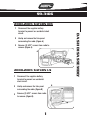
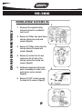
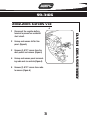
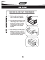
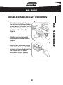
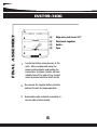
INSTALLATION INSTRUCTIONS FOR PART 99-3106
APPLICATIONS
SATURN
2003-05 Ion / 2000-05 LS
2000-02 SL / 2002-05 Vue
99-3106
KIT FEATURES
• Double DIN Head Unit Provisions with Pocket
• ISO DIN Head Unit Provisions with Pocket
KIT COMPONENTS
A) Radio Housing • B) Pocket • C) Radio Housing Brackets • D) (6) Phillips Screws
A
B
C
D
TOOLS REQUIRED:
Socket Wrench • Flat Blade Screwdriver • Phillips Screwdriver • Cutting Tool
1-800-221-0932
www.metraonline.com
Rev. 06-14-07 © COPYRIGHT 2004-2007 METRA ELECTRONICS CORPORATION INST99-3106
TABLE OF CONTENTS
99-3106
Dash Disassembly
2003-2005 Saturn Ion . . . . . . . . . . . . . . . . . . . . . . . . . . . . . . . 1
2000-2005 Saturn LS . . . . . . . . . . . . . . . . . . . . . . . . . . . . . . . 1
2000-2002 Saturn SL . . . . . . . . . . . . . . . . . . . . . . . . . . . . . . . 2
2002-2005 Saturn Vue . . . . . . . . . . . . . . . . . . . . . . . . . . . . . . . 3
Kit Assembly
ISO DIN head unit provisions . . . . . . . . . . . . . . . . . . . . . . . . . . 4
Double DIN head unit provisions . . . . . . . . . . . . . . . . . . . . . . . 5
Final Assembly . . . . . . . . . . . . . . . . . . . . . . . . . . . . . . . . . . . . 6
99-3106
2003-2005 SATURN ION
Disconnect the negative battery
terminal to prevent an accidental short
circuit.
2
Unclip and remove the trim panel
surrounding the radio. (Figure A)
3
Remove (2) 9/32” screws from radio to
remove. (Figure A)
DASH DISASSEMBLY
1
A
2000-2005 SATURN LS
1
Disconnect the negative battery
terminal to prevent an accidental
short circuit.
2
Unclip and remove the trim panel
surrounding the radio. (Figure B)
3
Remove (2) 9/32” screws from radio
to remove. (Figure B)
B
1
99-3106
2000-2002 SATURN SL
DASH DISASSEMBLY
A
1
Disconnect the negative battery
terminal to prevent an accidental
short circuit.
2
Remove (4) Phillips from panel below
steering column and unclip and
remove. (Figure A)
3
Remove (4) Phillips screws from the
steering column trim panel and
remove. (Figure B)
4
Remove (2) screws from the end
cap/vent on the left side of the
steering column then unclip and
remove. (Figure C)
5
Unclip and remove the entire dash
panel surrounding the radio, instrument cluster and a/c controls.
(Figure D)
6
Remove (2) 9/32” screws securing
the head unit to remove. (Figure D)
B
C
D
2
99-3106
2002-2005 SATURN VUE
A
Disconnect the negative battery
terminal to prevent an accidental
short circuit.
2
Unsnap and remove shifter trim
panel. (Figure A)
3
Remove (4) 9/32” screws from the
dash pocket and remove. (Figure A)
4
Unsnap and remove panel surrounding radio and a/c controls.(Figure A)
5
Remove (2) 9/32” screws from radio
to remove. (Figure A)
DASH DISASSEMBLY
1
3
99-3106
ISO DIN HEAD UNIT PROVISIONS
KIT ASSEMBLY
A
1
Slide the radio housing brackets
onto the radio housing. (Figure A)
2
Snap the pocket onto the back of the
radio housing, align the holes in the
pocket with the holes in the radio
housing brackets and mount with
the (6) Phillips screws supplied.
(Figure B)
3
B
Align the holes in the radio housing
brackets with the holes in the ISODIN head unit and secure the brackets to the head unit with the screws
included with the unit. (Figure C)
C
4
99-3106
DOUBLE DIN HEAD UNIT PROVISION
A
Cut and remove the center bar on
the radio housing (A), the protruding
bracket tabs (B), the bracket sockets
(C), and the locating pins on the
back of the radio housing (D).
(Figure A)
2
Slide the radio housing brackets
onto the sides of the radio housing.
(Figure A)
3
B
Align the holes in the radio housing
brackets with the holes in the DDIN
head unit and secure the brackets to
the head unit with the screws
included with the unit. (Figure B)
5
KIT ASSEMBLY
1
INST99-3106
FINAL ASSEMBLY
A
B
C
A)
Strip wire ends back 1/2"
B)
Twist ends together
C)
Solder
D)
Tape
D
1
Locate the factory wiring harness in the
dash. Metra recommends using the
proper mating adapter and making the
connections as shown. (Isolate and individually tape off the ends of any unused
wires to prevent electrical short circuit)
2
Re-connect the negative battery terminal
and test the unit for proper operation.
3
Reassemble radio and dash assemblies in
reverse order of disassembly.
6